04/000 Control Relays, Contactor Relays, Electronic Timing ...
63
Moeller HPL0211-2001/2002 Control Relays, Contactor Relays, Electronic Timing Relays, Electronic Safety Relays, Measuring and Monitoring Relays Relays Contactor Relays 04/000
Transcript of 04/000 Control Relays, Contactor Relays, Electronic Timing ...
Moeller HPL0211-2001/2002
Control Relays, Contactor Relays, Electronic Timing Relays, Electronic Safety Relays, Measuring and Monitoring Relays
Rela
ysCo
ntac
tor R
elay
s04/000
04/001Moeller HPL0211-2001/2002
Control Relays, Contactor Relays, Electronic Timing Relays, Electronic Safety Relays, Measuring and Monitoring RelaysOverview
Rela
ysCo
ntac
tor
Rela
ys
Control relays
AC and DC operated
PageSystem overview 04/002
‘Easy’ control relays 04/006Basic units 04/006
Accessories 04/008Expansion units 04/007
Technical data 04/037
Dimensions 04/064
Electronic timing relays
AC and DC operated
PageDILET
DILET11 on-delayed timing relay
04/016
DILET70 multi-function relay 04/016
ETR4ETR4-51 star-delta timing relay
04/018
ETR4-69 multi-function relay 04/018
ETR4-70 multi-function relay 04/020
Accessories 04/027
Tripping characteristics 04/033
Technical data 04/053
Dimensions 04/066
Contactor relays
AC and DC operated
PageSystem overview 04/004
DILER mini contactor relays 04/010Basic units 04/010Auxiliary contact modules 04/010
DILR contactor relays 04/012Basic units 04/012Auxiliary contact modules 04/012Complete units 04/014
Accessories 04/027
Contact travel diagrams 04/029
Actuating voltages 04/030
Tripping characteristics 04/032
Technical data 04/046
Dimensions 04/065
Electronic safety relays
PageEngineering 04/022
ESR safety relays 04/023For Emergency-Stop monitoring
04/023
For protective door monitoring 04/023For contact/safety mat monitoring 04/023For monitoring of two-hand controls
04/023
Contact expansion modules 04/023
Technical data 04/054
Dimensions 04/067
Measuring and monitoring relays
PageEMR4-I current monitoring relays 04/024
EMR4-F phase sequence relays 04/024
EMR4-W phase monitoring relays 04/024
EMR4-A phase imbalance monitoring relays
04/024
EMR4-N level monitoring relays 04/025
EMR4-R insulation monitoring relays
04/025
EMR4-PH sealable shroud 04/025
Tripping characteristics 04/034
Technical data 04/058
Dimensions 04/067

Moeller HPL0211-2001/2002
“Easy” Control RelaysSystem Overview
Rela
ysCo
ntac
tor R
elay
s04/002
25839436617571
Rela
ysCo
ntac
tor
Rela
ys
Moeller HPL0211-2001/2002
“Easy” Control RelaysSystem Overview
04/003
Distinguishing features of the EASY control relay• Wide operational temperature range
–25 °C to +55 °C• Standard front dimension for fitting into service
distribution boards, 18 mm standard slot• Electronic “wiring” by keystroke,
LCD (4 lines of 12 characters) and keypad or via software from the PC
• Zero-voltage safe internal and external circuit configuration storage in EEPROM memory
• 3 contacts (make or break contacts) in series plus one coil in each current path
• Series and parallel connection• 41 current paths / lines of logic EASY412• 121 current paths / lines of logic EASY600• Integral password protection for circuit
configuration and relay value presets • Current flow display for circuit configuration
testing (LCD Types)• Selection option from ten different menu
languages (EASY600) and five different menu languages (EASY412) D, GB, F, I, E, (P, NL, S, PL, TR)
Functions• 8 timing relays 0.01 s to 99 h 59 min
– On-delay– On-delay with random switching– Off-delay– Off-delay with random switching– Pulse shaping– Flashing
• 8 up- and down-counter relays, 0000 to 9999
• 4 weekly timers (4 channels per timer, one On/Off point per channel, optional on Types with clock)
• 8 analog value comparators, range 0 – 10 V (EASY...-D...-... Types only)
• 8 lines of text, can be freely edited (EASY600 with display)
• 16 auxiliary relays (EASY412), up to 32 auxiliary relays (EASY600)
• Retentive actual values EASY412-D... – 4 markers– 1 timing relay– 1 counter
• Retentive actual values EASY600– 12 markers– 2 timing relays– 4 counters, e.g. as hours-run meters
Basic units 1AC or DC operatedPower supplyAC 100 (115) – 240 V, 50/60 HzDC 24 V DCDA 12 V DC8 or 12 digital inputs(2 inputs usable as analog inputs [DC/DA variants only])4 or 6 relay outputs (max. 10 A)4 or 8 transistor outputsLCD display, X variants without LCDScrew fixing and snap fittingScrew terminals
a Page 04/006
Fixing brackets 2For optional screw fixing,3 brackets per relay for EASY4...minimum of 3 brackets per relay for EASY6...
a Page 04/008
External memory card 3For safe storage of the circuit configuration and all parameters
a Page 04/008
Connection cable 4Safe isolation between “easy” and PC
a Page 04/008
Basic units, expandable EASY619/621
5
AC or DC operatedPower supplyAC 100 – 240 V, 50/60 HzDC 24 V DC12 digital inputs(2 inputs usable as analog inputs [DC variants only]) 6 relay outputs (max. 10 A)8 transistor outputsLCD display, X variants without LCDScrew fixing and snap fittingScrew terminals
a Page 04/008
EASY-LINK-DS data plug 6For connecting the basic unit with the expansion unit
a Page 04/006
Expansion unit 7I/O expansionAC or DC operatedPower supply:AC 100 – 240 V, 50/60 HzDC 24 V DC12 digital inputs6 relay outputs (max. 10 A)8 transistor outputsScrew fixing and snap fittingScrew terminals
a Page 04/006
Networking / Bus interfacesEASY204-DPPROFIBUS-DP slave connectionEASY205-ASIAS-Interface slave connection
a Page 04/008
Coupling unit 8
a Page 04/007
Connection cable 9e.g. NYM 3 x 1.5 mm2
a Page 04/008
Moeller HPL0211-2001/2002
Contactor Relays, Electronic Timing RelaysSystem Overview
Rela
ysCo
ntac
tor R
elay
s04/004
DILER
DILR
Rela
ysCo
ntac
tor
Rela
ys
Moeller HPL0211-2001/2002
Contactor Relays, Electronic Timing RelaysSystem Overview
04/005
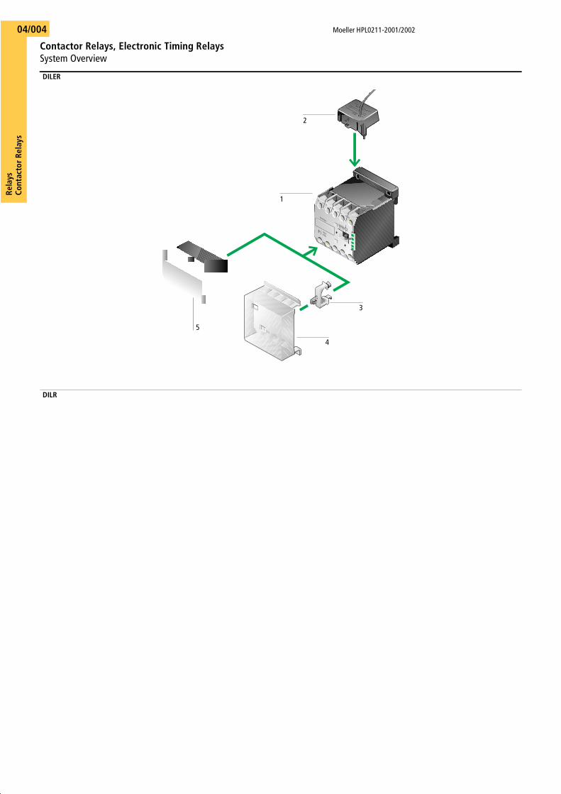
DILER mini contactor relays
Basic units 1AC or DC operatedMagnet systemsAC 12 – 480 V, 50, 60, 50/60 Hz
0.8 – 1.1 � Uc25 VA/4.6 VA
DC 12 – 220 V DC0.85 – 1.1 � Uc2.6 W/2.6 W
Maximum of eight contactsInterlocked opposing contactsModular systemScrew fixing and snap fittingFinger proofScrew terminals
a Page 04/010
DILR contactor relays
Basic units 1AC or DC operatedMagnet systemsAC 12 – 600 V, 50, 60, 50/60 Hz
0.8 – 1.1 � Uc60 VA/8.5 VA
DC 12 – 250 V DC0.85 – 1.1 � Uc9.5 W/9.5 W
Coils for non-standard voltagesMaximum of eight contactsInterlocked opposing contactsModular system/complete unitsScrew fixing and snap fittingFinger proofScrew terminals
a Page 04/010
Suppressors 2All contactor relays with DC operated coils have an integral suppressor circuitSuppressors for contactor relays with AC operated coils
a Page 04/026
Sealable shroud with clip 3, 4As cover in IVS enclosures
a Page 04/027
Auxiliary contact modules 52- or 4-poleOverlapping contactsInterlocked opposing contacts
a Page 04/010
Suppressors 2RC suppressorVaristor suppressorFree-wheel diode suppressor
a Page 04/026
Amplifier modules 3With and without integral suppressor circuitsPlug-in typeSeparate mounting
a Page 04/026
Auxiliary contact modules 42-polePlug-in typeInterlocked opposing contacts
a Page 04/012
Auxiliary contact modules 54-polePlug-in typeInterlocked opposing contacts
a Page 04/012
Pneumatic timer modules 6On- and Off-delayedWith or without TÜV* approval to VDE 0116*TÜV = German Technical Supervisory Association
a Page 04/012
Mechanical latching module 7Latches the contactor relay in the event of loss of control voltage
a Page 04/012
Moeller HPL0211-2001/2002
“Easy” Control RelaysBasic Units
Rela
ysCo
ntac
tor R
elay
s04/006
Description Type PriceArticle no. See Price List Std. pack
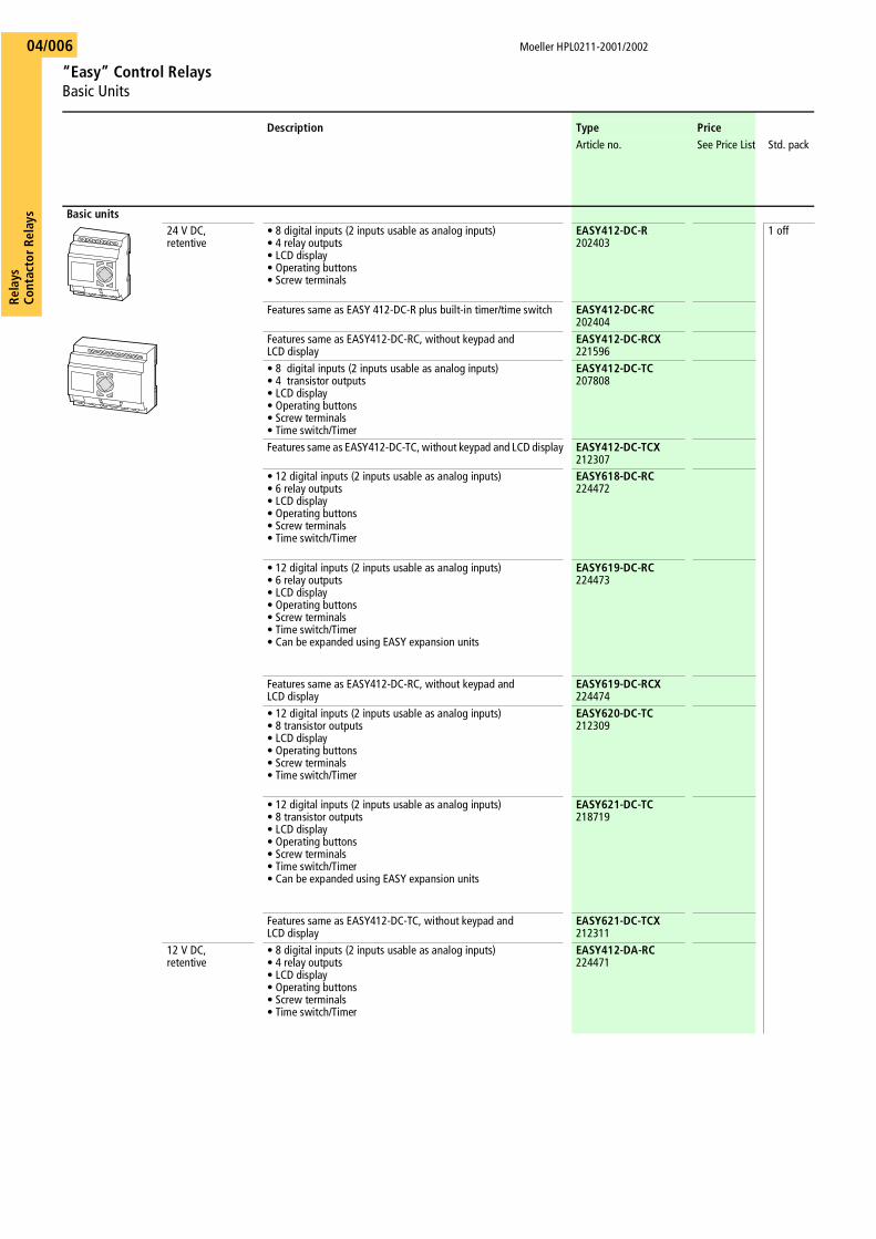
Basic units24 V DC, retentive
• 8 digital inputs (2 inputs usable as analog inputs)• 4 relay outputs• LCD display• Operating buttons• Screw terminals
EASY412-DC-R202403
1 off
Features same as EASY 412-DC-R plus built-in timer/time switch EASY412-DC-RC202404
Features same as EASY412-DC-RC, without keypad and LCD display
EASY412-DC-RCX221596
• 8 digital inputs (2 inputs usable as analog inputs)• 4 transistor outputs• LCD display• Operating buttons• Screw terminals• Time switch/Timer
EASY412-DC-TC207808
Features same as EASY412-DC-TC, without keypad and LCD display EASY412-DC-TCX212307
• 12 digital inputs (2 inputs usable as analog inputs)• 6 relay outputs• LCD display• Operating buttons• Screw terminals• Time switch/Timer
EASY618-DC-RC224472
• 12 digital inputs (2 inputs usable as analog inputs)• 6 relay outputs• LCD display• Operating buttons• Screw terminals• Time switch/Timer• Can be expanded using EASY expansion units
EASY619-DC-RC224473
Features same as EASY412-DC-RC, without keypad and LCD display
EASY619-DC-RCX224474
• 12 digital inputs (2 inputs usable as analog inputs)• 8 transistor outputs• LCD display• Operating buttons• Screw terminals• Time switch/Timer
EASY620-DC-TC212309
• 12 digital inputs (2 inputs usable as analog inputs)• 8 transistor outputs• LCD display• Operating buttons• Screw terminals• Time switch/Timer• Can be expanded using EASY expansion units
EASY621-DC-TC218719
Features same as EASY412-DC-TC, without keypad and LCD display
EASY621-DC-TCX212311
12 V DC, retentive
• 8 digital inputs (2 inputs usable as analog inputs)• 4 relay outputs• LCD display• Operating buttons• Screw terminals• Time switch/Timer
EASY412-DA-RC224471
ESCOK
DELALT
Rela
ysCo
ntac
tor
Rela
ys
Moeller HPL0211-2001/2002
“Easy” Control RelaysBasic Units, Expansion Units, Accessories
04/007
Description Type PriceArticle no. See Price List Std. pack
Basic units115/230 V AC • 8 digital inputs, 115/230 V AC
• 4 relay outputs• LCD display• Operating buttons• Screw terminals
EASY412-AC-R202405
1 off
Features same as EASY 412-AC-R, plus timer EASY412-AC-RC202406
Features same as EASY412-AC-RC, without keypad and LCD display EASY412-AC-RCX212308
115/230 V AC, retentive
• 12 digital inputs, 115/230 V AC• 6 relay outputs • LCD display• Operating buttons• Screw terminals• Time switch/Timer
EASY618-AC-RC212310
• 12 digital inputs, 115/230 V AC• 6 relay outputs• LCD display• Operating buttons• Screw terminals• Time switch/Timer• Can be expanded using EASY expansion units
EASY619-AC-RC218721
Features same as EASY619-AC-RC, without keypad and LCD display EASY619-AC-RCX212312
Expansion units24 V DC • 12 digital inputs
• 8 transistor outputs • With connector
EASY620-DC-TE212313
1 off
115/230 V AC • 12 digital inputs, 115/230 V AC• 6 relay outputs • With connector
EASY618-AC-RE212314
Coupling unit • Coupling unit for connecting to an EASY619/621 basic unit• Terminals for remote expansion, up to 30 m to/from the expansion
unit• With connector
EASY200-EASY212315
Expansion units for networkingAS-Interface • Linked directly to EASY619/621
• AS-Interface connection• Slave• 4 inputs, 4 outputs, 4 parameter bits• Addresses available: 0 to 31• With connector
EASY205-ASI221598
1 off
PROFIBUS DP • Linked directly to EASY619/621• PROFIBUS-DP slave• Addresses available: 0 to 126• With connector
EASY204-DP212316
1 off
Accessories for DPPROFIBUS DP bus connector plug
9-pole (pins), comes as a kit without cable, for connection of the data cable
ZB4-209-DS2206982
1 off
PROFIBUS DP bus connector plug
• Metallised insulated housing• Maximum transfer rate 12 MBit/s• Built-in switch (accessible from the outside) for the bus termination
resistances• Terminal block for two cables, optionally with straight
or 90° angled cable entry• Suitable for EASY204-DP
ZB4-209-DS3217820
PROFIBUS DPdata cable
Twisted pair cable, 2 X 0.64 mm2, length: 100 m ZB4-900-KB1206983
Moeller HPL0211-2001/2002
“Easy” Control RelaysNetworking, Accessories
Rela
ysCo
ntac
tor R
elay
s04/008
Description Type PriceArticle no. See Price List Std. pack
AccessoriesSoftware CD, menu selection from 6 languages
Installation under WIN 95, 98, WIN NT 4.0 Service Pack 3 and aboveEASY-SOFT202407
1 off
Memory card 8K memory card for storing the entire circuit configuration for EASY412 EASY-M-8K202408
16K memory card for storing the entire circuit configuration for EASY6.. EASY-M-16K212317
Connection cable Length: 2 m, for connection to 9-pole serial PC interface with interface electronics
EASY-PC-CAB202409
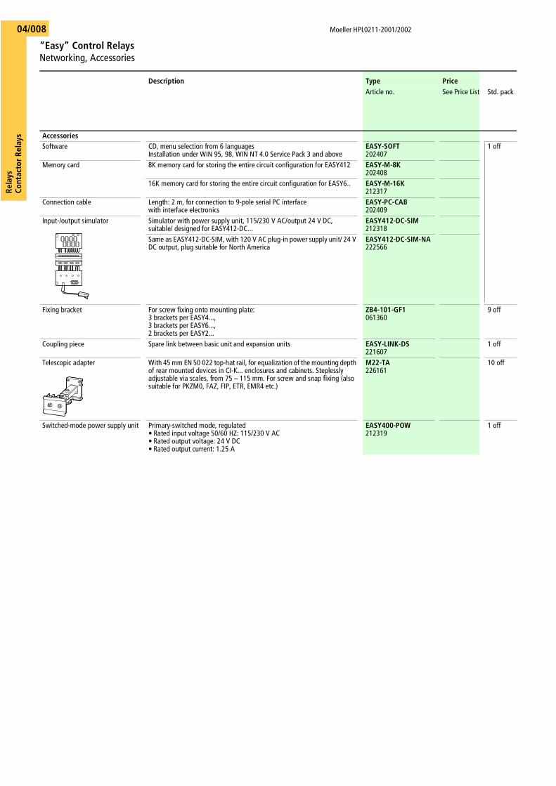
Input-/output simulator Simulator with power supply unit, 115/230 V AC/output 24 V DC, suitable/ designed for EASY412-DC...
EASY412-DC-SIM212318
Same as EASY412-DC-SIM, with 120 V AC plug-in power supply unit/ 24 V DC output, plug suitable for North America
EASY412-DC-SIM-NA222566
Fixing bracket For screw fixing onto mounting plate:3 brackets per EASY4...,3 brackets per EASY6...,2 brackets per EASY2...
ZB4-101-GF1061360
9 off
Coupling piece Spare link between basic unit and expansion units EASY-LINK-DS221607
1 off
Telescopic adapter With 45 mm EN 50 022 top-hat rail, for equalization of the mounting depth of rear mounted devices in CI-K... enclosures and cabinets. Steplessly adjustable via scales, from 75 – 115 mm. For screw and snap fixing (also suitable for PKZM0, FAZ, FIP, ETR, EMR4 etc.)
M22-TA226161
10 off
Switched-mode power supply unit Primary-switched mode, regulated• Rated input voltage 50/60 HZ: 115/230 V AC• Rated output voltage: 24 V DC• Rated output current: 1.25 A
EASY400-POW212319
1 off
Rela
ysCo
ntac
tor
Rela
ys
Moeller HPL0211-2001/2002
“Easy” Control RelaysDocumentation
04/009
Description Type PriceArticle no. See Price List Std. pack
DocumentationManual for the “Easy” control relay
German AWB2528-1304-D205375
1 off
English AWB2528-1304-GB205481
French AWB2528-1304-F205482
Italian AWB2528-1304-I205483
Spanish AWB2528-1304-E205484
Brief introduction to the “Easy” control relayGerman AWB2528-1316-D
2053761 off
English AWB2528-1316-GB205485
French AWB2528-1316-F205486
Italian AWB2528-1316-I205487
Spanish AWB2528-1316-E205488

Moe
ller H
PL02
11-2
001/
2002
DIL
ER M
ini C
onta
ctor
Rel
ays
Basi
c U
nits
, Mod
ules
RelaysContactor Relays
RelaysContactor Relays
Moe
ller H
PL02
11-2
001/
2002
DIL
ER M
ini C
onta
ctor
Rel
ays
Basi
c U
nits
, Mod
ules
AC
oper
atio
nD
C op
erat
ion
Cont
acts
Rate
d ope
ratio
nal
curre
nt I e
AC-1
5
Conv
. th
erm
.cu
rren
tI t
h
Type
Pric
eTy
pePr
ice
Not
esAr
ticle
no.
See
Pric
e Li
stSt
d. p
ack
Artic
le n
o.Se
e Pr
ice
List
Std.
pac
k
220
V23
0 V
240
V
380
V40
0 V
415
VM
= M
ake
B =
Bre
akA
AA
Circ
uit s
ymbo
lDi
stin
ctiv
e nu
mbe
r and
ve
rsio
n of
com
bina
tion
Circ
uit s
ymbo
lDi
stin
ctiv
e nu
mbe
r and
ve
rsio
n of
com
bina
tion
Basi
c un
its
wit
h in
terl
ocke
d op
posi
ng c
onta
cts
4 M
–6
310
40E
––
DIL
ER-4
0(23
0V50
HZ)
0517
595
off
40E
DIL
ER-4
0-G
(24V
DC)
0102
235
off
Oth
er a
ctua
ting
volta
ges
a
Pag
e 0
4/03
0 Co
ntac
t num
bers
to E
N50
011
Coil
term
inal
mar
king
s to
EN
5000
5W
ith D
C op
erat
ion:
in
tegr
al re
sist
or/d
iode
com
bina
tion
Coil
ratin
g: 2
.6 W
Acc
esso
ries
Page
1Su
ppre
ssor
04/0
26O
ther
acc
esso
ries
04/0
26
3 M
1 B
–31
E–
DIL
ER-3
1(23
0V50
HZ)
0517
6831
ED
ILER
-31-
G(2
4VD
C)01
0157
2 M
2 B
––
22E
DIL
ER-2
2(23
0V50
HZ)
0517
7722
ED
ILER
-22-
G(2
4VD
C)01
0042
Aux
iliar
y co
ntac
t m
odul
es w
ith
inte
rloc
ked
oppo
sing
con
tact
s1)
2-po
le
–2
B4
210
42E
3324
02D
ILE
0102
405
off
42E
33–
02D
ILE
0102
405
off
Vers
ion
E co
mbi
natio
ns
corr
espo
nd to
EN
5001
1 an
d ar
e to
be
pref
erre
d;
othe
r com
bina
tions
corre
spon
d to
EN
5000
5.1
M1
B51
E42
3311
DIL
E01
0224
51E
42–
11D
ILE
0102
24
2 M
–60
E51
4220
DIL
E01
0208
60E
51–
20D
ILE
0102
08
1 M
2)
1 B
2)51
4233
11D
DIL
E04
9824
5142
–11
DD
ILE
0498
24
4-po
le–
4 B
42
1044
E35
2604
DIL
E01
0256
5 of
f44
E35
–04
DIL
E01
0256
5 of
f
1 M
3 B
53E
4435
13D
ILE
0023
9753
E44
–13
DIL
E00
2397
2 M
2 B
62E
5344
22D
ILE
0102
8862
E53
–22
DIL
E01
0288
3 M
1 B
71E
6253
31D
ILE
0489
1271
E62
–31
DIL
E04
8912
4 M
–80
E71
6240
DIL
E01
0304
80E
71–
40D
ILE
0103
04
2 M
2)
2 B
2)62
5344
22D
DIL
E04
9823
6253
–22
DD
ILE
0498
23
Not
es1)
N
ot w
ith e
arly
-mak
e co
ntac
ts o
r lat
e-br
eak
cont
acts
2)
1 ea
rly-m
ake
cont
act
1 la
te-b
reak
con
tact
141333 34
43 44
A1 A2
23 241413
33 34
43 44
A1 A2
23 24
1
14
1321
22
33
34
43
44
A1
A2
14
13
A1
A2
21
22
33
34
43
44
14
1321
2231
32
43
44
A1
A2
14
13
A1
A2
21
22
31
32
43
44
Moe
ller H
PL02
11-2
001/
2002
DIL
R Co
ntac
tor
Rela
ysBa
sic
Uni
ts, M
odul
es
RelaysContactor Relays
RelaysContactor Relays
Moe
ller H
PL02
11-2
001/
2002
DIL
R Co
ntac
tor
Rela
ysBa
sic
Uni
ts, M
odul
es
AC
oper
atio
n D
C op
erat
ion
Cont
acts
Rate
d op
erat
iona
l cu
rren
t Ie
AC-1
5
Conv
. th
erm
. cu
rrent
I th
Type
Pric
eTy
pePr
ice
Artic
le n
o.Se
e Pr
ice
List
Std.
pac
kAr
ticle
no.
See
Pric
e Li
stSt
d. p
ack
Not
es
220
V23
0 V
240
V
380
V40
0 V
415
VM
= M
ake
B =
Bre
ak
AA
ACi
rcui
t sym
bol
Dist
inct
ive
num
ber a
nd
vers
ion
of c
ombi
natio
n
Basi
c un
its
wit
h in
terl
ocke
d op
posi
ng c
onta
cts
4 M
–6
416
40 E
––
DIL
R40(
230V
50H
Z)04
3756
1 of
fD
ILR4
0-G
(24V
DC)
0485
371
off
Oth
er a
ctua
ting
volta
ges
a P
age
04/0
30
Cont
act n
umbe
rs to
EN
5001
1Co
il te
rmin
al m
arki
ngs
to E
N50
005
DILR
40: s
uppl
ied
with
out f
ront
pla
teFr
ont p
late
a P
age
05/0
47
Acc
esso
ries
Page
1Am
plifi
er m
odul
e04
/026
Oth
er a
cces
sorie
s04
/026
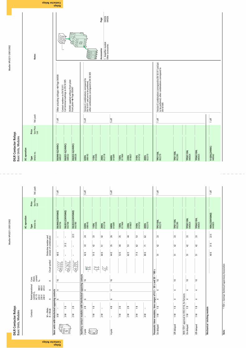
3 M
1 B
–31
E–
DIL
R31(
230V
50H
Z)04
3768
DIL
R31-
G(2
4VD
C)04
8532
2 M
2 B
––
22 E
DIL
R22(
230V
50H
Z)04
3780
DIL
R22-
G(2
4VD
C)04
8526
Aux
iliar
y co
ntac
t m
odul
es w
ith
inte
rloc
ked
oppo
sing
con
tact
s2-
pole
–2
B6
416
42 E
33
2402
DIL
0981
455
off
02D
IL09
8145
5 of
fVe
rsio
n E
com
bina
tions
cor
resp
ond
to
EN50
011
and
are
to b
e pr
efer
red;
ot
her c
ombi
natio
ns c
orre
spon
d to
EN
5000
5
1 M
1 B
51 E
42
33
11D
IL01
0345
11D
IL01
0345
2 M
–60
E51
42
20
DIL
0127
1820
DIL
0127
18
4-po
le–
4 B
64
1644
E35
26
04
DIL
0150
915
off
04D
IL01
5091
5 of
f
1 M
3 B
53 E
44
3513
DIL
0174
6413
DIL
0174
64
2 M
2 B
62 E
53
44
22D
IL01
9837
22D
IL01
9837
3 M
1 B
71 E
62
53
31D
IL01
0752
31D
IL01
0752
4 M
–80
E71
62
40
DIL
0222
1040
DIL
0222
10
Pneu
mat
ic t
imer
mod
ules
, tim
e ra
nges
of 0
.2 –
30
s an
d 20
– 1
80 s
On-
dela
yed
1 M
1 B
44
1051
42
33
TPE1
1DIL
0022
791
off
TPE1
1DIL
0022
791
off
Vers
ion
E co
mbi
natio
ns co
rres
pond
to E
N50
011
and
are
to b
e pr
efer
red;
oth
er c
ombi
natio
ns c
orre
spon
d to
EN
5000
5
Off-
dela
yed
1 M
1 B
44
1051
42
33
TPD
11D
IL00
2280
TPD
11D
IL00
2280
With
TÜ
V1) a
ppro
val t
o VD
E 01
16, f
or fu
rnac
esO
n-de
laye
d1
M1
B4
410
5142
33
TP
EH11
DIL
0469
24TP
EH11
DIL
0469
24
Off-
dela
yed
1 M
1 B
44
1051
4233
TP
DH
11D
IL04
6925
TPD
H11
DIL
0469
25
Mec
hani
cal
latc
hing
mod
ule
40 E
31 E
22 E
VDIL
(230
V50H
Z)04
3825
1 of
fV-
GD
IL(2
4VD
C)04
8562
1 of
f
Not
e1)
TÜ
V =
Ger
man
Tec
hnic
al S
uper
viso
ry A
ssoc
iatio
n
141333 34
43 44
A1 A2
23 241
141321 22
33 34
43 44
A1 A2
141321 22
31 32
43 44
A1 A2
51 52
61 62
545361 62
54
63 64
53
Moe
ller H
PL02
11-2
001/
2002
DIL
R Co
ntac
tor
Rela
ysCo
mpl
ete
Uni
ts
RelaysContactor Relays
RelaysContactor Relays
Moe
ller H
PL02
11-2
001/
2002
DIL
R Co
ntac
tor
Rela
ysCo
mpl
ete
Uni
ts
AC
oper
atio
nD
C op
erat
ion
Cont
acts
Rate
d ope
ratio
nal
curr
ent I
eAC
-15
Conv
. th
erm
. cu
rrent
I th
Type
Pric
eTy
pePr
ice
Not
esAr
ticle
no.
See
Pric
e Li
stSt
d. p
ack
Artic
le n
o.Se
e Pr
ice
List
Std.
pac
k
220
V23
0 V
240
V
380
V40
0 V
415
VM
= M
ake
B =
Bre
akA
AA
Circ
uit s
ymbo
lDi
stin
ctiv
e nu
mbe
r
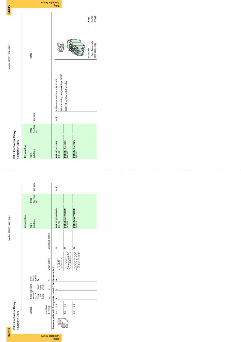
Com
plet
e un
its,
wit
h 1
earl
y-m
ake
cont
act,
1 la
te-b
reak
con
tact
2 M
2 B
64
1622
DIL
R22D
(230
V50
HZ)
0437
921
off
DIL
R22D
-G(2
4VD
C)04
8542
1 of
f Co
il te
rmin
al m
arki
ngs
to E
N50
005
Oth
er a
ctua
ting
volta
ges
a P
age
04/0
30
DILR
22D:
sup
plie
d w
ith fr
ont p
late
Acc
esso
ries
Page
1Am
plifi
er m
odul
e04
/026
Oth
er a
cces
sorie
s04
/026
4 M
4 B
44D
ILR4
4D(2
30V
50H
Z)04
3803
DIL
R44D
-G(2
4VD
C)04
8547
5 M
3 B
53D
ILR5
3D(2
30V
50H
Z)04
3814
DIL
R53D
-G(2
4VD
C)04
8552
141321 22
35 36
47 48
A1 A21
1413A1 A2
33 34
47 48
23 24
5161 62
52
7185
7286
1413A1 A2
33 34
47 48
23 24
53 54
6171 72
62
85 86
04/0
1404
/015
Moe
ller H
PL02
11-2
001/
2002
DIL
ET E
lect
roni
c Ti
min
g Re
lays
RelaysContactor Relays
RelaysContactor Relays
Moe
ller H
PL02
11-2
001/
2002
DIL
ET E
lect
roni
c Ti
min
g Re
lays
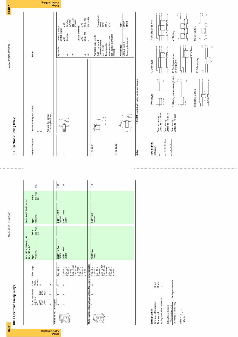
24 –
240
V, 5
0/60
Hz,
AC
24 –
240
V, D
C34
6 –
440V
, 50/
60 H
z, A
C
Rate
d op
erat
iona
l cu
rren
tIe
AC-1
1
Conv
. th
erm
. cu
rrent
I th
Tim
e ra
nge
Type
Pric
eTy
pePr
ice
Avai
labl
e fu
nctio
ns1)
Term
inal
mar
king
s to
EN
5004
2N
otes
Arti
cle
no.
See
Pric
e Li
stAr
ticle
no.
See
Pric
e Li
stSt
d.
220V
230V
240V
380V
400V
440V
AA
APo
tent
ial-f
ree
cont
act
Do n
ot a
pply
vol
tage
!
Tim
ing
rela
ys, O
n-de
laye
d3
36
1.5
– 30
sD
ILET
11-3
0-A
0488
78D
ILET
11-3
0-W
0489
041
off
11
33
60.
05 –
1 s
0.15
– 3
s0.
5 –
10 s
3 –
60 s
0.15
– 3
min
0.5
– 10
min
3 –
60 m
in0.
15 –
3 h
0.5
– 10
h3
– 60
h
DIL
ET11
-M-A
0488
86D
ILET
11-M
-W04
8891
1 of
f 11
Mul
ti-f
unct
ion
rela
y w
ith
conn
ecti
on fo
r re
mot
e po
tent
iom
eter
33
60.
05 –
1 s
0.15
– 3
s0.
5 –
10 s
3 –
60 s
0.15
– 3
min
0.5
– 10
min
3 –
60 m
in0.
15 –
3 h
0.5
– 10
h3
– 60
h
DIL
ET70
-A04
8893
DIL
ET70
-W04
8899
1 of
f 11
, 21,
42,
81
12, 1
6, 2
2, 8
2
Not
es1)
DI
LET1
1 su
pplie
d w
ith s
tate
d fu
nctio
n as
sta
ndar
d
A1 A2
15
1618
Type
suf
fixAc
tuat
ing
volta
gepr
inte
d on
uni
tV
DC
V AC
-A24
– 2
4024
– 2
40,
50/6
0 Hz
-W–
346
– 44
050
/60
HzVo
ltage
tole
ranc
e:V
DC
V AC
-A16
.8 –
288
20.4
– 2
64-W
–29
4.1
– 48
4
Adm
issib
le c
able
leng
th:
Cabl
e, u
nscr
eene
d Ca
ble
cros
s-se
ctio
n 0.
5 –
1.5
mm
2
Conn
ectio
n to
Y1/Y
2Z1
/Z2
Two-
core
cab
le25
0 m
Two-
core
cab
le in
sam
e ca
ble
duct
as
mai
ns c
able
50
/60
Hz
50 m
Acc
esso
ries
:Pa
geSe
alab
le s
hrou
d04
/027
Rem
ote
pote
ntio
met
er04
/028
A1 A2Z2Z1
15
1618
A1 A2Z2Z1
Y1 Y2
15
1618
Sett
ing
exam
ple
Flow
dia
gram
s11
On-
dela
yed
21 F
leet
ing
cont
act o
n en
ergi
zatio
n
81 P
ulse
gen
erat
ing
12 O
ff-de
laye
d
22 F
leet
ing
cont
act o
n de
-ene
rgiz
atio
n
82 P
ulse
sha
ping
16 O
n- a
nd O
ff-de
laye
d
42 F
lash
ing
ON
-OFF
func
tion
Tim
e ra
nge
of ti
min
g re
lay
60 m
inLE
D di
spla
yTi
me
requ
ired
42 m
inTi
me
t not
runn
ing
Cont
act 1
5 –
18 c
lose
d
Tim
e t r
unni
ngCo
ntac
t 15
– 18
clo
sed
Tim
e t r
unni
ngCo
ntac
t 15
– 18
ope
n
Sett
ing
requ
ired
on ti
me
scal
e7
Calc
ulat
ed a
s fo
llow
s:
LED
A1-A
2
15-1
8
t
A1-A
2
15-1
8
t
LED LED
A1-A
2
15-1
8
0.5
st
A1-A
2
Y1-Y
2
15-1
8t
LED A1-A
2
Y1-Y
2
15-1
8
t
LED
A1-A
2
Y1-Y
2
15-1
8
t
LED
A1-A
2
Y1-Y
2
15-1
8t
t
LED
LED
tt
tt
A1-A
2
15-1
8
A1-A
2
15-1
8
OFF
ON
OFF
LED
Tim
e re
quire
dx10
Tim
e ra
nge
of ti
min
g re
lay
---------
--------
---------
---------
--------
---------
--------
---------
Setti
ng o
n tim
e sc
ale
=
42 m
inx
10
60 m
in----
---------
--------
---------
7=
04/0
1604
/017
Moe
ller H
PL02
11-2
001/
2002
ETR4
Ele
ctro
nic
Tim
ing
Rela
ys
RelaysContactor Relays
RelaysContactor Relays
Moe
ller H
PL02
11-2
001/
2002
ETR4
Ele
ctro
nic
Tim
ing
Rela
ys
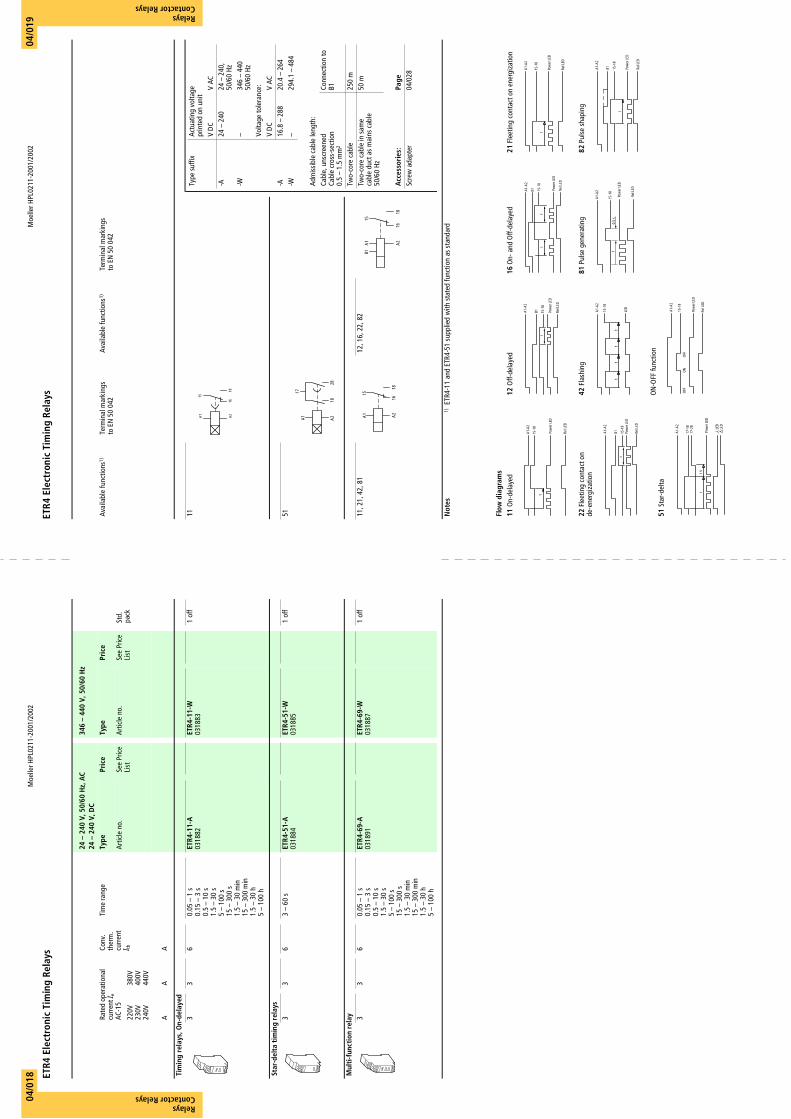
24 –
240
V, 5
0/60
Hz,
AC
24 –
240
V, D
C34
6 –
440
V, 5
0/60
Hz
Rate
d op
erat
iona
l cu
rren
t Ie
AC-1
5
Conv
. th
erm
. cu
rren
tI t
h
Tim
e ra
nge
Type
Pric
eTy
pePr
ice
Avai
labl
e fu
nctio
ns1)
Term
inal
mar
king
sto
EN
5004
2Av
aila
ble
func
tions
1)Te
rmin
al m
arki
ngs
to E
N50
042
Artic
le n
o.Se
e Pr
ice
List
Artic
le n
o.Se
e Pr
ice
List
Std.
pa
ck22
0V23
0V24
0V
380V
400V
440V
AA
A
Tim
ing
rela
ys, O
n-de
laye
d3
36
0.05
– 1
s0.
15 –
3 s
0.5
– 10
s1.
5 –
30 s
5 –
100
s15
– 3
00 s
1.5
– 30
min
15 –
300
min
1.5
– 30
h5
– 10
0 h
ETR4
-11-
A03
1882
ETR4
-11-
W03
1883
1 of
f 11
Star
-del
ta t
imin
g re
lays
33
63
– 60
sET
R4-5
1-A
0318
84ET
R4-5
1-W
0318
851
off
51
Mul
ti-f
unct
ion
rela
y 33
60.
05 –
1 s
0.15
– 3
s0.
5 –
10 s
1.5
– 30
s5
– 10
0 s
15 –
300
s1.
5 –
30 m
in15
– 3
00 m
in1.
5 –
30 h
5 –
100
h
ETR4
-69-
A03
1891
ETR4
-69-
W03
1887
1 of
f 11
, 21,
42,
81
12
, 16,
22,
82
Not
es1)
ET
R4-1
1 an
d ET
R4-5
1 su
pplie
d w
ith s
tate
d fu
nctio
n as
sta
ndar
d
A1 A2
15
1618
Type
suf
fixAc
tuat
ing
volta
gepr
inte
d on
uni
tV
DC
V AC
-A24
– 2
4024
– 2
40,
50/6
0 Hz
-W–
346
– 44
050
/60
HzVo
ltage
tole
ranc
e:V
DC
V AC
-A16
.8 –
288
20.4
– 2
64-W
–29
4.1
– 48
4
Adm
issib
le c
able
leng
th:
Cabl
e, u
nscr
eene
d Ca
ble
cros
s-se
ctio
n 0.
5 –
1.5
mm
2
Conn
ectio
n to
B1
Two-
core
cab
le25
0 m
Two-
core
cab
le in
sam
e ca
ble
duct
as
mai
ns c
able
50
/60
Hz
50 m
Acc
esso
ries
:Pa
geSc
rew
ada
pter
04/0
28
A1 A218
17
28
A1 A216
15
18
A1 A2
B115
1618
Flow
dia
gram
s11
On-
dela
yed
22 F
leet
ing
cont
act o
n de
-ene
rgiz
atio
n
51 S
tar-
delta
12 O
ff-de
laye
d
42 F
lash
ing
ON
-OFF
func
tion
16 O
n- a
nd O
ff-de
laye
d
81 P
ulse
gen
erat
ing
21 F
leet
ing
cont
act o
n en
ergi
zatio
n
82 P
ulse
sha
ping
A1-A
2
15-1
8
t
Rel L
ED
Pow
er L
ED
A1-A
2
B1 15-1
8t
Pow
er L
ED
Rel L
ED
17-1
8
tt
u
A1-A
2
17-2
8
Pow
er L
ED
L
ED
LED
Rel L
ED
A1-A
2
B1 15-1
8t
Pow
er L
ED
LED
tt
tt
A1-A
2
15-1
8
15-1
8
A1-A
2
OFF
ON
OFF
Rel L
ED
Pow
er L
ED
A1-A
2
B1 15-1
8t
t
Pow
er L
ED
Rel L
ED
t
A1-A
2
15-1
80.
5 s
Rel L
ED
Pow
er L
ED
A1-A
2
15-1
8t
Rel L
ED
Pow
er L
ED
A1-A
2
B1 15-1
8t
Pow
er L
ED
Rel L
ED
04/0
1904
/018
Moeller HPL0211-2001/2002
ETR4 Electronic Timing Relays
Rela
ysCo
ntac
tor R
elay
s04/020
24 – 240 V, 50/60 Hz, AC24 – 240 V, DC
Rated operational current IeAC-11
Conv. therm.currentIth
Time range Type Price NotesArticle no. See Price
ListStd. pack
220 V230 V240 V
380 V400 V440 V
A A A
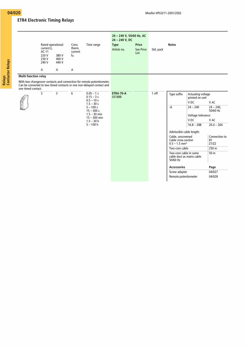
Multi-function relay
With two changeover contacts and connection for remote potentiometer. Can be converted to two timed contacts or one non-delayed contact and one timed contact.
3 3 6 0.05 – 1 s0.15 – 3 s0.5 – 10 s1.5 – 30 s5 – 100 s15 – 300 s1.5 – 30 min15 – 300 min1.5 – 30 h5 – 100 h
ETR4-70-A031888
1 off Type suffix Actuating voltageprinted on unitV DC V AC
-A 24 – 240 24 – 240,50/60 Hz
Voltage tolerance:V DC V AC16.8 – 288 20.4 – 264
Admissible cable length:Cable, unscreened Cable cross-section 0.5 – 1.5 mm2
Connection toB1Z1/Z2
Two-core cable 250 mTwo-core cable in same cable duct as mains cable 50/60 Hz
50 m
Accessories PageScrew adapter 04/027Remote potentiometer 04/028
Rela
ysCo
ntac
tor
Rela
ys
Moeller HPL0211-2001/2002
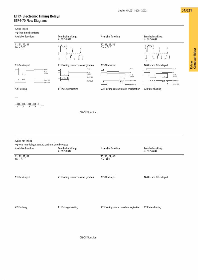
ETR4 Electronic Timing RelaysETR4-70 Flow Diagrams
04/021
A2/X1 linkeda Two timed contactsAvailable functions Terminal markings
to EN 50 042Available functions Terminal markings
to EN 50 042
11, 21, 42, 81ON – OFF
12, 16, 22, 82ON – OFF
11 On-delayed 21 Fleeting contact on energization 12 Off-delayed 16 On- and Off-delayed
42 Flashing 81 Pulse generating 22 Fleeting contact on de-energization 82 Pulse shaping
ON-OFF function
A2/X1 not linkeda One non-delayed contact and one timed contactAvailable functions Terminal markings
to EN 50 042Available functions Terminal markings
to EN 50 042
11, 21, 42, 81ON – OFF
12, 16, 22, 82ON - OFF
11 On-delayed 21 Fleeting contact on energization 12 Off-delayed 16 On- and Off-delayed
42 Flashing 81 Pulse generating 22 Fleeting contact on de-energization 82 Pulse shaping
ON-OFF function
A1
A2X1
Z2Z1
15
16 18
25
26 28
A1
A2X1
Z2Z1
15
16 18
25
26 28
B1
(25-28)
A1-A2
15-18
t
Power LED
Rel 1,2 LED
A1-A2
t (25-28)15-18
Rel 1,2 LED
Power LED
A1-A2
B1
15-18
t (25-28)
Power LED
Rel 1,2 LED
A1-A2
B1
tt (25-28)15-18
Power LED
Rel 1,2 LED
A1-A2
15-18
t t t t
(25-28)
Rel 1,2 LED
Power LED
15-18
A
1
-
A
2
0
,
5
s
t
(25-28)
Rel 1,2 LED
Power LED
A1-A2
B1
t
(25-28)15-18
Rel 1,2 LEDPower LED
15-18A1-A2B1
t (25-28)
Rel 1,2 LEDPower LED
15-18
(25-28)
A1-A2Rel 1,2 LEDOFF
ONOFF
Power LED
A1
A2
X1
Z1 Z2
1516
18
2122
24
A1
A2
X1
Z1 Z2
1516 18
2122
24
B1
A1-A215-18
t
21-24
Power LED
Rel 1 LEDRel 2 LED
15-18
t
21-24A1-A2Rel 1 LEDPower LEDRel 2 LEDA1-A2B115-18t 21-24Power LEDRel 1 LEDRel 2 LEDA1-A2B115-18tt 21-24Power LED
Rel 1 LEDRel 2 LED
15-18
t t t t
2 1 - 2 4A 1 - A 2A 1 - A 2 R e l 2 L E D R e l 1 L E D
P o w e r L E D
A 1 - A 21 5 - 1 80 . 5 s
t
2 1 - 2 4
R e l 1 L E DP o w e r L E D
R e l 2 L E D
A 1 - A 2
B 1 1 5 - 1 8t
2 1 - 2 4 R e l 1 L E DP o w e r L E D
R e l 2 L E D
B 1A 1 - A 2
1 5 - 1 8
t
2 1 - 2 4
R e l 1 L E DP o w e r L E D R e l 2 L E D
1 5 - 1 8( 2 5 - 2 8 )A 1 - A 2R e l 1 , 2 L E D
O F F
O N O F FP o w e r L E D
Moeller HPL0211-2001/2002
ESR Electronic Safety RelaysEngineering
Rela
ysCo
ntac
tor R
elay
s04/022
Electronic safety relays are used for monitoring safety-related control systems. The requirements for the electrical equipment of machines are specified in IEC/EN 60 204. EN 954-1 stipulates that machine users must carry out a risk assessment of machines and implement a control system that meets the requirements of safety categories 1, 2, 3, or 4.
The electronic safety relays consist of a power section, the electronics and two redundant relays with interlocked opposing contacts for the enabling- and signalling paths.
The range includes relays for:
Contact expansion modules with andwithout time delay are also available.
The ESR electronic safety relays are approved by employers' liability associations and meet the requirements of safety category 3 or 4. The safety category of the control system is determined by the combination with the external circuitry, for which the machine operator is responsible.The electronic safety relays are single-fault proof, i.e. one fault in the safety circuit does not cause hazardous conditions. EN 954-1 excludes the possibility of two independent faults occurring at the same time.
IEC/EN 60 204-1 stipulates two relevant stop categories for stopping in the event of an emergency:
• Stop category 0: stopping by means of immediate removal of the power supply to the machine actuators.
• Stop category 1: controlled stopping with power available to the machine actuators to achieve the stop. Power is not removed until the stop is achieved.
The safety relays for Emergency-Stop applications and the non-delayed expansion modules are suitable for Stop category 0. Delayed contact expansion modules meet the requirements of Stop category 1.
In fault-free operation, following the starting command, the safety circuits are monitored by the electronics, and the enabling paths are activated via the relay. Following the switch Off command, and also in the event of a fault (earth fault, faulty insulation, wire breakage etc.), the enabling paths are blocked immediately (stop category 0) or with a time delay (stop category 1), and the motor is disconnected from the power supply. Since a short circuit in the redundant safety circuit does not cause a hazardous condition, the fault is not detected until the system is reset, when switching On is prevented..
Safety relays for stopping in the event of an emergency and for monitoring of protective guards are available for single-channel and dual-channel applications. The single-channel construction enables earth-fault monitoring to be implemented for the safety circuit. The dual-channel application provides a redundant Emergency-Stop or protective guard monitoring circuit. This allows monitoring for short circuits and cable insulation faults to be implemented additionally. The device can also be used with or without reset monitoring. In this way, the device is not started and enabling paths switched until the falling edge of the On push-button has been detected. An application for the device without reset monitoring is for example, for monitoring protective doors for an automatic restart.
Applications
Construction
Product range overview
Emergency-Stop circuits
Monitoring of contact mats/safety mats, and safety bumpers
Protective guard monitoring
Monitoring of two-hand controls
Rela
ysCo
ntac
tor
Rela
ys
Moeller HPL0211-2001/2002
ESR Electronic Safety Relays Basic Units, Contact Expansion Modules
04/023
Actuating voltage Uc
Safety category toEN 954-1
Enabling pathtoIEC/EN 60 204
Type PriceArticle no. See Price List Std. pack
Stop category0 1
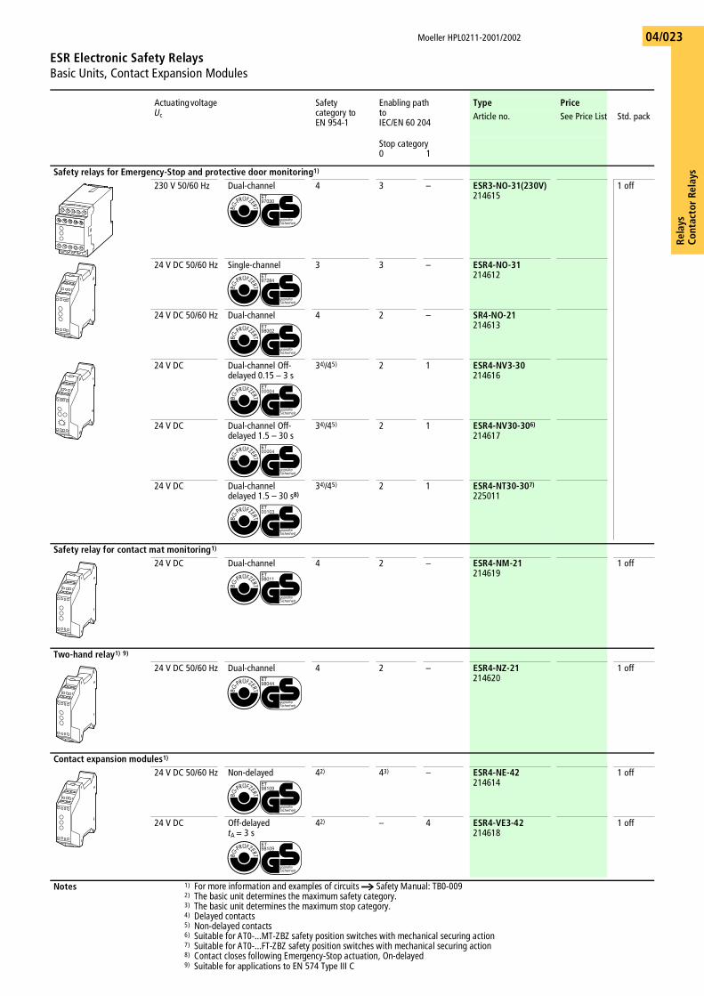
Safety relays for Emergency-Stop and protective door monitoring1)
230 V 50/60 Hz Dual-channel 4 3 – ESR3-NO-31(230V)214615
1 off
24 V DC 50/60 Hz Single-channel 3 3 – ESR4-NO-31214612
24 V DC 50/60 Hz Dual-channel 4 2 – SR4-NO-21214613
24 V DC Dual-channel Off-delayed 0.15 – 3 s
34)/45) 2 1 ESR4-NV3-30214616
24 V DC Dual-channel Off-delayed 1.5 – 30 s
34)/45) 2 1 ESR4-NV30-306)
214617
24 V DC Dual-channel delayed 1.5 – 30 s8)
34)/45) 2 1 ESR4-NT30-307)
225011
Safety relay for contact mat monitoring1)
24 V DC Dual-channel 4 2 – ESR4-NM-21214619
1 off
Two-hand relay1) 9)
24 V DC 50/60 Hz Dual-channel 4 2 – ESR4-NZ-21214620
1 off
Contact expansion modules1)
24 V DC 50/60 Hz Non-delayed 42) 43) – ESR4-NE-42214614
1 off
24 V DC Off-delayedtA = 3 s
42) – 4 ESR4-VE3-42214618
1 off
Notes 1) For more information and examples of circuits a Safety Manual: TB0-0092) The basic unit determines the maximum safety category.3) The basic unit determines the maximum stop category.4) Delayed contacts5) Non-delayed contacts6) Suitable for AT0-...MT-ZBZ safety position switches with mechanical securing action7) Suitable for AT0-...FT-ZBZ safety position switches with mechanical securing action8) Contact closes following Emergency-Stop actuation, On-delayed9) Suitable for applications to EN 574 Type III C
Moeller HPL0211-2001/2002
EMR4 Measuring and Monitoring RelaysCurrent Monitoring Relays, Phase Sequence Relays, Phase Monitoring Relays, Phase Imbalance Monitoring Relays
Rela
ysCo
ntac
tor R
elay
s04/024
Description Adjustable current measuring rangeI~/I=
Circuit symbol Supplyvoltage
Type Price Std. pack
Article no. See Price List
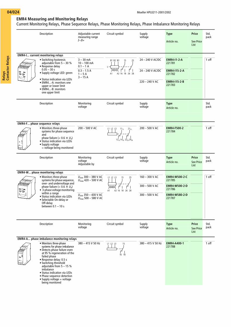
EMR4-I... current monitoring relays• Switching hysteresis
adjustable from 5 – 30 %• Response delay
0.05 – 30 s• Supply voltage LED: green
• Status indication via LEDs• EMR4...-A: monitors one
upper or lower limit• EMR4...-B: monitors
one upper limit
3 – 30 mA10 – 100 mA0.1 – 1 A
24 – 240 V AC/DC EMR4-I1-2-A221781
1 off
0.3 – 1.5 A1 – 5 A3 – 15 A
24 – 240 V AC/DC EMR4-I15-2-A221782
220 – 240 V AC EMR4-I15-2-B221783
Description Monitoringvoltage
Circuit symbol Supplyvoltage
Type Std. packArticle no.
EMR4-F... phase sequence relays• Monitors three-phase
systems for phase sequence and phase failure (< 0.6 X Ue)
• Status indication via LEDs• Supply voltage
= voltage being monitored
200 – 500 V AC 200 – 500 V AC EMR4-F500-2221784
1 off
Description MonitoringvoltageAdjustable by
Circuit symbol Supplyvoltage
Type Price Std. packArticle no. See Price
List
EMR4-W... phase monitoring relays• Monitors three-phase
systems for phase sequence, over- and undervoltage and phase failure (< 0.6 X Ue)
• 3-phase voltage monitoring within a range
• Status indication via LEDs• Selectable On-delay or
Off-delay between 0.1 – 10 s
Umin 300 – 380 V ACUmax 420 – 500 V AC
160 – 300 V AC EMR4-W500-2-C221785
1 off
300 – 500 V AC EMR4-W500-2-D221786
Umin 350 – 430 V ACUmax 500 – 580 V AC
300 – 500 V AC EMR4-W580-2-D221787
Description Monitoringvoltage
Circuit symbol Supplyvoltage
Type Price Std. packArticle no. See Price
List
EMR4-A... phase imbalance monitoring relays• Monitors three-phase
systems for phase imbalance• Detects phase failure even
at 95 % regeneration of the failed phase
• Response delay: 0.5 s• Switching threshold
adjustable from 5 – 15 % imbalance
• Status indication via LEDs• Phase sequence detection• Supply voltage = voltage
being monitored
380 – 415 V 50 Hz 380 – 415 V 50 Hz EMR4-A400-1221788
1 off
C
15 25B1 B2 B3
1816 26 28A1 A2
15L1 L2 L3 11
1612 1814 2622 2824
2521
15 25L1 L2 L3
1816 26 28A1 A2
L1 L2 L3 15
16 18
Rela
ysCo
ntac
tor
Rela
ys
Moeller HPL0211-2001/2002
EMR4 Measuring and Monitoring RelaysLevel Monitoring Relays, Insulation Monitoring Relays, Sealable Shrouds
04/025
Description Responsesensitivity range
Circuit symbol Supplyvoltage
Type Price Std. pack
Article no. See Price List
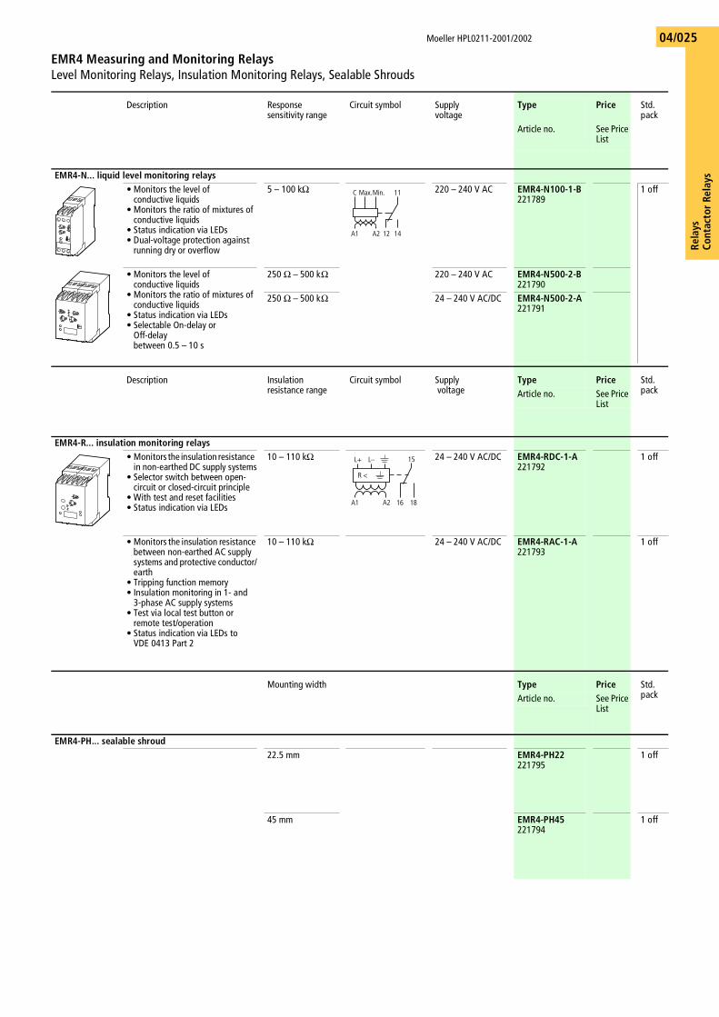
EMR4-N... liquid level monitoring relays• Monitors the level of
conductive liquids• Monitors the ratio of mixtures of
conductive liquids• Status indication via LEDs• Dual-voltage protection against
running dry or overflow
5 – 100 kO 220 – 240 V AC EMR4-N100-1-B221789
1 off
• Monitors the level of conductive liquids
• Monitors the ratio of mixtures of conductive liquids
• Status indication via LEDs• Selectable On-delay or
Off-delaybetween 0.5 – 10 s
250 O – 500 kO 220 – 240 V AC EMR4-N500-2-B221790
250 O – 500 kO 24 – 240 V AC/DC EMR4-N500-2-A221791
Description Insulation resistance range
Circuit symbol Supply voltage
Type Price Std. packArticle no. See Price
List
EMR4-R... insulation monitoring relays• Monitors the insulation resistance
in non-earthed DC supply systems• Selector switch between open-
circuit or closed-circuit principle• With test and reset facilities• Status indication via LEDs
10 – 110 kO 24 – 240 V AC/DC EMR4-RDC-1-A221792
1 off
• Monitors the insulation resistance between non-earthed AC supply systems and protective conductor/earth
• Tripping function memory• Insulation monitoring in 1- and
3-phase AC supply systems• Test via local test button or
remote test/operation• Status indication via LEDs to
VDE 0413 Part 2
10 – 110 kO 24 – 240 V AC/DC EMR4-RAC-1-A221793
1 off
Mounting width Type Price Std. packArticle no. See Price
List
EMR4-PH... sealable shroud22.5 mm EMR4-PH22
2217951 off
45 mm EMR4-PH45221794
1 off
11C Max.Min.
1412A1 A2
15L+
R <
L–
1816A1 A2
Moeller HPL0211-2001/2002
Mini Contactor Relays, Contactor RelaysAccessories
Rela
ysCo
ntac
tor R
elay
s04/026
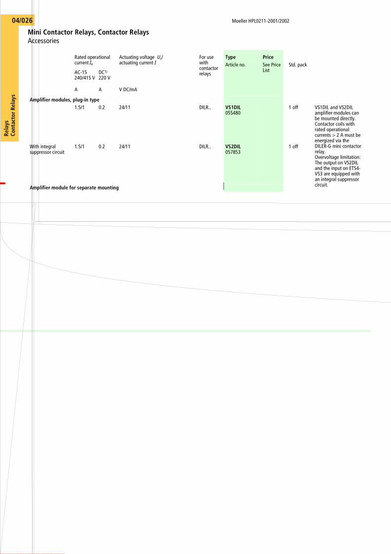
Rated operational current Ie
Actuating voltage Us/actuating current I
For use with contactor relays
Type PriceArticle no. See Price
ListStd. pack
AC-15240/415 V
DC1)
220 V
A A V DC/mA
Amplifier modules, plug-in type1.5/1 0.2 24/11 DILR.. VS1DIL
0554801 off VS1DIL and VS2DIL
amplifier modules can be mounted directly. Contactor coils with rated operational currents > 2 A must be energized via theDILER-G mini contactor relay. Overvoltage limitation: The output on VS2DIL and the input on ETS4-VS3 are equipped with an integral suppressor circuit.
With integral suppressor circuit
1.5/1 0.2 24/11 DILR.. VS2DIL057853
1 off
Amplifier module for separate mounting
Rela
ysCo
ntac
tor
Rela
ys
Moeller HPL0211-2001/2002
Mini Contactor Relays, Contactor Relays, Electronic Timing RelaysAccessories
04/027
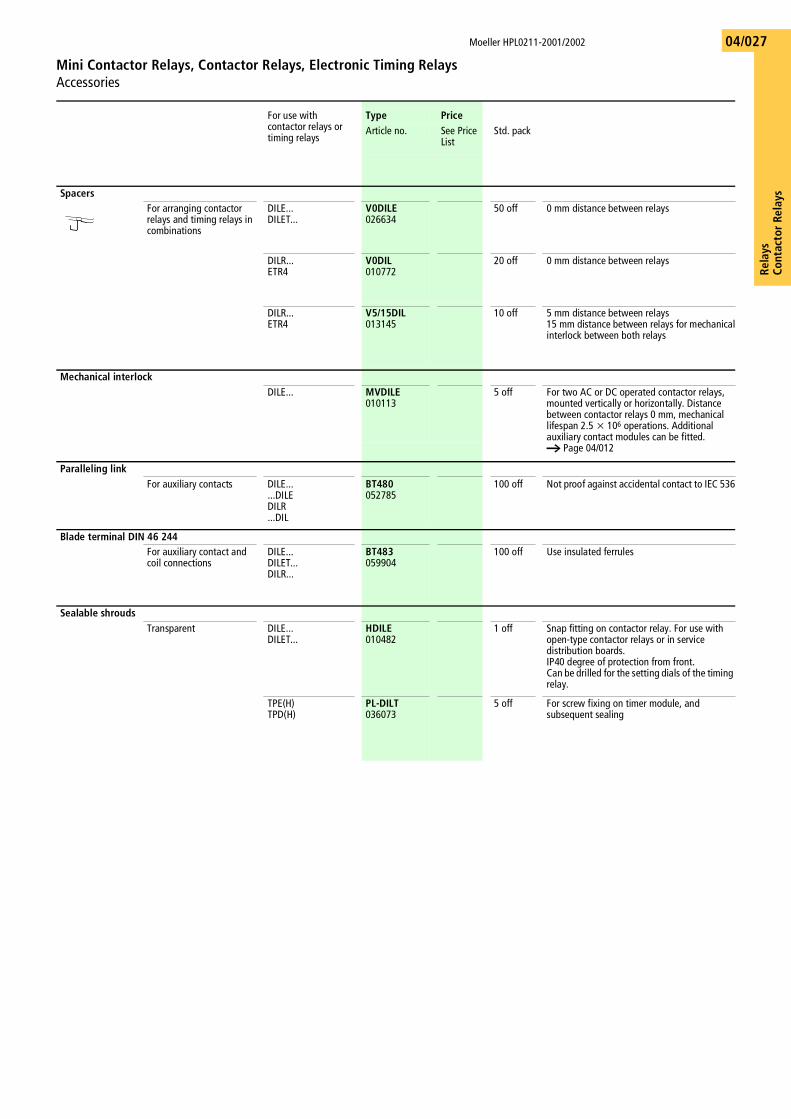
For use with contactor relays or timing relays
Type PriceArticle no. See Price
ListStd. pack
SpacersFor arranging contactorrelays and timing relays in combinations
DILE...DILET...
V0DILE026634
50 off 0 mm distance between relays
DILR...ETR4
V0DIL010772
20 off 0 mm distance between relays
DILR...ETR4
V5/15DIL013145
10 off 5 mm distance between relays15 mm distance between relays for mechanicalinterlock between both relays
Mechanical interlockDILE... MVDILE
0101135 off For two AC or DC operated contactor relays,
mounted vertically or horizontally. Distance between contactor relays 0 mm, mechanical lifespan 2.5 x 10⁶ operations. Additional auxiliary contact modules can be fitted. a Page 04/012
Paralleling linkFor auxiliary contacts DILE...
...DILEDILR...DIL
BT480052785
100 off Not proof against accidental contact to IEC 536
Blade terminal DIN 46 244For auxiliary contact andcoil connections
DILE...DILET...DILR...
BT483059904
100 off Use insulated ferrules
Sealable shroudsTransparent DILE...
DILET...HDILE010482
1 off Snap fitting on contactor relay. For use with open-type contactor relays or in service distribution boards.IP40 degree of protection from front.Can be drilled for the setting dials of the timing relay.
TPE(H)TPD(H)
PL-DILT036073
5 off For screw fixing on timer module, and subsequent sealing
Moeller HPL0211-2001/2002
Mini Contactor Relays, Contactor Relays, Electronic Timing RelaysAccessories
Rela
ysCo
ntac
tor R
elay
s04/028
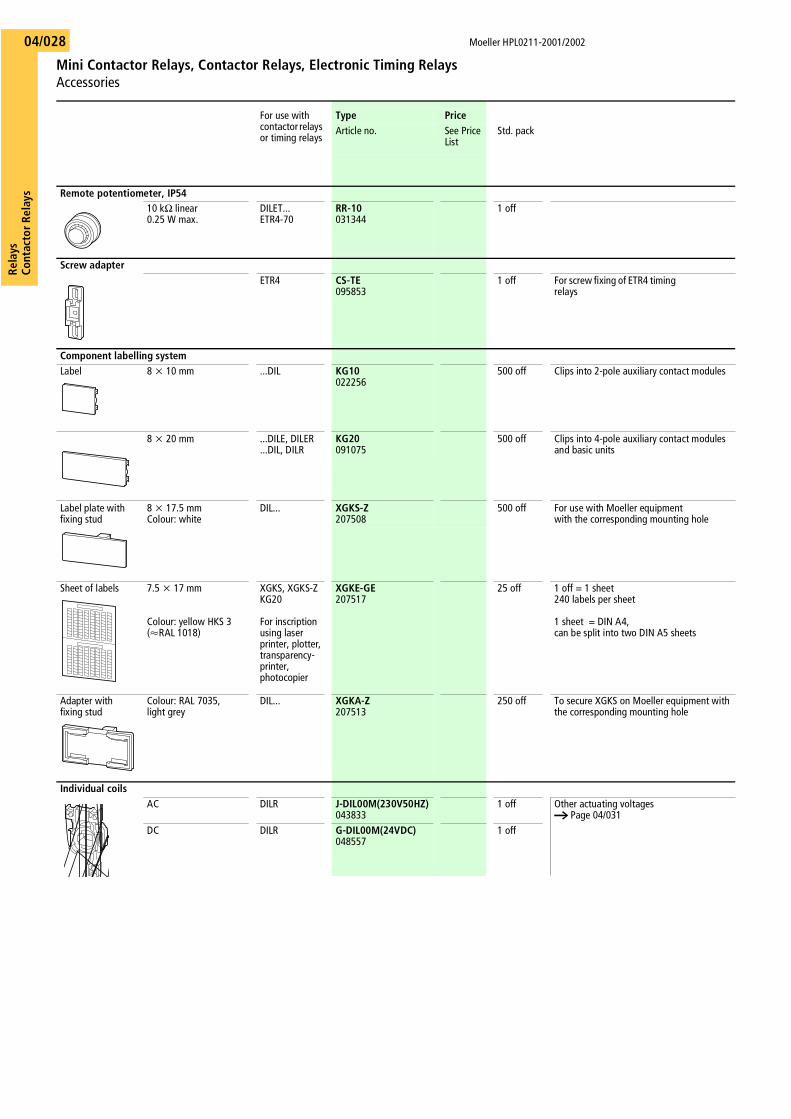
For use with contactor relays or timing relays
Type PriceArticle no. See Price
ListStd. pack
Remote potentiometer, IP5410 kO linear 0.25 W max.
DILET...ETR4-70
RR-10031344
1 off
Screw adapterETR4 CS-TE
0958531 off For screw fixing of ETR4 timing
relays
Component labelling systemLabel 8 x 10 mm ...DIL KG10
022256500 off Clips into 2-pole auxiliary contact modules
8 x 20 mm ...DILE, DILER ...DIL, DILR
KG20091075
500 off Clips into 4-pole auxiliary contact modules and basic units
Label plate with fixing stud
8 x 17.5 mmColour: white
DIL... XGKS-Z207508
500 off For use with Moeller equipmentwith the corresponding mounting hole
Sheet of labels 7.5 x 17 mm
Colour: yellow HKS 3(QRAL 1018)
XGKS, XGKS-ZKG20
For inscription using laser printer, plotter, transparency-printer, photocopier
XGKE-GE207517
25 off 1 off = 1 sheet240 labels per sheet
1 sheet = DIN A4,can be split into two DIN A5 sheets
Adapter with fixing stud
Colour: RAL 7035, light grey
DIL... XGKA-Z207513
250 off To secure XGKS on Moeller equipment with the corresponding mounting hole
Individual coilsAC DILR J-DIL00M(230V50HZ)
0438331 off Other actuating voltages
a Page 04/031DC DILR G-DIL00M(24VDC)
0485571 off
Rela
ysCo
ntac
tor
Rela
ys
Moeller HPL0211-2001/2002
Mini Contactor Relays, Contactor relaysContact Travel Diagrams
04/029
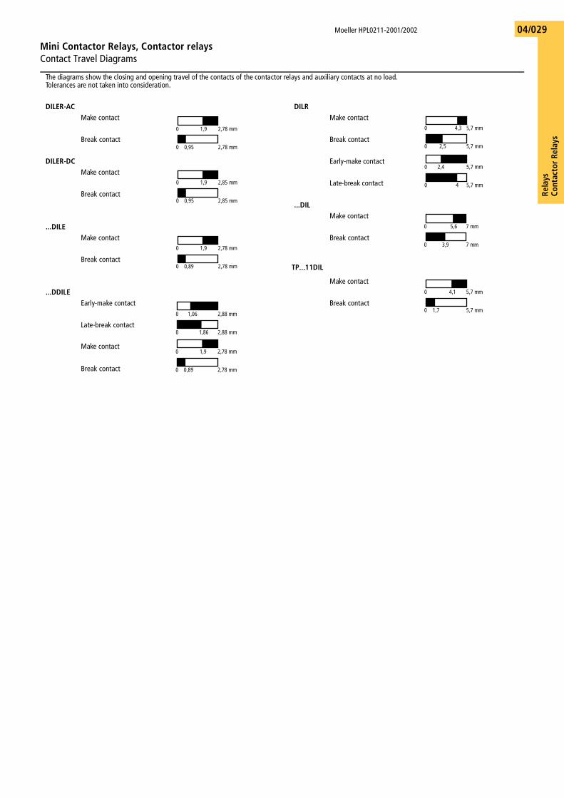
The diagrams show the closing and opening travel of the contacts of the contactor relays and auxiliary contacts at no load. Tolerances are not taken into consideration.
DILER-AC DILRMake contact Make contact
Break contact Break contact
DILER-DC Early-make contactMake contact
Late-break contactBreak contact
...DILMake contact
...DILEMake contact Break contact
Break contactTP...11DIL
Make contact...DDILE
Early-make contact Break contact
Late-break contact
Make contact
Break contact
0 1,9 2,78 mm
0 0,95 2,78 mm
0 4,3 5,7 mm
0 2,5 5,7 mm
0 2,4 5,7 mm
0 4 5,7 mm0 1,9 2,85 mm
0 0,95 2,85 mm
0 5,6 7 mm
0 3,9 7 mm0 1,9 2,78 mm
0 0,89 2,78 mm
0 4,1 5,7 mm
0 1,7 5,7 mm0 1,06 2,88 mm
0 1,86 2,88 mm
0 1,9 2,78 mm
0 0,89 2,78 mm
Moeller HPL0211-2001/2002
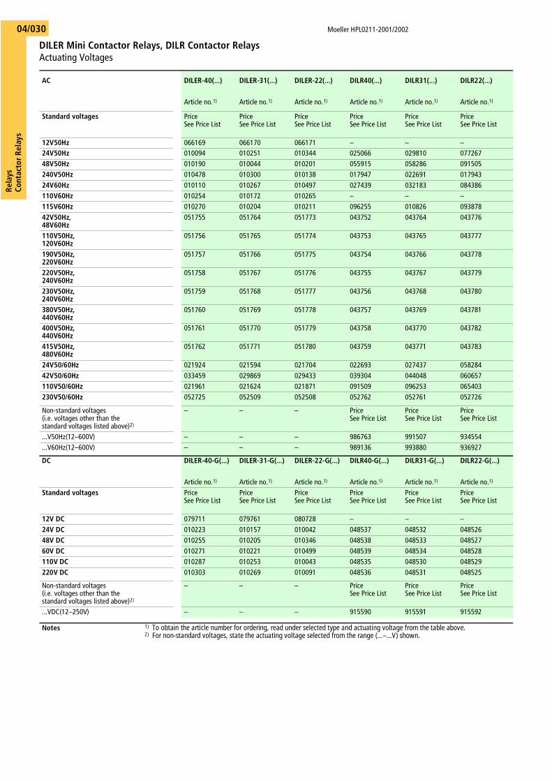
DILER Mini Contactor Relays, DILR Contactor Relays Actuating Voltages
Rela
ysCo
ntac
tor R
elay
s04/030
AC DILER-40(...) DILER-31(...) DILER-22(...) DILR40(...) DILR31(...) DILR22(...)
Article no.1) Article no.1) Article no.1) Article no.1) Article no.1) Article no.1)
Standard voltages PriceSee Price List
PriceSee Price List
PriceSee Price List
PriceSee Price List
PriceSee Price List
PriceSee Price List
12V50Hz 066169 066170 066171 – – –24V50Hz 010094 010251 010344 025066 029810 07726748V50Hz 010190 010044 010201 055915 058286 091505240V50Hz 010478 010300 010138 017947 022691 01794324V60Hz 010110 010267 010497 027439 032183 084386110V60Hz 010254 010172 010265 – – –115V60Hz 010270 010204 010211 096255 010826 09387842V50Hz, 48V60Hz
051755 051764 051773 043752 043764 043776
110V50Hz, 120V60Hz
051756 051765 051774 043753 043765 043777
190V50Hz, 220V60Hz
051757 051766 051775 043754 043766 043778
220V50Hz, 240V60Hz
051758 051767 051776 043755 043767 043779
230V50Hz, 240V60Hz
051759 051768 051777 043756 043768 043780
380V50Hz, 440V60Hz
051760 051769 051778 043757 043769 043781
400V50Hz, 440V60Hz
051761 051770 051779 043758 043770 043782
415V50Hz, 480V60Hz
051762 051771 051780 043759 043771 043783
24V50/60Hz 021924 021594 021704 022693 027437 05828442V50/60Hz 033459 029869 029433 039304 044048 060657110V50/60Hz 021961 021624 021871 091509 096253 065403230V50/60Hz 052725 052509 052508 052762 052761 052726
Non-standard voltages(i.e. voltages other than the standard voltages listed above)2)
– – – PriceSee Price List
PriceSee Price List
PriceSee Price List
...V50Hz(12–600V) – – – 986763 991507 934554
...V60Hz(12–600V) – – – 989136 993880 936927
DC DILER-40-G(...) DILER-31-G(...) DILER-22-G(...) DILR40-G(...) DILR31-G(...) DILR22-G(...)
Article no.1) Article no.1) Article no.1) Article no.1) Article no.1) Article no.1)
Standard voltages PriceSee Price List
PriceSee Price List
PriceSee Price List
PriceSee Price List
PriceSee Price List
PriceSee Price List
12V DC 079711 079761 080728 – – –24V DC 010223 010157 010042 048537 048532 04852648V DC 010255 010205 010346 048538 048533 04852760V DC 010271 010221 010499 048539 048534 048528110V DC 010287 010253 010043 048535 048530 048529220V DC 010303 010269 010091 048536 048531 048525
Non-standard voltages(i.e. voltages other than thestandard voltages listed above)2)
– – – PriceSee Price List
PriceSee Price List
PriceSee Price List
...VDC(12–250V) – – – 915590 915591 915592
Notes 1) To obtain the article number for ordering, read under selected type and actuating voltage from the table above.2) For non-standard voltages, state the actuating voltage selected from the range (...–...V) shown.
Rela
ysCo
ntac
tor
Rela
ys
Moeller HPL0211-2001/2002
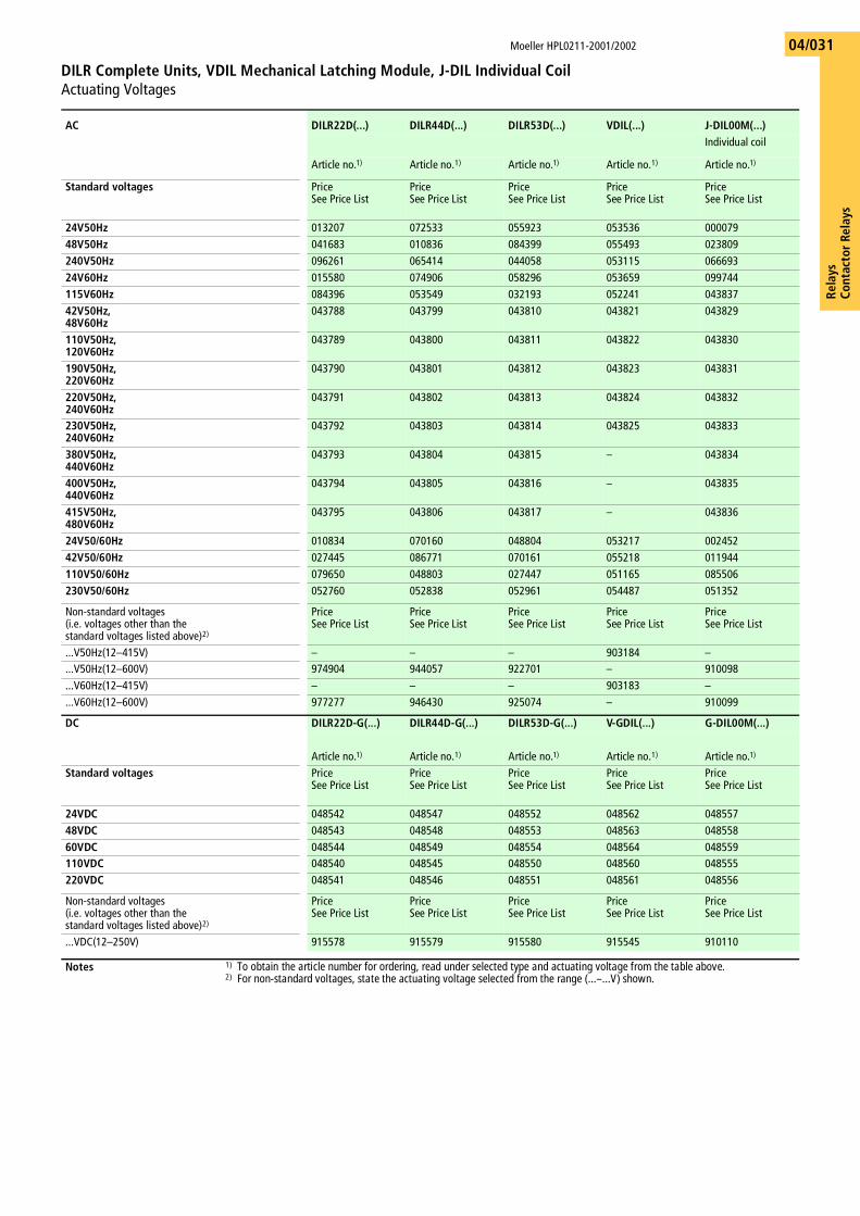
DILR Complete Units, VDIL Mechanical Latching Module, J-DIL Individual CoilActuating Voltages
04/031
AC DILR22D(...) DILR44D(...) DILR53D(...) VDIL(...) J-DIL00M(...)Individual coil
Article no.1) Article no.1) Article no.1) Article no.1) Article no.1)
Standard voltages PriceSee Price List
PriceSee Price List
PriceSee Price List
PriceSee Price List
PriceSee Price List
24V50Hz 013207 072533 055923 053536 00007948V50Hz 041683 010836 084399 055493 023809240V50Hz 096261 065414 044058 053115 06669324V60Hz 015580 074906 058296 053659 099744115V60Hz 084396 053549 032193 052241 04383742V50Hz, 48V60Hz
043788 043799 043810 043821 043829
110V50Hz, 120V60Hz
043789 043800 043811 043822 043830
190V50Hz, 220V60Hz
043790 043801 043812 043823 043831
220V50Hz, 240V60Hz
043791 043802 043813 043824 043832
230V50Hz, 240V60Hz
043792 043803 043814 043825 043833
380V50Hz, 440V60Hz
043793 043804 043815 – 043834
400V50Hz, 440V60Hz
043794 043805 043816 – 043835
415V50Hz, 480V60Hz
043795 043806 043817 – 043836
24V50/60Hz 010834 070160 048804 053217 00245242V50/60Hz 027445 086771 070161 055218 011944110V50/60Hz 079650 048803 027447 051165 085506230V50/60Hz 052760 052838 052961 054487 051352
Non-standard voltages(i.e. voltages other than thestandard voltages listed above)2)
PriceSee Price List
PriceSee Price List
PriceSee Price List
PriceSee Price List
PriceSee Price List
...V50Hz(12–415V) – – – 903184 –
...V50Hz(12–600V) 974904 944057 922701 – 910098
...V60Hz(12–415V) – – – 903183 –
...V60Hz(12–600V) 977277 946430 925074 – 910099
DC DILR22D-G(...) DILR44D-G(...) DILR53D-G(...) V-GDIL(...) G-DIL00M(...)
Article no.1) Article no.1) Article no.1) Article no.1) Article no.1)
Standard voltages PriceSee Price List
PriceSee Price List
PriceSee Price List
PriceSee Price List
PriceSee Price List
24VDC 048542 048547 048552 048562 04855748VDC 048543 048548 048553 048563 04855860VDC 048544 048549 048554 048564 048559110VDC 048540 048545 048550 048560 048555220VDC 048541 048546 048551 048561 048556
Non-standard voltages(i.e. voltages other than thestandard voltages listed above)2)
PriceSee Price List
PriceSee Price List
PriceSee Price List
PriceSee Price List
PriceSee Price List
...VDC(12–250V) 915578 915579 915580 915545 910110
Notes 1) To obtain the article number for ordering, read under selected type and actuating voltage from the table above.2) For non-standard voltages, state the actuating voltage selected from the range (...–...V) shown.
Moeller HPL0211-2001/2002
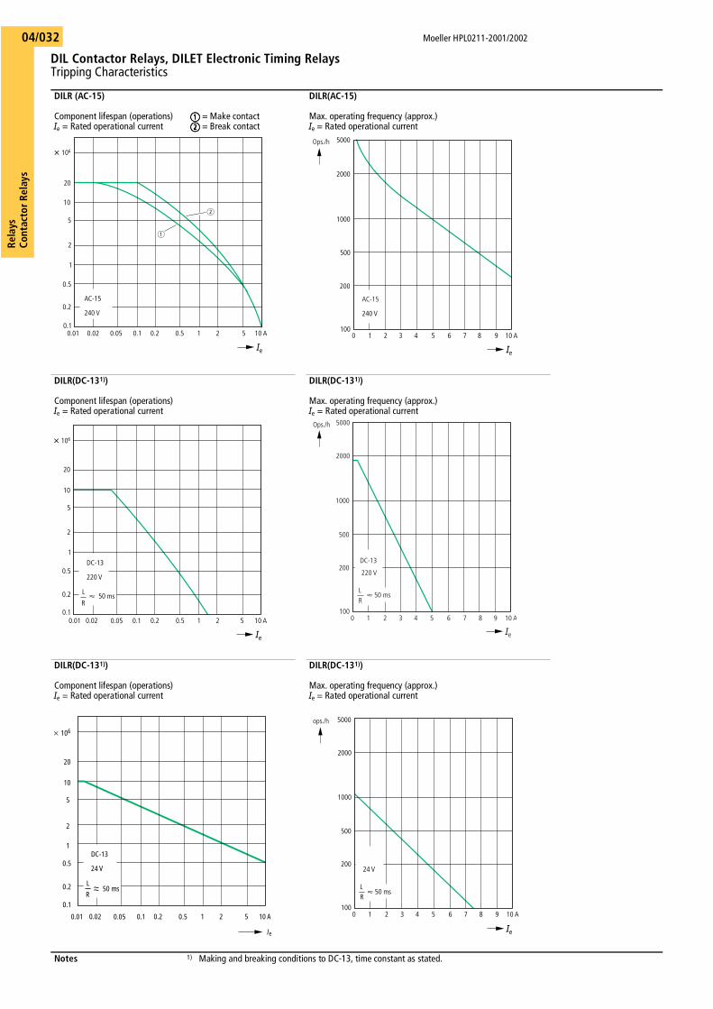
DIL Contactor Relays, DILET Electronic Timing RelaysTripping Characteristics
Rela
ysCo
ntac
tor R
elay
s04/032
DILR (AC-15)
Component lifespan (operations)Ie = Rated operational current
aaaa = Make contactbbbb = Break contact
DILR(AC-15)
Max. operating frequency (approx.)Ie = Rated operational current
DILR(DC-131))
Component lifespan (operations)Ie = Rated operational current
DILR(DC-131))
Max. operating frequency (approx.)Ie = Rated operational current
DILR(DC-131))
Component lifespan (operations)Ie = Rated operational current
DILR(DC-131))
Max. operating frequency (approx.)Ie = Rated operational current
Notes 1) Making and breaking conditions to DC-13, time constant as stated.
AC-15
240 V
0.01 0.050.02 20.1 0.5 10.2 5 10 A
20
10
5
2
1
0.5
0.2
0.1
X 106
a
b
Ie
5000
240 V
2000
1000
500
200
0 21 73 5 64 8 10 A9100
Ie
AC-15
Ops./h
0.01 0.050.02 20.1 0.5 10.2 5 10 A
20
10
5
2
1
0.5
0.2
0.1
X 106
L
R
DC-13
220 V
Q 50 ms
Ie
LR
220 V
0 10 A987654321
5000
2000
1000
500
200
100
Ie
DC-13
Q 50 ms
Ops./h
0.01 0.050.02 20.1 0.5 10.2 5 10 A
20
10
5
2
1
0.5
0.2
0.1
� 106
L
R
DC-13
24 V
50 ms
el
LR
24 V
Q 50 ms
0 10 A987654321
5000
2000
1000
500
200
100
Ie
ops./h
Rela
ysCo
ntac
tor
Rela
ys
Moeller HPL0211-2001/2002
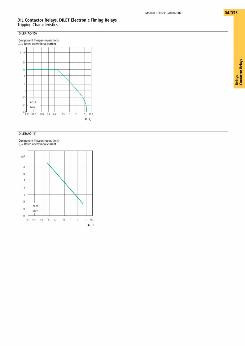
DIL Contactor Relays, DILET Electronic Timing RelaysTripping Characteristics
04/033
DILER(AC-15)
Component lifespan (operations)Ie = Rated operational current
DILET(AC-11)
Component lifespan (operations)Ie = Rated operational current
AC-15
240 V
0.01 0.050.02 20.1 0.5 10.2 5 10 A
20
10
5
2
1
0.5
0.2
0.1
x 106
Ie
AC-11
240 V
0.01 0.050.02 20.1 0.5 10.2 5 10 A
20
10
5
2
1
0.5
0.2
0.1
x 10 6
e
Moeller HPL0211-2001/2002
EMR4 Measuring and Monitoring Relays Tripping Characteristics
Rela
ysCo
ntac
tor R
elay
s04/034
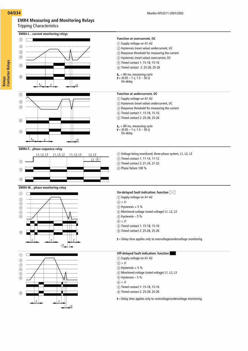
EMR4-I... current monitoring relays Function at overcurrent, OCa Supply voltage on A1-A2b Hysteresis (reset value) undercurrent, UCc Response threshold for measuring the currentd Hysteresis (reset value) overcurrent, OC e Timed contact 1: 15-18, 15-16f Timed contact 2: 25-28, 25-26
ttttm = 80 ms, measuring cycletttt = (0.05 – 1 s; 1.5 – 30 s)
On-delay
Function at undercurrent, UCa Supply voltage on A1-A2b Hysteresis (reset value) undercurrent, UCc Response threshold for measuring the currentd Timed contact 1: 15-18, 15-16e Timed contact 2: 25-28, 25-26
ttttm = 80 ms, measuring cycletttt = (0.05 – 1 s; 1.5 – 30 s)
On-delay
EMR4-F... phase sequence relay a Voltage being monitored, three-phase system, L1, L2, L3b Timed contact 1: 11-14, 11-12c Timed contact 2: 21-24, 21-22d Phase failure 100 %
EMR4-W... phase monitoring relayOn-delayed fault indication: function a Supply voltage on A1-A2b > Uc Hysteresis + 5 %d Monitored voltage (rated voltage) L1, L2, L3e Hysteresis – 5 %f < Ue Timed contact 1: 15-18, 15-16h Timed contact 2: 25-28, 25-26
tttt = Delay time applies only to overvoltage/undervoltage monitoring
Off-delayed fault indication: function a Supply voltage on A1-A2b > Uc Hysteresis + 5 %d Monitored voltage (rated voltage) L1, L2, L3e Hysteresis – 5 %f < Ue Timed contact 1: 15-18, 15-16h Timed contact 2: 25-28, 25-26
tttt = Delay time applies only to overvoltage/undervoltage monitoring
tm t <t
a
b
c
d
e
f
tm t <t
a
b
c
d
e
L1, L2, L3 L1, L3, L2 L1, L2, L3 L2, L3
L1a
b
c
d
tt
<tt
a
b
c
d
e
f
h
<tt t
a
b
c
d
e
f
h

Rela
ysCo
ntac
tor
Rela
ys
Moeller HPL0211-2001/2002
EMR4 Measuring and Monitoring Relays Tripping Characteristics
04/035
EMR4-A... phase imbalance monitoring relay a Adjustable imbalance threshold 5 – 15 %b Monitoring voltage L1, L2, L3 and supply
voltage Urated
c Adjustable imbalance threshold 5 – 15 %d Level L1, L2, L3e Monitoring contact/Timed contact 1: 15-18, 15-16
tttt = Delay time applies only with phase imbalance, 500 ms fixed setting
EMR4-N100... liquid level monitoring relay a Maximum filling levelb Minimum filling levelc Reference sensor Ca Supply voltage on A1-A2e Relay contact function: Drain
“DOWN”: 11-14, 11-12f Relay contact function: Fill
“UP“: 11-14, 11-12
EMR4-N500... liquid level monitoring relaya Maximum filling levelb Minimum filling levelc Reference sensor Ca Supply voltage on A1-A2e On-delay function
15-18, 25-28, 15-16, 25-26 f Off-delay function
15-18, 25-28, 15-16, 25-26
EMR4-RDC... insulation monitoring relaya Supply voltage on A1-A2b Front actuator – reset L+ and
L–/test L+, reset test L+c Front actuator – test L-
Remote connection – test L–, test L–, S3-S4d Remote connection – test L+, S3-S1e Remote connection – save, reset, S3/S2f Insulation resistance R of the supply system,
Set response value Rx, L+(L–)/�g Front switch – function:
: Open circuit arrangement/make circuit,: Closed-circuit arrangement/break circuit
h Timed contact: 15-18, 15-16
ttttT = Test duration approx. 1 s
EMR4-RAC... insulation monitoring relaya Supply voltage on A1-A2b Remote connection – save, reset, S1/S2c Front actuator, Test/Reset – reset, test
Remote connection S1/� – reset, testd Insulation resistance of the supply system
Set response value – Rx
e Timed contact: 15-18, 15-16
ttttT
Moeller HPL0211-2001/2002
EMR4 Measuring and Monitoring Relays Tripping Characteristics
Rela
ysCo
ntac
tor R
elay
s04/036
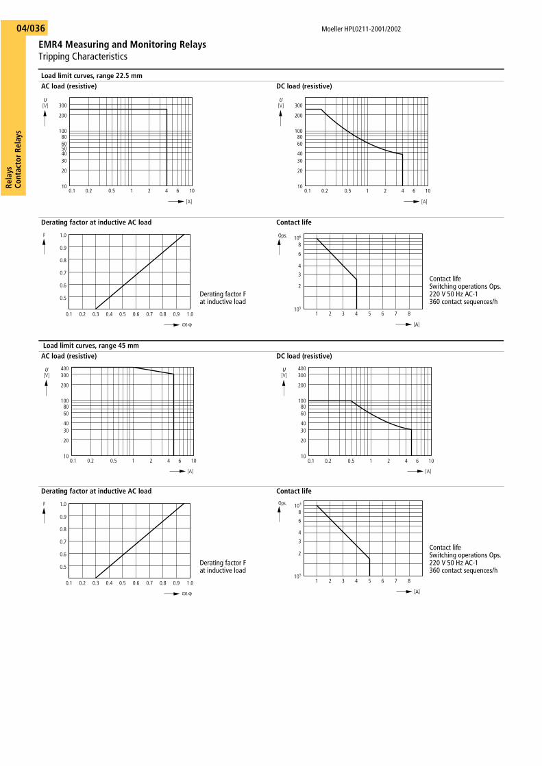
Load limit curves, range 22.5 mmAC load (resistive) DC load (resistive)
Derating factor at inductive AC load Contact life
Derating factor Fat inductive load
Contact lifeSwitching operations Ops.220 V 50 Hz AC-1360 contact sequences/h
Load limit curves, range 45 mm AC load (resistive) DC load (resistive)
Derating factor at inductive AC load Contact life
Derating factor Fat inductive load
Contact lifeSwitching operations Ops.220 V 50 Hz AC-1360 contact sequences/h
300
200
10
20
3040
6050
80100
0.1 0.2 0.5 1 2 4 6 10
[V]U
[A]
300
200
10
20
3040
6080
100
0.1 0.2 0.5 1 2 4 6 10
[A]
[V]U
0.5
0.6
0.7
0.8
0.9
1.0
0.1 0.2 0.3 0.4 0.5 0.6 0.7 0.8 0.9 1.0
cos v
F
[A]
Ops.
2
3
4
6
8
1 2 3 4 5 6 7 8105
106
400300
200
10
20
3040
6080
100
0.1 0.2 0.5 1 2 4 6 10
[A]
[V]U 400
300
200
10
20
3040
6080
100
0.1 0.2 0.5 1 2 4 6 10
[A]
[V]U
0.5
0.6
0.7
0.8
0.9
1.0
0.1 0.2 0.3 0.4 0.5 0.6 0.7 0.8 0.9 1.0
cos v
F
[A]
2
3
4
6
8
1 2 3 4 5 6 7 8105
10 6Ops.
Rela
ysCo
ntac
tor
Rela
ys
Moeller HPL0211-2001/2002
“Easy” Control RelaysTechnical Data
04/037
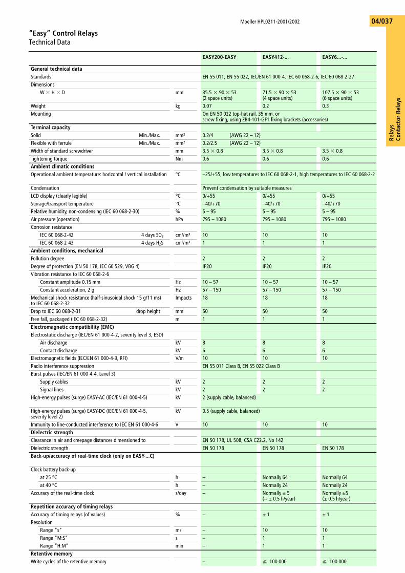
EASY200-EASY EASY412-... EASY6...-...
General technical dataStandards EN 55 011, EN 55 022, IEC/EN 61 000-4, IEC 60 068-2-6, IEC 60 068-2-27Dimensions
W � H � D mm 35.5 � 90 � 53 (2 space units)
71.5 � 90 � 53 (4 space units)
107.5 � 90 � 53 (6 space units)
Weight kg 0.07 0.2 0.3Mounting On EN 50 022 top-hat rail, 35 mm, or
screw fixing, using ZB4-101-GF1 fixing brackets (accessories)Terminal capacitySolid Min./Max. mm² 0.2/4 (AWG 22 – 12)Flexible with ferrule Min./Max. mm² 0.2/2.5 (AWG 22 – 12)Width of standard screwdriver mm 3.5 � 0.8 3.5 � 0.8 3.5 � 0.8Tightening torque Nm 0.6 0.6 0.6Ambient climatic conditionsOperational ambient temperature: horizontal / vertical installation °C –25/+55, low temperatures to IEC 60 068-2-1, high temperatures to IEC 60 068-2-2
Condensation Prevent condensation by suitable measuresLCD display (clearly legible) °C 0/+55 0/+55 0/+55 Storage/transport temperature °C –40/+70 –40/+70 –40/+70Relative humidity, non-condensing (IEC 60 068-2-30) % 5 – 95 5 – 95 5 – 95Air pressure (operation) hPa 795 – 1080 795 – 1080 795 – 1080 Corrosion resistance
IEC 60 068-2-42 4 days SO2 cm³/m³ 10 10 10IEC 60 068-2-43 4 days H2S cm³/m³ 1 1 1
Ambient conditions, mechanicalPollution degree 2 2 2Degree of protection (EN 50 178, IEC 60 529, VBG 4) IP20 IP20 IP20Vibration resistance to IEC 60 068-2-6
Constant amplitude 0.15 mm Hz 10 – 57 10 – 57 10 – 57Constant acceleration, 2 g Hz 57 – 150 57 – 150 57 – 150
Mechanical shock resistance (half-sinusoidal shock 15 g/11 ms)to IEC 60 068-2-32
Impacts 18 18 18
Drop to IEC 60 068-2-31 drop height mm 50 50 50Free fall, packaged (IEC 60 068-2-32) m 1 1 1Electromagnetic compatibility (EMC)Electrostatic discharge (IEC/EN 61 000-4-2, severity level 3, ESD)
Air discharge kV 8 8 8Contact discharge kV 6 6 6
Electromagnetic fields (IEC/EN 61 000-4-3, RFI) V/m 10 10 10Radio interference suppression EN 55 011 Class B, EN 55 022 Class BBurst pulses (IEC/EN 61 000-4-4, Level 3)
Supply cables kV 2 2 2Signal lines kV 2 2 2
High-energy pulses (surge) EASY-AC (IEC/EN 61 000-4-5) kV 2 (supply cable, balanced)
High-energy pulses (surge) EASY-DC (IEC/EN 61 000-4-5, severity level 2)
kV 0.5 (supply cable, balanced)
Immunity to line-conducted interference to IEC EN 61 000-4-6 V 10 10 10Dielectric strengthClearance in air and creepage distances dimensioned to EN 50 178, UL 508, CSA C22.2, No 142Dielectric strength EN 50 178 EN 50 178 EN 50 178Back-up/accuracy of real-time clock (only on EASY-...C)
Clock battery back-upat 25 °C h – Normally 64 Normally 64at 40 °C h – Normally 24 Normally 24
Accuracy of the real-time clock s/day – Normally g 5 (~ g 0.5 h/year)
Normally g5(g 0.5 h/year)
Repetition accuracy of timing relaysAccuracy of timing relays (of values) % – g 1 g 1Resolution
Range “s” ms – 10 10Range “M:S” s – 1 1Range “H:M” min – 1 1
Retentive memoryWrite cycles of the retentive memory – f 100 000 f 100 000
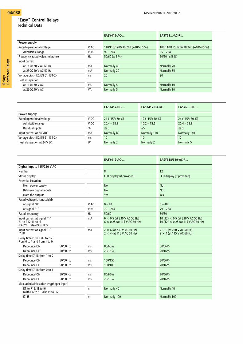
Moeller HPL0211-2001/2002
“Easy” Control RelaysTechnical Data
Rela
ysCo
ntac
tor R
elay
s04/038
EASY412-AC-... EASY61...-AC-R...
Power supplyRated operational voltage V AC 110/115/120/230/240 (+10/–15 %) 100/110/115/120/230/240 (+10/–15 %)
Admissible range V AC 90 – 264 85 – 264Frequency, rated value, tolerance Hz 50/60 (g 5 %) 50/60 (g 5 %)Input current
at 115/120 V AC 60 Hz mA Normally 40 Normally 70at 230/240 V AC 50 Hz mA Normally 20 Normally 35
Voltage dips (IEC/EN 61 131-2) ms 20 20Heat dissipation
at 115/120 V AC VA Normally 5 Normally 10at 230/240 V AC VA Normally 5 Normally 10
EASY412-DC-... EASY412-DA-RC EASY6...-DC-...
Power supplyRated operational voltage V DC 24 (–15/+20 %) 12 (–15/+30 %) 24 (–15/+20 %)
Admissible range V DC 20.4 – 28.8 10.2 – 15.6 20.4 – 28.8Residual ripple % F 5 G5 F 5
Input current at 24 VDC mA Normally 80 Normally 140 Normally 140 Voltage dips (IEC/EN 61 131-2) ms 10 10 10Heat dissipation at 24 V DC W Normally 2 Normally 2 Normally 5
EASY412-AC-... EASY618/619-AC-R...
Digital inputs 115/230 V ACNumber 8 12Status display LCD display (if provided) LCD display (if provided)Potential isolation
From power supply No NoBetween digital inputs No NoFrom the outputs Yes Yes
Rated voltage L (sinusoidal)at signal “0” V AC 0 – 40 0 – 40at signal “1” V AC 79 – 264 79 – 264
Rated frequency Hz 50/60 50/60Input current at signal “1”R1 to R12, I1 to I6 (EASY6... also I9 to I12)
mA 6 x 0.5 (at 230 V AC 50 Hz)6 x 0.25 (at 115 V AC 60 Hz)
10 (12) x 0.5 (at 230 V AC 50 Hz)10 (12) x 0.25 (at 115 V AC 60 Hz)
Input current at signal “1”I7, I8
mA 2 x 6 (at 230 V AC 50 Hz)2 x 4 (at 115 V AC 60 Hz)
2 x 6 (at 230 V AC 50 Hz)2 x 4 (at 115 V AC 60 Hz)
Delay time I1 to I6/I9 to I12From 0 to 1 and from 1 to 0
Debounce ON 50/60 Hz ms 80/66n 80/66nDebounce OFF 50/60 Hz ms 20/16n 20/16n
Delay time I7, I8 from 1 to 0Debounce ON 50/60 Hz ms 160/150 80/66nDebounce OFF 50/60 Hz ms 100/100 20/16n
Delay time I7, I8 from 0 to 1 Debounce ON 50/60 Hz ms 80/66n 80/66nDebounce OFF 50/60 Hz ms 20/16n 20/16n
Max. admissible cable length (per input)R1 to R12, I1 to I6 (with EASY 6... also I9 to I12)
m Normally 40 Normally 40
I7, I8 m Normally 100 Normally 100
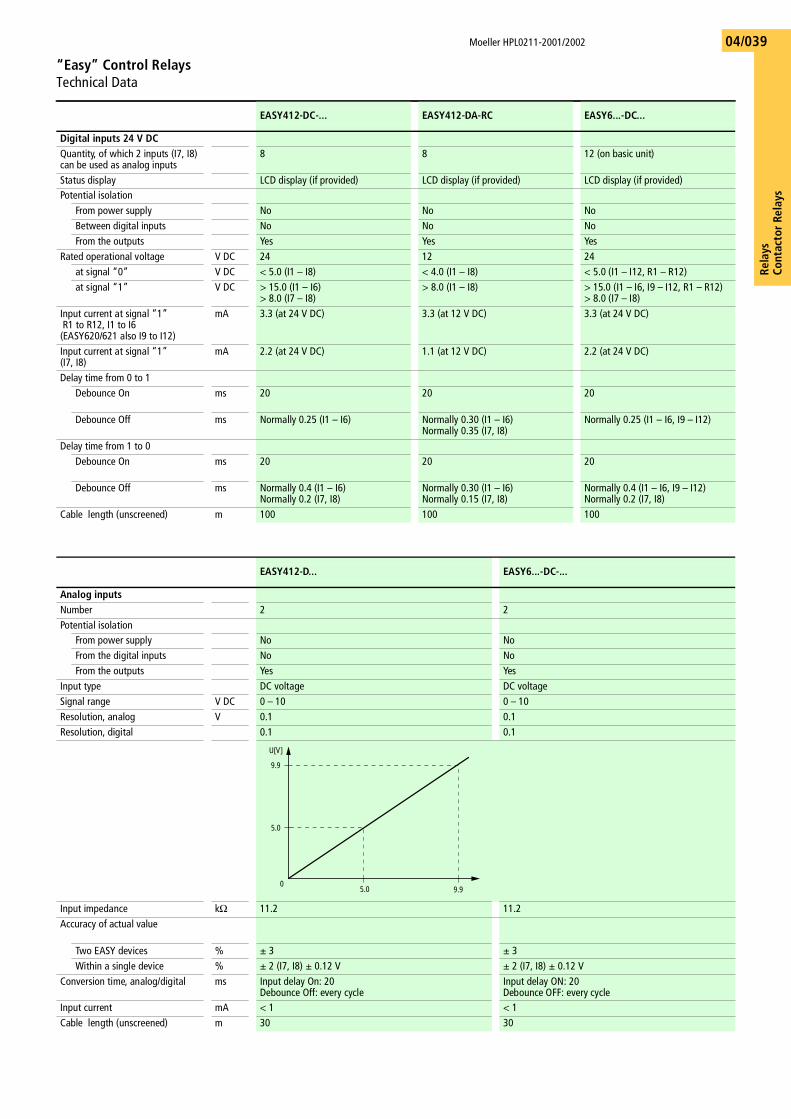
Rela
ysCo
ntac
tor
Rela
ys
Moeller HPL0211-2001/2002
“Easy” Control RelaysTechnical Data
04/039
EASY412-DC-... EASY412-DA-RC EASY6...-DC...
Digital inputs 24 V DCQuantity, of which 2 inputs (I7, I8) can be used as analog inputs
8 8 12 (on basic unit)
Status display LCD display (if provided) LCD display (if provided) LCD display (if provided)Potential isolation
From power supply No No NoBetween digital inputs No No NoFrom the outputs Yes Yes Yes
Rated operational voltage V DC 24 12 24at signal “0” V DC < 5.0 (I1 – I8) < 4.0 (I1 – I8) < 5.0 (I1 – I12, R1 – R12)at signal “1” V DC > 15.0 (I1 – I6)
> 8.0 (I7 – I8)> 8.0 (I1 – I8) > 15.0 (I1 – I6, I9 – I12, R1 – R12)
> 8.0 (I7 – I8)Input current at signal “1” R1 to R12, I1 to I6(EASY620/621 also I9 to I12)
mA 3.3 (at 24 V DC) 3.3 (at 12 V DC) 3.3 (at 24 V DC)
Input current at signal “1” (I7, I8)
mA 2.2 (at 24 V DC) 1.1 (at 12 V DC) 2.2 (at 24 V DC)
Delay time from 0 to 1Debounce On ms 20 20 20
Debounce Off ms Normally 0.25 (I1 – I6) Normally 0.30 (I1 – I6)Normally 0.35 (I7, I8)
Normally 0.25 (I1 – I6, I9 – I12)
Delay time from 1 to 0Debounce On ms 20 20 20
Debounce Off ms Normally 0.4 (I1 – I6)Normally 0.2 (I7, I8)
Normally 0.30 (I1 – I6)Normally 0.15 (I7, I8)
Normally 0.4 (I1 – I6, I9 – I12)Normally 0.2 (I7, I8)
Cable length (unscreened) m 100 100 100
EASY412-D... EASY6...-DC-...
Analog inputsNumber 2 2Potential isolation
From power supply No NoFrom the digital inputs No NoFrom the outputs Yes Yes
Input type DC voltage DC voltageSignal range V DC 0 – 10 0 – 10Resolution, analog V 0.1 0.1Resolution, digital 0.1 0.1
Input impedance kO 11.2 11.2Accuracy of actual value
Two EASY devices % g 3 g 3Within a single device % g 2 (I7, I8) g 0.12 V g 2 (I7, I8) g 0.12 V
Conversion time, analog/digital ms Input delay On: 20 Debounce Off: every cycle
Input delay ON: 20 Debounce OFF: every cycle
Input current mA < 1 < 1 Cable length (unscreened) m 30 30
U[V]
5.0
9.9
5.0 9.90
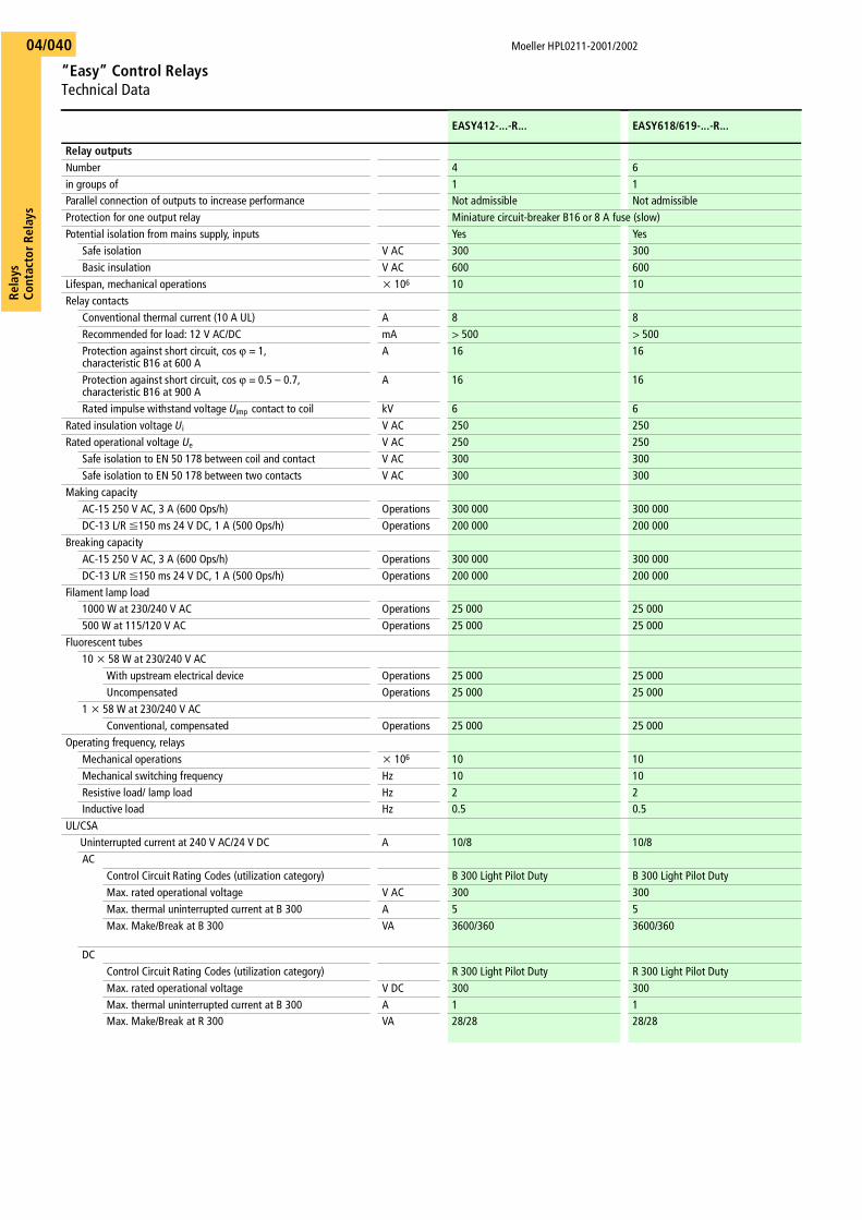
Moeller HPL0211-2001/2002
“Easy” Control RelaysTechnical Data
Rela
ysCo
ntac
tor R
elay
s04/040
EASY412-...-R... EASY618/619-...-R...
Relay outputsNumber 4 6in groups of 1 1Parallel connection of outputs to increase performance Not admissible Not admissibleProtection for one output relay Miniature circuit-breaker B16 or 8 A fuse (slow)Potential isolation from mains supply, inputs Yes Yes
Safe isolation V AC 300 300Basic insulation V AC 600 600
Lifespan, mechanical operations x 106 10 10Relay contacts
Conventional thermal current (10 A UL) A 8 8Recommended for load: 12 V AC/DC mA > 500 > 500Protection against short circuit, cos v = 1, characteristic B16 at 600 A
A 16 16
Protection against short circuit, cos v = 0.5 – 0.7, characteristic B16 at 900 A
A 16 16
Rated impulse withstand voltage Uimp contact to coil kV 6 6Rated insulation voltage Ui V AC 250 250Rated operational voltage Ue V AC 250 250
Safe isolation to EN 50 178 between coil and contact V AC 300 300Safe isolation to EN 50 178 between two contacts V AC 300 300
Making capacityAC-15 250 V AC, 3 A (600 Ops/h) Operations 300 000 300 000 DC-13 L/R F150 ms 24 V DC, 1 A (500 Ops/h) Operations 200 000 200 000
Breaking capacityAC-15 250 V AC, 3 A (600 Ops/h) Operations 300 000 300 000 DC-13 L/R F150 ms 24 V DC, 1 A (500 Ops/h) Operations 200 000 200 000
Filament lamp load1000 W at 230/240 V AC Operations 25 000 25 000 500 W at 115/120 V AC Operations 25 000 25 000
Fluorescent tubes 10 x 58 W at 230/240 V AC
With upstream electrical device Operations 25 000 25 000 Uncompensated Operations 25 000 25 000
1 x 58 W at 230/240 V ACConventional, compensated Operations 25 000 25 000
Operating frequency, relaysMechanical operations x 106 10 10Mechanical switching frequency Hz 10 10Resistive load/ lamp load Hz 2 2Inductive load Hz 0.5 0.5
UL/CSAUninterrupted current at 240 V AC/24 V DC A 10/8 10/8AC
Control Circuit Rating Codes (utilization category) B 300 Light Pilot Duty B 300 Light Pilot DutyMax. rated operational voltage V AC 300 300Max. thermal uninterrupted current at B 300 A 5 5Max. Make/Break at B 300 VA 3600/360 3600/360
DCControl Circuit Rating Codes (utilization category) R 300 Light Pilot Duty R 300 Light Pilot DutyMax. rated operational voltage V DC 300 300Max. thermal uninterrupted current at B 300 A 1 1Max. Make/Break at R 300 VA 28/28 28/28
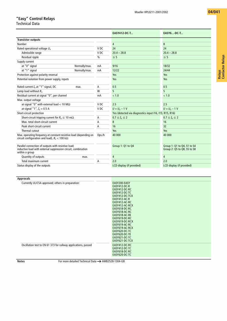
Rela
ysCo
ntac
tor
Rela
ys
Moeller HPL0211-2001/2002
“Easy” Control RelaysTechnical Data
04/041
EASY412-DC-T... EASY6...-DC-T...
Transistor outputsNumber 4 8Rated operational voltage Ue V DC 24 24
Admissible range V DC 20.4 – 28.8 20.4 – 28.8Residual ripple % F 5 F 5
Supply currentat “0” signal Normally/max. mA 9/16 18/32 at “1” signal Normally/max. mA 12/22 24/44
Protection against polarity reversal Yes YesPotential isolation from power supply, inputs Yes Yes
Rated current Ie at “1” signal, DC max. A 0.5 0.5Lamp load without Rv W 5 5Residual current at signal “0”, per channel mA < 1.0 < 1.0Max. output voltage
at signal “0” with external load < 10 MO V DC 2.5 2.5at signal “1”, Ie = 0.5 A V DC U = Ue – 1 V U = Ue – 1 V
Short-circuit protection Yes (detected via diagnostics input I16, I15; R15, R16)Short-circuit tripping current for Ra F 10 mO A 0.7 F Ie F 2 0.7 F Ie F 2Max. total short-circuit current A 8 16Peak short-circuit current A 16 32Thermal cutout Yes Yes
Max. operating frequency at constant resistive load (depending on circuit configuration and load), RL < 100 kO
Ops./h 40 000 40 000
Parallel connection of outputs with resistive load;inductive load with external suppression circuit, combination within a group
Group 1: Q1 to Q4 Group 1: Q1 to Q4, S1 to S4Group 2: Q5 to Q8, S5 to S8
Quantity of outputs max. 4 4Total maximum current A 2.0 2.0
Status display of the outputs LCD display (if provided) LCD display (if provided)
ApprovalsCurrently UL/CSA approved; others in preparation: EASY200-EASY
EASY412-DC-REASY412-DC-RCEASY412-DC-TCEASY412-DC-TCXEASY412-AC-REASY412-AC-RCEASY412-AC-RCXEASY618-DC-RCEASY618-AC-RCEASY618-AC-REEASY619-DC-RCEASY619-DC-RCXEASY619-AC-RCEASY619-AC-RCXEASY620-DC-TCEASY620-DC-TEEASY621-DC-TCEASY621-DC-TCX
Oscillation test to EN 61 373 for railway applications, passed EASY412-DC-RCEASY412-DC-TCEASY618-DC-RCEASY620-DC-TC
Notes For more detailed Technical Data a AWB2528-1304-GB
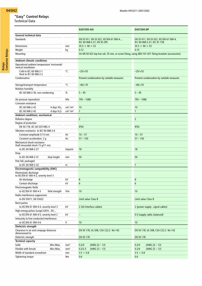
Moeller HPL0211-2001/2002
“Easy” Control RelaysTechnical Data
Rela
ysCo
ntac
tor R
elay
s04/042
EASY205-ASI EASY204-DP
General technical dataStandards EN 55 011, EN 55 022, IEC/EN 61 000-4...,
IEC 60 068-2-27, EN 50 295EN 55 011, EN 55 022, IEC/EN 61 000-4, IEC 60 068-2-27, IEC 61 158
Dimensions mm 35.5 x 90 x 53 35.5 x 90 x 53Weight kg 0.12 0.15Mounting On EN 50 022 top-hat rail, 35 mm, or screw fixing, using ZB4-101-GF1 fixing brackets (accessories)
Ambient climatic conditionsOperational ambient temperature: horizontal/vertical installation
Cold to IEC 60 068-2-1Heat to IEC 60 068-2-2
°C –25/+55 –25/+55
Condensation Prevent condensation by suitable measures Prevent condensation by suitable measures
Storage/transport temperature °C –40/+70 –40/+70Relative humidity
IEC 60 068-2-30, non-condensing % 5 – 95 5 – 95
Air pressure (operation) hPa 795 – 1080 795 – 1080Corrosion resistance
IEC 60 068-2-42 4 days SO2 cm3 /m3 10 10IEC 60 068-2-43 4 days H2S cm3 /m3 1 1
Ambient conditions, mechanicalPollution degree 2 2Degree of protection
EN 50 178, IEC 60 529 VBG 4 IP20 IP20Vibration resistance to IEC 60 068-2-6
Constant amplitude 0.15 mm Hz 10 – 57 10 – 57Constant acceleration, 2 g Hz 57 – 150 57 – 150
Mechanical shock resistance (half-sinusoidal shock 15 g/11 ms)
to IEC 60 068-2-27 Impacts 18 18Drop
to IEC 60 068-2-31 drop height mm 50 50Free fall, packaged
to IEC 60 068-2-32 m 1 1Electromagnetic compatibility (EMC)Electrostatic dischargeto IEC/EN 61 000-4-2, severity level 3
Air discharge kV 8 8Contact discharge kV 6 6
Electromagnetic fieldsto IEC/EN 61 000-4-3 field strength V/m 10 10
Radio interference suppressionto EN 55011, EN 55022 Limit value Class B Limit value Class B
Burst pulsesto IEC/EN 61 000-4-4, severity level 3 kV 2 (AS-Interface cables) 2 (power supply-, signal cables)
High-energy pulses (surge) EASY...-DC...to IEC/EN 61 000-4-5, severity level 2 kV – 0.5 (supply cable, balanced)
Immunity to line-conducted interferenceto IEC/EN 61 000-4-6 V 10 10
Dielectric strengthClearance in air and creepage distances dimensioned to
EN 50 178, UL 508, CSA C22.2 No 142 EN 50 178, UL 508, CSA C22.2 No 142
Dielectric strength EN 50 178 EN 50 178Terminal capacitySolid Min./Max. mm² 0.2/4 (AWG 22 – 12) 0.2/4 (AWG 22 – 12)Flexible with ferrule Min./Max. mm² 0.2/2.5 (AWG 22 – 12) 0.2/4 (AWG 22 – 12)Width of standard screwdriver mm 3.5 � 0.8 3.5 � 0.8Tightening torque Nm 0.6 0.6
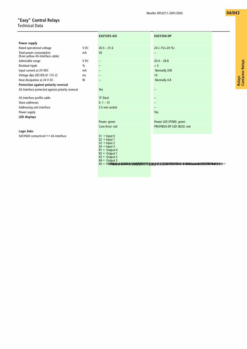
Rela
ysCo
ntac
tor
Rela
ys
Moeller HPL0211-2001/2002
“Easy” Control RelaysTechnical Data
04/043
EASY205-ASI EASY204-DP
Power supplyRated operational voltage V DC 26.5 – 31.6 24 (–15/+20 %)Total power consumption (from yellow AS-Interface cable)
mA 30 –
Admissible range V DC – 20.4 – 28.8Residual ripple % – < 5Input current at 24 VDC mA – Normally 200 Voltage dips (IEC/EN 61 131-2) ms – 10Heat dissipation at 24 V DC W – Normally 4.8 Protection against polarity reversalAS-Interface protected against polarity reversal Yes –
AS-Interface profile cable 7F (hex) –Slave addresses 0. 1 – 31 –Addressing unit interface 3.5 mm socket –Power supply YesLED displays
Power: green Power LED (POW): greenCom-Error: red PROFIBUS-DP LED (BUS): red
Logic linksEASY600 contact/coil t AS-Interface S1 l Input 0
S2 l Input 1S3 l Input 2S4 l Input 3R1 m Output 0 R2 m Output 1R3 m Output 2R4 m Output 3R5 m PARAp-0..0244 Tc(m)Tj/F(t)47.7.9(gic)12.8( l)28.06 TD-818 -1.tROUscn24.06 TD-PD0 1um PARAp-0..0244 Tc(m)Tj/F(t)47.7.9(gic)12.8( l)28.06 TD-818 -1.tROUscn24.06 TD-PD0 1um PARAp-0..0244 Tc(m)Tj/F(t)47.7.9(gic)12.8( l)28.06 TD-818 -1.tROUscn24.06 TD-PD0 1um
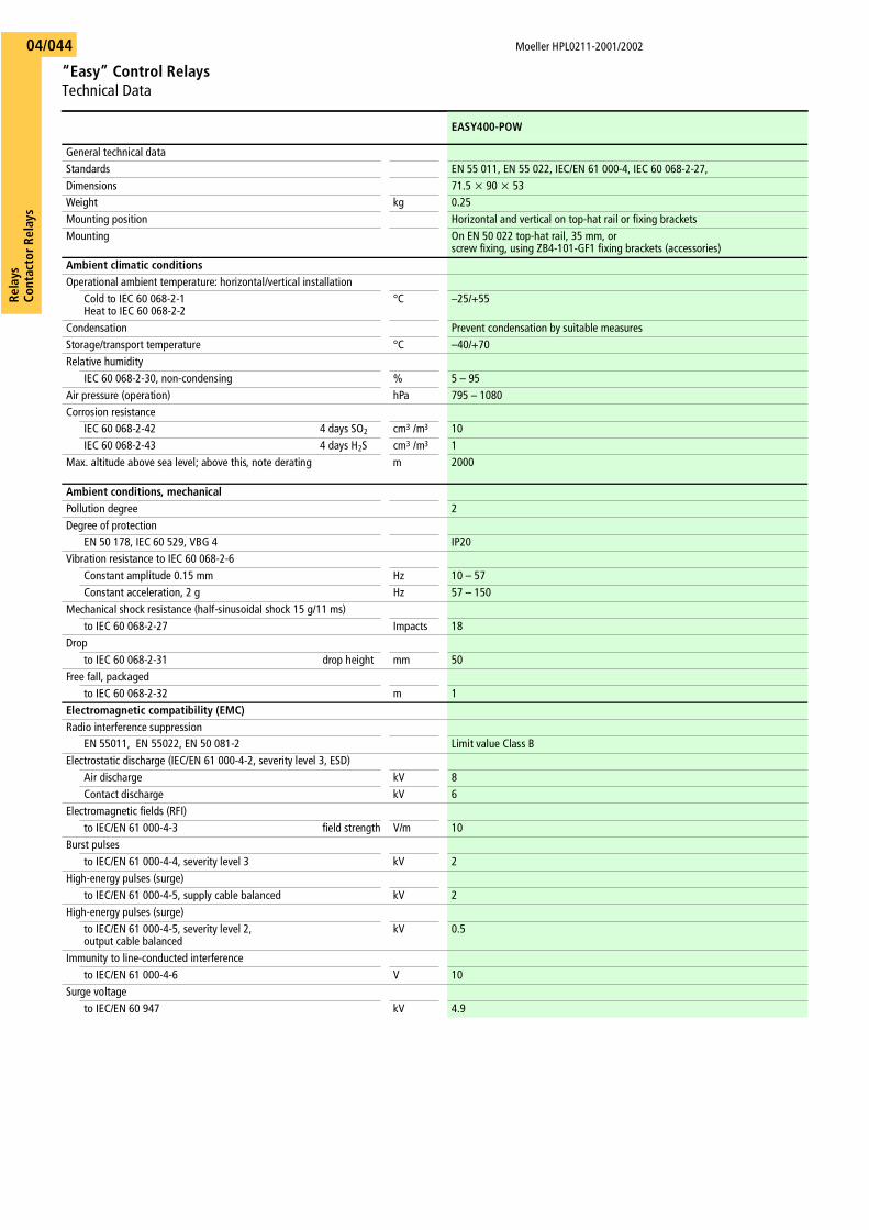
Moeller HPL0211-2001/2002
“Easy” Control RelaysTechnical Data
Rela
ysCo
ntac
tor R
elay
s04/044
EASY400-POW
General technical dataStandards EN 55 011, EN 55 022, IEC/EN 61 000-4, IEC 60 068-2-27, Dimensions 71.5 x 90 x 53Weight kg 0.25Mounting position Horizontal and vertical on top-hat rail or fixing bracketsMounting On EN 50 022 top-hat rail, 35 mm, or
screw fixing, using ZB4-101-GF1 fixing brackets (accessories)Ambient climatic conditionsOperational ambient temperature: horizontal/vertical installation
Cold to IEC 60 068-2-1Heat to IEC 60 068-2-2
°C –25/+55
Condensation Prevent condensation by suitable measuresStorage/transport temperature °C –40/+70Relative humidity
IEC 60 068-2-30, non-condensing % 5 – 95Air pressure (operation) hPa 795 – 1080 Corrosion resistance
IEC 60 068-2-42 4 days SO2 cm3 /m3 10IEC 60 068-2-43 4 days H2S cm3 /m3 1
Max. altitude above sea level; above this, note derating m 2000
Ambient conditions, mechanicalPollution degree 2Degree of protection
EN 50 178, IEC 60 529, VBG 4 IP20Vibration resistance to IEC 60 068-2-6
Constant amplitude 0.15 mm Hz 10 – 57Constant acceleration, 2 g Hz 57 – 150
Mechanical shock resistance (half-sinusoidal shock 15 g/11 ms)to IEC 60 068-2-27 Impacts 18
Dropto IEC 60 068-2-31 drop height mm 50
Free fall, packagedto IEC 60 068-2-32 m 1
Electromagnetic compatibility (EMC)Radio interference suppression
EN 55011, EN 55022, EN 50 081-2 Limit value Class BElectrostatic discharge (IEC/EN 61 000-4-2, severity level 3, ESD)
Air discharge kV 8Contact discharge kV 6
Electromagnetic fields (RFI)to IEC/EN 61 000-4-3 field strength V/m 10
Burst pulsesto IEC/EN 61 000-4-4, severity level 3 kV 2
High-energy pulses (surge) to IEC/EN 61 000-4-5, supply cable balanced kV 2
High-energy pulses (surge)to IEC/EN 61 000-4-5, severity level 2, output cable balanced
kV 0.5
Immunity to line-conducted interferenceto IEC/EN 61 000-4-6 V 10
Surge voltageto IEC/EN 60 947 kV 4.9
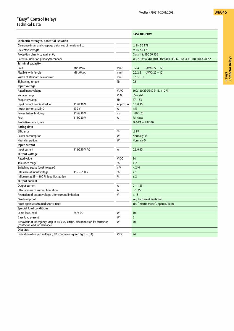
Rela
ysCo
ntac
tor
Rela
ys
Moeller HPL0211-2001/2002
“Easy” Control RelaysTechnical Data
04/045
EASY400-POW
Dielectric strength, potential isolationClearance in air and creepage distances dimensioned to to EN 50 178Dielectric strength to EN 50 178Protection class Uout against Uin Class II to IEC 60 536Potential isolation primary/secondary Yes, SELV to VDE 0100 Part 410, IEC 60 364-4-41, HD 384.4.41 S2Terminal capacitySolid Min./Max. mm² 0.2/4 (AWG 22 – 12)Flexible with ferrule Min./Max. mm² 0.2/2.5 (AWG 22 – 12)Width of standard screwdriver mm 3.5 � 0.8Tightening torque Nm 0.6Input voltageRated input voltage V AC 100/120/230/240 (–15/+10 %)Voltage range V AC 85 – 264 Frequency range Hz 47 – 63 Input current nominal value 115/230 V Approx. A 0.3/0.15Inrush current at 25°C 230 V A < 5Power failure bridging 115/230 V ms >10/>20 Fuse 115/230 V A 2/1 slowProtective switch, min. FAZ-C1 or FAZ-B6Rating dataEfficiency % F 87 Power consumption W Normally 35 Heat dissipation W Normally 5 Input currentInput current 115/230 V AC A 0.3/0.15Output voltageRated value V DC 24Tolerance range % g 2 Switching peaks (peak to peak) mV < 240Influence of input voltage 115 – 230 V % g 1 Influence at 25 – 100 % load fluctuation % g 2 Output currentOutput current A 0 – 1.25Effectiveness of current limitation A > 1.25Reduction of output voltage after current limitation V < 18Overload proof Yes, by current limitationProof against sustained short circuit Yes, “hiccup mode”, approx. 10 Hz Special load conditionsLamp load, cold 24 V DC W 10Base load present W 5Behaviour at Emergency-Stop in 24 V DC circuit, disconnection by contactor(contactor load, no damage)
W 30
DisplaysIndication of output voltage (LED, continuous green light = OK) V DC 24
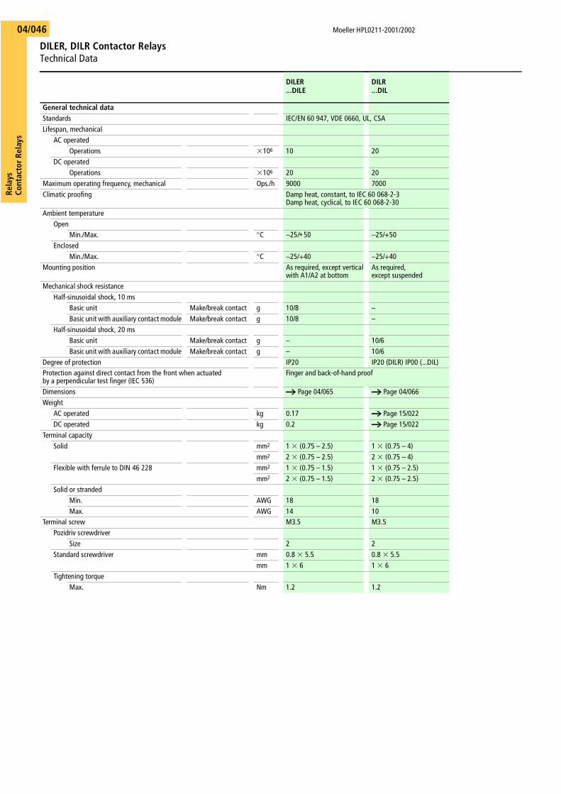
Moeller HPL0211-2001/2002
DILER, DILR Contactor RelaysTechnical Data
Rela
ysCo
ntac
tor R
elay
s04/046
DILER...DILE
DILR...DIL
General technical dataStandards IEC/EN 60 947, VDE 0660, UL, CSALifespan, mechanical
AC operatedOperations �106 10 20
DC operatedOperations �106 20 20
Maximum operating frequency, mechanical Ops./h 9000 7000Climatic proofing Damp heat, constant, to IEC 60 068-2-3
Damp heat, cyclical, to IEC 60 068-2-30Ambient temperature
OpenMin./Max. °C −25/+50 −25/+50
EnclosedMin./Max. °C −25/+40 −25/+40
Mounting position As required, except verticalwith A1/A2 at bottom
As required,except suspended
Mechanical shock resistanceHalf-sinusoidal shock, 10 ms
Basic unit Make/break contact g 10/8 –Basic unit with auxiliary contact module Make/break contact g 10/8 –
Half-sinusoidal shock, 20 msBasic unit Make/break contact g – 10/6Basic unit with auxiliary contact module Make/break contact g – 10/6
Degree of protection IP20 IP20 (DILR) IP00 (...DIL)Protection against direct contact from the front when actuatedby a perpendicular test finger (IEC 536)
Finger and back-of-hand proof
Dimensions a Page 04/065 a Page 04/066Weight
AC operated kg 0.17 a Page 15/022DC operated kg 0.2 a Page 15/022
Terminal capacitySolid mm2 1 � (0.75 – 2.5) 1 � (0.75 – 4)
mm2 2 � (0.75 – 2.5) 2 � (0.75 – 4)Flexible with ferrule to DIN 46 228 mm2 1 � (0.75 – 1.5) 1 � (0.75 – 2.5)
mm2 2 � (0.75 – 1.5) 2 � (0.75 – 2.5)Solid or stranded
Min. AWG 18 18Max. AWG 14 10
Terminal screw M3.5 M3.5Pozidriv screwdriver
Size 2 2Standard screwdriver mm 0.8 � 5.5 0.8 � 5.5
mm 1 � 6 1 � 6Tightening torque
Max. Nm 1.2 1.2
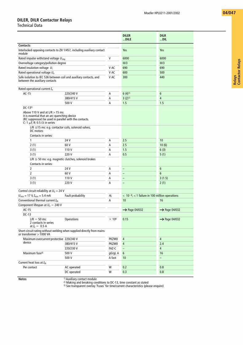
Rela
ysCo
ntac
tor
Rela
ys
Moeller HPL0211-2001/2002
DILER, DILR Contactor RelaysTechnical Data
04/047
DILER...DILE
DILR...DIL
ContactsInterlocked opposing contacts to ZH 1/457, including auxiliary contact module
Yes Yes
Rated impulse withstand voltage Uimp V 6000 6000Overvoltage category/pollution degree III/3 III/3Rated insulation voltage Ui V AC 690 690Rated operational voltage Ue V AC 600 500Safe isolation to IEC 536 between coil and auxiliary contacts, and between the auxiliary contacts
V AC 300 440
Rated operational current IeAC-15 220/240 V A 6 (4)1) 6
380/415 V A 3 (2)1) 4500 V A 1.5 1.5
DC-132)
Above 110 V and at L/R > 15 ms:it is essential that an arc-quenching device (RC suppressor) be used in parallel with the contacts.C: 1 �F, R: 0.5 � in series
L/R �15 ms: e.g. contactor coils, solenoid valves, DC motorsContacts in series:1 24 V A 2.5 102 (1) 60 V A 2.5 10 (6)3 (1) 110 V A 1.5 6 (3)3 (1) 220 V A 0.5 5 (1)L/R � 50 ms: e.g. magnetic clutches, solenoid brakesContacts in series:2 24 V A – 62 60 V A – 63 (1) 110 V A – 3 (1.5)3 (1) 220 V A – 2 (1)
Control circuit reliability at Ue = 24 VUmin = 17 V, Imin = 5.4 mA Fault probability HF < 10�8, < 1 failure in 100 million operationsConventional thermal current Ith A 10 16Component lifespan at Ue � 240 V
AC-15 a Page 04/032 a Page 04/032DC-13
L/R � 50 ms: 2 contacts in seriesat Ie � 0.5 A
Operations � 106 0.15 a Page 04/032
Short-circuit rating without welding when supplied directly from mains or transformer > 1000 VA
Maximum overcurrent protective device
220/240 V PKZM0 4 4380/415 V PKZM0 4 2.4220/230 V FAZ-C – 4
Maximum fuse3) 500 V gG/gL A 6 16500 V A fast 10 –
Current heat loss at IthPer contact AC operated W 0.2 0.8
DC operated W 0.3 0.8
Notes 1) Auxiliary contact module2) Making and breaking conditions to DC-13, time constant as stated3) See transparent overlay ‘Fuses’ for time/current characteristics (please enquire)
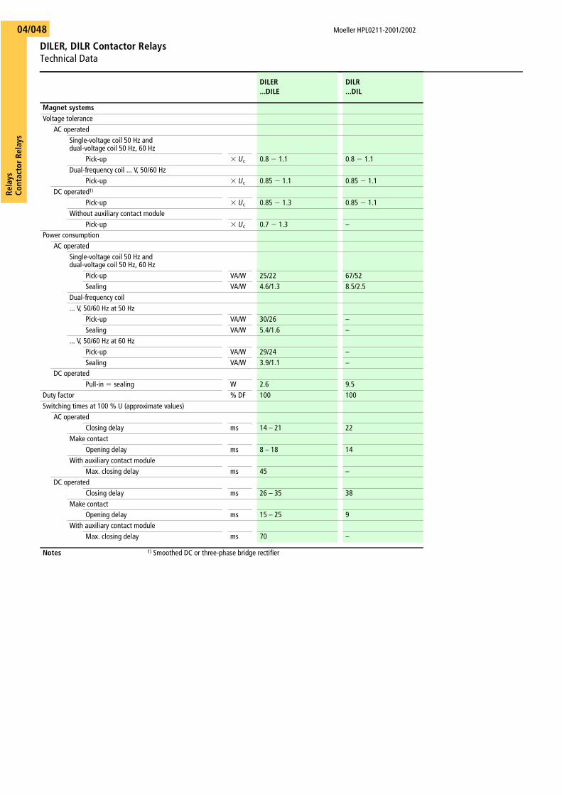
Moeller HPL0211-2001/2002
DILER, DILR Contactor RelaysTechnical Data
Rela
ysCo
ntac
tor R
elay
s04/048
DILER...DILE
DILR...DIL
Magnet systemsVoltage tolerance
AC operatedSingle-voltage coil 50 Hz anddual-voltage coil 50 Hz, 60 Hz
Pick-up � Uc 0.8 � 1.1 0.8 � 1.1Dual-frequency coil ... V, 50/60 Hz
Pick-up � Uc 0.85 � 1.1 0.85 � 1.1DC operated1)
Pick-up � Uc 0.85 � 1.3 0.85 � 1.1Without auxiliary contact module
Pick-up � Uc 0.7 � 1.3 –Power consumption
AC operatedSingle-voltage coil 50 Hz anddual-voltage coil 50 Hz, 60 Hz
Pick-up VA/W 25/22 67/52Sealing VA/W 4.6/1.3 8.5/2.5
Dual-frequency coil... V, 50/60 Hz at 50 Hz
Pick-up VA/W 30/26 –Sealing VA/W 5.4/1.6 –
... V, 50/60 Hz at 60 HzPick-up VA/W 29/24 –Sealing VA/W 3.9/1.1 –
DC operatedPull-in � sealing W 2.6 9.5
Duty factor % DF 100 100Switching times at 100 % U (approximate values)
AC operatedClosing delay ms 14 – 21 22
Make contactOpening delay ms 8 – 18 14
With auxiliary contact moduleMax. closing delay ms 45 –
DC operatedClosing delay ms 26 – 35 38
Make contactOpening delay ms 15 – 25 9
With auxiliary contact moduleMax. closing delay ms 70 –
Notes 1) Smoothed DC or three-phase bridge rectifier
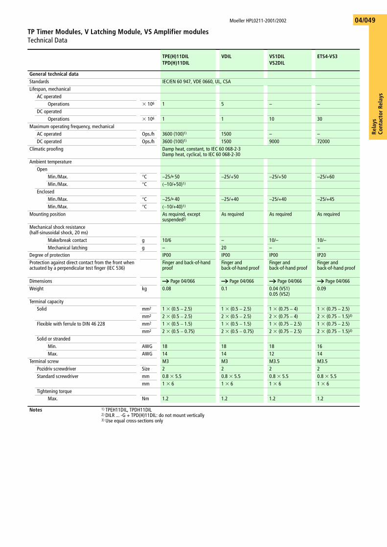
Rela
ysCo
ntac
tor
Rela
ys
Moeller HPL0211-2001/2002
TP Timer Modules, V Latching Module, VS Amplifier modulesTechnical Data
04/049
TPE(H)11DILTPD(H)11DIL
VDIL VS1DILVS2DIL
ETS4-VS3
General technical dataStandards IEC/EN 60 947, VDE 0660, UL, CSALifespan, mechanical
AC operatedOperations � 106 1 5 – –
DC operatedOperations � 106 1 1 10 30
Maximum operating frequency, mechanicalAC operated Ops./h 3600 (100)1) 1500 – –DC operated Ops./h 3600 (100)1) 1500 9000 72000
Climatic proofing Damp heat, constant, to IEC 60 068-2-3Damp heat, cyclical, to IEC 60 068-2-30
Ambient temperatureOpen
Min./Max. °C −25/+50 −25/+50 −25/+50 −25/+60Min./Max. °C (−10/+50)1)
EnclosedMin./Max. °C −25/+40 −25/+40 −25/+40 −25/+45Min./Max. °C (−10/+40)1)
Mounting position As required, except suspended2)
As required As required As required
Mechanical shock resistance (half-sinusoidal shock, 20 ms)
Make/break contact g 10/6 – 10/– 10/–Mechanical latching g – 20 – –
Degree of protection IP00 IP00 IP00 IP20Protection against direct contact from the front when actuated by a perpendicular test finger (IEC 536)
Finger and back-of-hand proof
Finger and back-of-hand proof
Finger and back-of-hand proof
Finger and back-of-hand proof
Dimensions a Page 04/066 a Page 04/066 a Page 04/066 a Page 04/066Weight kg 0.08 0.1 0.04 (VS1)
0.05 (VS2)0.09
Terminal capacitySolid mm2 1 � (0.5 – 2.5) 1 � (0.5 – 2.5) 1 � (0.75 – 4) 1 � (0.75 – 2.5)
mm2 2 � (0.5 – 2.5) 2 � (0.5 – 2.5) 2 � (0.75 – 4) 2 � (0.75 – 1.5)3)
Flexible with ferrule to DIN 46 228 mm2 1 � (0.5 – 1.5) 1 � (0.5 – 1.5) 1 � (0.75 – 2.5) 1 � (0.75 – 2.5)mm2 2 � (0.5 – 0.75) 2 � (0.5 – 0.75) 2 � (0.75 – 2.5) 2 � (0.75 – 1.5)3)
Solid or strandedMin. AWG 18 18 18 16Max. AWG 14 14 12 14
Terminal screw M3 M3 M3.5 M3.5Pozidriv screwdriver Size 2 2 2 2Standard screwdriver mm 0.8 � 5.5 0.8 � 5.5 0.8 � 5.5 0.8 � 5.5
mm 1 � 6 1 � 6 1 � 6 1 � 6Tightening torque
Max. Nm 1.2 1.2 1.2 1.2
Notes 1) TPEH11DIL, TPDH11DIL2) DILR ... -G + TPD(H)11DIL: do not mount vertically3) Use equal cross-sections only
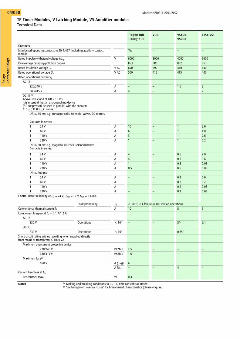
Moeller HPL0211-2001/2002
TP Timer Modules, V Latching Module, VS Amplifier modulesTechnical Data
Rela
ysCo
ntac
tor R
elay
s04/050
TPE(H)11DILTPD(H)11DIL
VDIL VS1DILVS2DIL
ETS4-VS3
ContactsInterlocked opposing contacts to ZH 1/457, including auxiliary contact module
Yes – – –
Rated impulse withstand voltage Uimp V 6000 8000 4000 6000Overvoltage category/pollution degree III/3 III/3 III/2 III/3Rated insulation voltage Ui V AC 690 690 440 440Rated operational voltage Ue V AC 500 415 415 440Rated operational current Ie
AC-15220/240 V A 4 – 1.5 2380/415 V A 4 – 1 2
DC-13 1)
Above 110 V and at L/R > 15 ms:it is essential that an arc-quenching device (RC suppressor) be used in parallel with the contacts.C: 1 �F, R: 0.5 ς in series
L/R � 15 ms: e.g. contactor coils, solenoid valves, DC motors
Contacts in series:1 24 V A 10 – 1 2.61 60 V A 6 – 1 1.01 110 V A 3 – 1 0.61 220 V A 1 – 1 0.2L/R � 50 ms: e.g. magnetic clutches, solenoid brakesContacts in series:
1 24 V A 4 – 0.5 2.01 60 V A 4 – 0.5 0.61 110 V A 1 – 0.5 0.081 220 V A 0.5 0.5 0.08L/R � 300 ms1 24 V A – – 0.2 0.61 60 V A – – 0.2 0.21 110 V A – – 0.2 0.081 220 V A – – 0.2 0.03
Control circuit reliability at Ue = 24 V, Umin = 17 V, Imin = 5.4 mA
Fault probability HF < 10�8, < 1 failure in 100 million operationsConventional thermal current Ith A 10 – 8 6Component lifespan at Ie � 0.1 A/1.2 A
AC-15230 V Operations � 106 – – 8/– 7/1
DC-13230 V Operations � 106 – – 0.85/– –
Short-circuit rating without welding when supplied directly from mains or transformer > 1000 VA
Maximum overcurrent protective device220/240 V PKZM0 2.5 – – –380/415 V PKZM0 1.6 – – –
Maximum fuse2)
500 V A gG/gL 6 – – –A fast – – 4 4
Current heat loss at IthPer contact, max. W 0.3 – – –���������������������������������������������������������������������������������������������������������������������������������������������������������������������������������������������������������������������������������������������������������������������������
���������������������������������������������������������������������������������������������������������������������������������������������������������������������������������������������������������������������������������������������������������������������������������������������������������������������������������������������������������������������������������������������������������������������������������������������������������������������������������������������������������������������������������������������������������������������������������������������������������������������������������������������������������������������������������������������������������������������������������������������������������������������������������������������������������������������������������
Notes 1) Making and breaking conditions to DC-13, time constant as stated2) See transparent overlay 'Fuses' for time/current characteristics (please enquire)
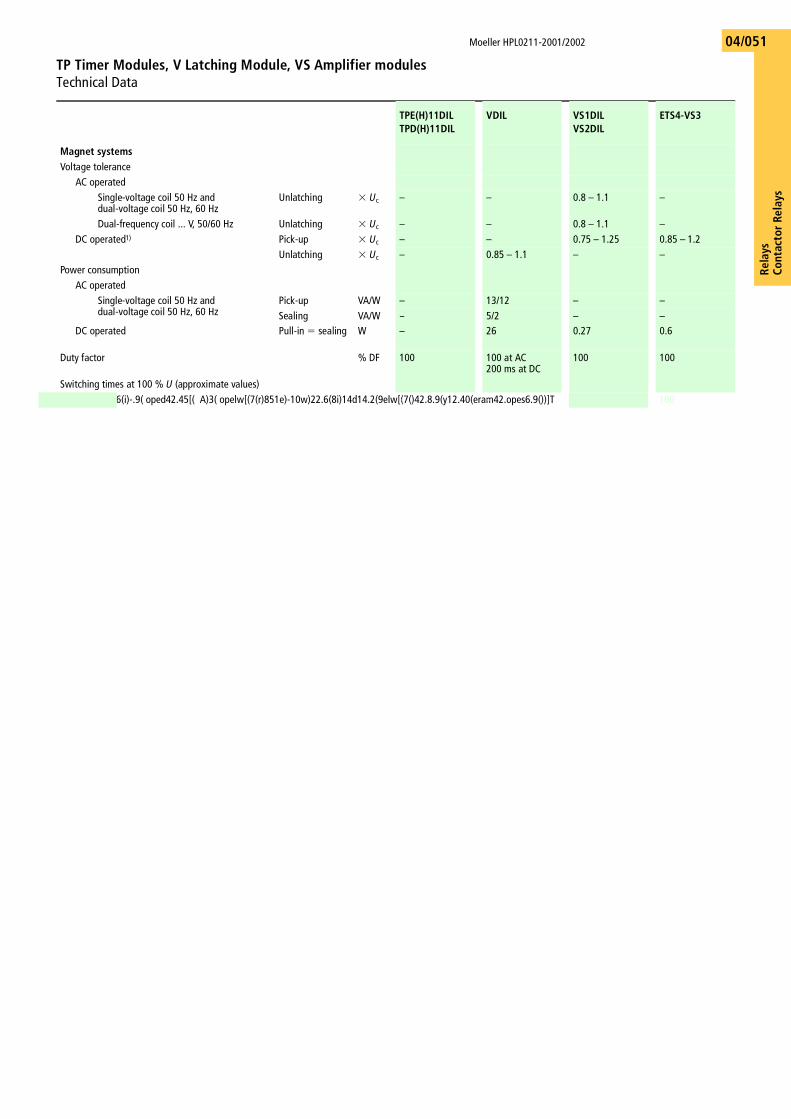
Rela
ysCo
ntac
tor
Rela
ys
Moeller HPL0211-2001/2002
TP Timer Modules, V Latching Module, VS Amplifier modulesTechnical Data
04/051
TPE(H)11DILTPD(H)11DIL
VDIL VS1DILVS2DIL
ETS4-VS3
Magnet systemsVoltage tolerance
AC operatedSingle-voltage coil 50 Hz and dual-voltage coil 50 Hz, 60 Hz
Unlatching � Uc – – 0.8 – 1.1 –
Dual-frequency coil ... V, 50/60 Hz Unlatching � Uc – – 0.8 – 1.1 –DC operated1) Pick-up � Uc – – 0.75 – 1.25 0.85 – 1.2
Unlatching � Uc – 0.85 – 1.1 – –Power consumption
AC operatedSingle-voltage coil 50 Hz anddual-voltage coil 50 Hz, 60 Hz
Pick-up VA/W – 13/12 – –Sealing VA/W – 5/2 – –
DC operated Pull-in � sealing W – 26 0.27 0.6
Duty factor % DF 100 100 at AC200 ms at DC
100 100
Switching times at 100 % U (approximate values)
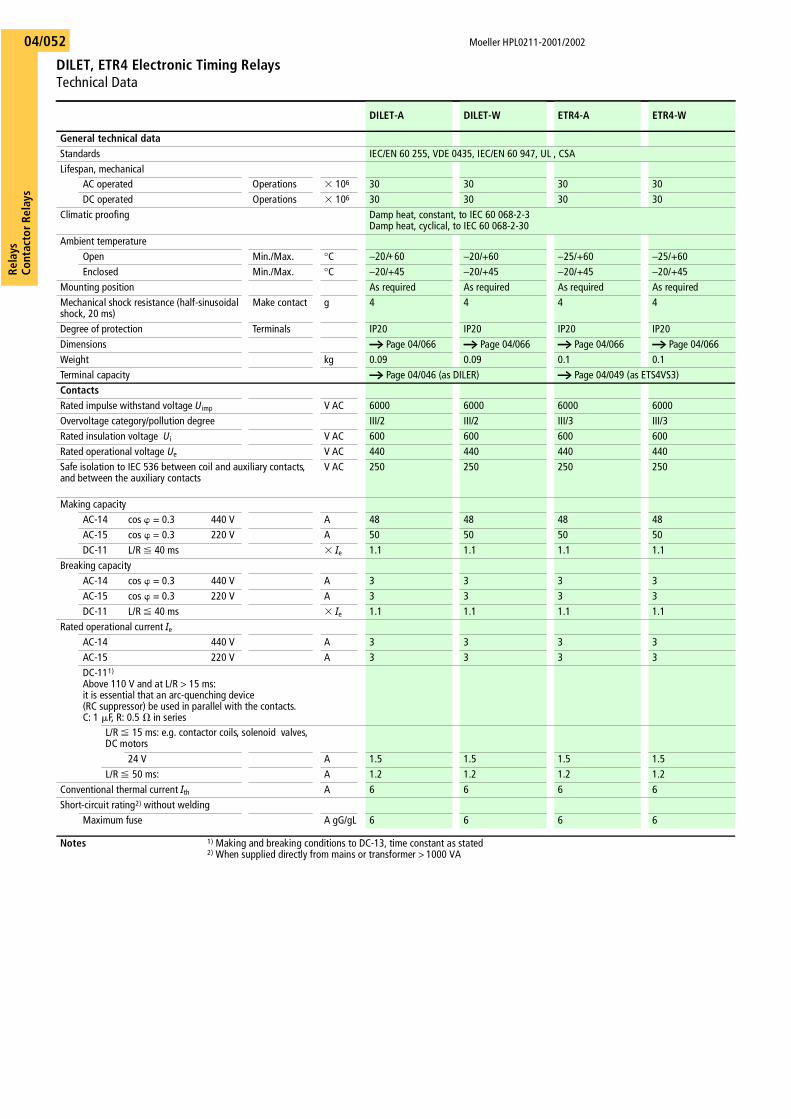
Moeller HPL0211-2001/2002
DILET, ETR4 Electronic Timing RelaysTechnical Data
Rela
ysCo
ntac
tor R
elay
s04/052
DILET-A DILET-W ETR4-A ETR4-W
General technical dataStandards IEC/EN 60 255, VDE 0435, IEC/EN 60 947, UL , CSALifespan, mechanical
AC operated Operations � 106 30 30 30 30DC operated Operations � 106 30 30 30 30
Climatic proofing Damp heat, constant, to IEC 60 068-2-3Damp heat, cyclical, to IEC 60 068-2-30
Ambient temperatureOpen Min./Max. °C −20/+60 −20/+60 −25/+60 −25/+60Enclosed Min./Max. °C −20/+45 −20/+45 −20/+45 −20/+45
Mounting position As required As required As required As requiredMechanical shock resistance (half-sinusoidal shock, 20 ms)
Make contact g 4 4 4 4
Degree of protection Terminals IP20 IP20 IP20 IP20Dimensions a Page 04/066 a Page 04/066 a Page 04/066 a Page 04/066Weight kg 0.09 0.09 0.1 0.1Terminal capacity a Page 04/046 (as DILER) a Page 04/049 (as ETS4VS3)ContactsRated impulse withstand voltage Uimp V AC 6000 6000 6000 6000Overvoltage category/pollution degree III/2 III/2 III/3 III/3Rated insulation voltage Ui V AC 600 600 600 600Rated operational voltage Ue V AC 440 440 440 440Safe isolation to IEC 536 between coil and auxiliary contacts, and between the auxiliary contacts
V AC 250 250 250 250
Making capacityAC-14 cos = 0.3 440 V A 48 48 48 48AC-15 cos = 0.3 220 V A 50 50 50 50DC-11 L/R � 40 ms � Ie 1.1 1.1 1.1 1.1
Breaking capacityAC-14 cos = 0.3 440 V A 3 3 3 3AC-15 cos = 0.3 220 V A 3 3 3 3DC-11 L/R � 40 ms � Ie 1.1 1.1 1.1 1.1
Rated operational current IeAC-14 440 V A 3 3 3 3AC-15 220 V A 3 3 3 3DC-111)
Above 110 V and at L/R > 15 ms:it is essential that an arc-quenching device (RC suppressor) be used in parallel with the contacts.C: 1 �F, R: 0.5 � in series
L/R � 15 ms: e.g. contactor coils, solenoid valves, DC motors
24 V A 1.5 1.5 1.5 1.5L/R � 50 ms: A 1.2 1.2 1.2 1.2
Conventional thermal current Ith A 6 6 6 6Short-circuit rating2) without welding
Maximum fuse A gG/gL 6 6 6 6
Notes 1) Making and breaking conditions to DC-13, time constant as stated 2) When supplied directly from mains or transformer > 1000 VA
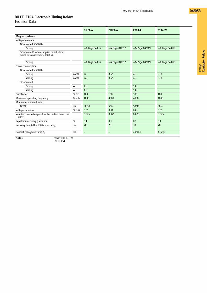
Rela
ysCo
ntac
tor
Rela
ys
Moeller HPL0211-2001/2002
DILET, ETR4 Electronic Timing Relays Technical Data
04/053
DILET-A DILET-W ETR4-A ETR4-W
Magnet systemsVoltage tolerance
AC operated 50/60 HzPick-up a Page 04/017 a Page 04/017 a Page 04/019 a Page 04/019
DC operated1) when supplied directly frommains or transformer > 1000 VA
Pick-up a Page 04/017 a Page 04/017 a Page 04/019 a Page 04/019Power consumption
AC operated 50/60 HzPick-up VA/W 2/– 0.5/– 2/– 0.5/–Sealing VA/W 2/– 0.5/– 2/– 0.5/–
DC operatedPick-up W 1.8 – 1.8 –Sealing W 1.8 – 1.8 –
Duty factor % DF 100 100 100 100Maximum operating frequency Ops./h 4000 4000 4000 4000Minimum command time
AC/DC ms 50/30 50/– 50/30 50/–Voltage variation % ∆ U 0.01 0.01 0.01 0.01Variation due to temperature fluctuation based on �20 °C
0.025 0.025 0.025 0.025
Repetition accuracy (deviation) % 0.1 0.1 0.1 0.1Recovery time (after 100% time delay) ms 70 70 70 70
Contact changeover time tu ms – – 4 (50)2) 4 (50)2)
Notes 1) Not DILET…-W2) ETR4-51
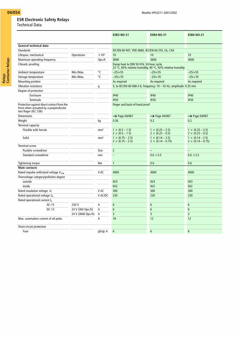
Moeller HPL0211-2001/2002
ESR Electronic Safety RelaysTechnical Data
Rela
ysCo
ntac
tor R
elay
s04/054
ESR3-NO-31 ESR4-NO-31 ESR4-NO-21
General technical dataStandards IEC/EN 60 947, VDE 0660, IEC/EN 60 255, UL, CSALifespan, mechanical Operations x106 10 10 10Maximum operating frequency Ops./h 3600 3600 3600Climatic proofing Damp heat to DIN 50 016: 24 hour cycle,
23 °C, 83% relative humidity, 40 °C, 92% relative humidityAmbient temperature Min./Max. °C –25/+55 –25/+55 –25/+55Storage temperature Min./Max. °C –25/+70 –25/+70 –25/+70Mounting position As required As required As requiredVibration resistance g 5, to IEC/EN 60 068-2-6, frequency: 10 – 55 Hz, amplitude: 0.35 mmDegree of protection
Enclosure IP40 IP40 IP40Terminals IP20 IP20 IP20
Protection against direct contact from the front when actuated by a perpendicular test finger (IEC 536)
Finger and back-of-hand proof
Dimensions a Page 04/067 a Page 04/067 a Page 04/067Weight kg 0.36 0.2 0.2Terminal capacity
Flexible with ferrule mm² 1 x (0.5 – 1.5)2 x (0.5 – 1.5)
1 x (0.25 – 2.5)2 x (0.25 – 0.5)
1 x (0.25 – 2.5)2 x (0.25 – 0.5)
Solid mm² 1 x (0.75 – 2.5)2 x (0.75 – 2.5)
1 x (0.14 – 2.5)2 x (0.14 – 0.75)
1 x (0.14 – 2.5)2 x (0.14 – 0.75)
Terminal screwPozidriv screwdriver Size 2 – –Standard screwdriver mm – 0.6 x3.5 0.6 x3.5
Tightening torque Nm 1 0.6 0.6Main contactsRated impulse withstand voltage Uimp V AC 4000 4000 4000Overvoltage category/pollution degree
outside III/3 III/3 III/3 inside III/2 III/2 III/2
Rated insulation voltage Ui V AC 300 300 300Rated operational voltage Ue V AC/DC 230 230 230Rated operational current Ie
AC-15 230 V A 6 6 6DC-13 24 V (360 Ops./h) A 6 6 6
24 V (3600 Ops./h) A 3 3 3Max. summation current of all poles A 18 12 12
Short-circuit protectionFuse gG/gL A 6 6 6
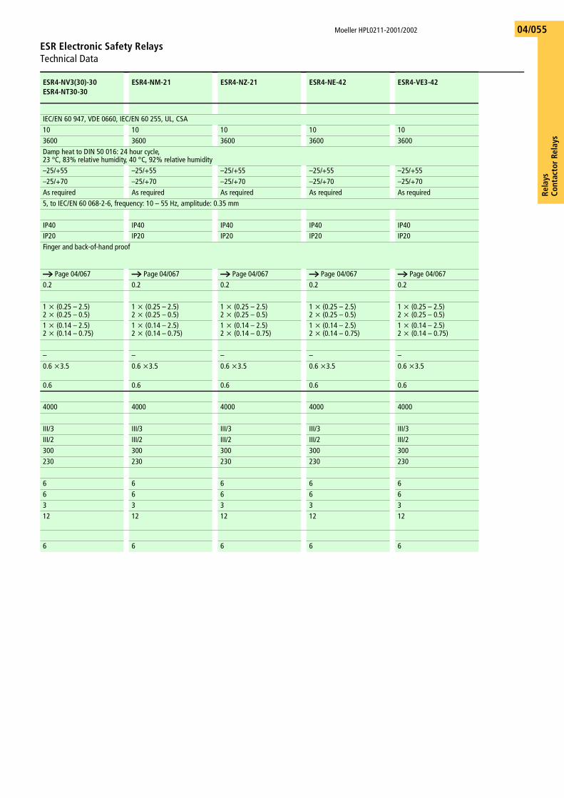
Rela
ysCo
ntac
tor
Rela
ys
Moeller HPL0211-2001/2002
ESR Electronic Safety RelaysTechnical Data
04/055
ESR4-NV3(30)-30ESR4-NT30-30
ESR4-NM-21 ESR4-NZ-21 ESR4-NE-42 ESR4-VE3-42
IEC/EN 60 947, VDE 0660, IEC/EN 60 255, UL, CSA10 10 10 10 103600 3600 3600 3600 3600Damp heat to DIN 50 016: 24 hour cycle,23 °C, 83% relative humidity, 40 °C, 92% relative humidity–25/+55 –25/+55 –25/+55 –25/+55 –25/+55–25/+70 –25/+70 –25/+70 –25/+70 –25/+70As required As required As required As required As required5, to IEC/EN 60 068-2-6, frequency: 10 – 55 Hz, amplitude: 0.35 mm
IP40 IP40 IP40 IP40 IP40IP20 IP20 IP20 IP20 IP20Finger and back-of-hand proof
a Page 04/067 a Page 04/067 a Page 04/067 a Page 04/067 a Page 04/0670.2 0.2 0.2 0.2 0.2
1 x (0.25 – 2.5)2 x (0.25 – 0.5)
1 x (0.25 – 2.5)2 x (0.25 – 0.5)
1 x (0.25 – 2.5)2 x (0.25 – 0.5)
1 x (0.25 – 2.5)2 x (0.25 – 0.5)
1 x (0.25 – 2.5)2 x (0.25 – 0.5)
1 x (0.14 – 2.5)2 x (0.14 – 0.75)
1 x (0.14 – 2.5)2 x (0.14 – 0.75)
1 x (0.14 – 2.5)2 x (0.14 – 0.75)
1 x (0.14 – 2.5)2 x (0.14 – 0.75)
1 x (0.14 – 2.5)2 x (0.14 – 0.75)
– – – – –0.6 x3.5 0.6 x3.5 0.6 x3.5 0.6 x3.5 0.6 x3.5
0.6 0.6 0.6 0.6 0.6
4000 4000 4000 4000 4000
III/3 III/3 III/3 III/3 III/3 III/2 III/2 III/2 III/2 III/2300 300 300 300 300230 230 230 230 230
6 6 6 6 66 6 6 6 63 3 3 3 312 12 12 12 12
6 6 6 6 6
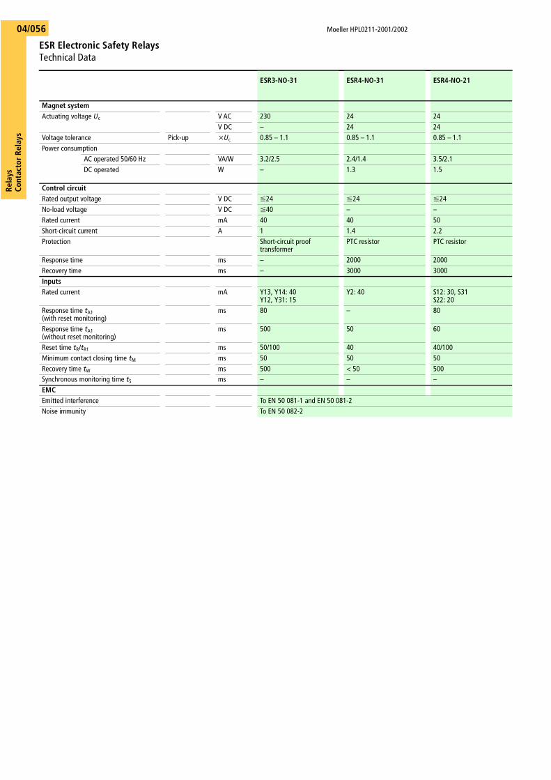
Moeller HPL0211-2001/2002
ESR Electronic Safety RelaysTechnical Data
Rela
ysCo
ntac
tor R
elay
s04/056
ESR3-NO-31 ESR4-NO-31 ESR4-NO-21
Magnet systemActuating voltage Uc V AC 230 24 24
V DC – 24 24Voltage tolerance Pick-up xUc 0.85 – 1.1 0.85 – 1.1 0.85 – 1.1Power consumption
AC operated 50/60 Hz VA/W 3.2/2.5 2.4/1.4 3.5/2.1DC operated W – 1.3 1.5
Control circuitRated output voltage V DC F24 F24 F24No-load voltage V DC F40 – –Rated current mA 40 40 50Short-circuit current A 1 1.4 2.2Protection Short-circuit proof
transformerPTC resistor PTC resistor
Response time ms – 2000 2000Recovery time ms – 3000 3000InputsRated current mA Y13, Y14: 40
Y12, Y31: 15Y2: 40 S12: 30, S31
S22: 20Response time tA1 (with reset monitoring)
ms 80 – 80
Response time tA1 (without reset monitoring)
ms 500 50 60
Reset time tR/tR1 ms 50/100 40 40/100Minimum contact closing time tM ms 50 50 50Recovery time tW ms 500 < 50 500Synchronous monitoring time tS ms – – –EMCEmitted interference To EN 50 081-1 and EN 50 081-2Noise immunity To EN 50 082-2
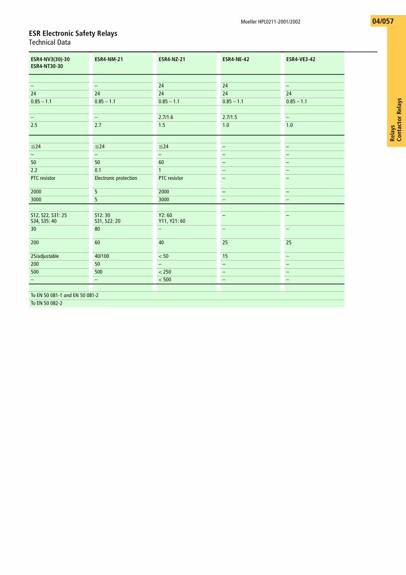
Rela
ysCo
ntac
tor
Rela
ys
Moeller HPL0211-2001/2002
ESR Electronic Safety RelaysTechnical Data
04/057
ESR4-NV3(30)-30ESR4-NT30-30
ESR4-NM-21 ESR4-NZ-21 ESR4-NE-42 ESR4-VE3-42
– – 24 24 –24 24 24 24 240.85 – 1.1 0.85 – 1.1 0.85 – 1.1 0.85 – 1.1 0.85 – 1.1
– – 2.7/1.6 2.7/1.5 –2.5 2.7 1.5 1.0 1.0
F24 F24 F24 – –– – – – –50 50 60 – –2.2 0.1 1 – –PTC resistor Electronic protection PTC resistor – –
2000 5 2000 – –3000 5 3000 – –
S12, S22, S31: 25S34, S35: 40
S12: 30S31, S22: 20
Y2: 60Y11, Y21: 60
– –
30 80 – – –
200 60 40 25 25
25/adjustable 40/100 < 50 15 –200 50 – – –500 500 < 250 – –– – < 500 – –
To EN 50 081-1 and EN 50 081-2To EN 50 082-2
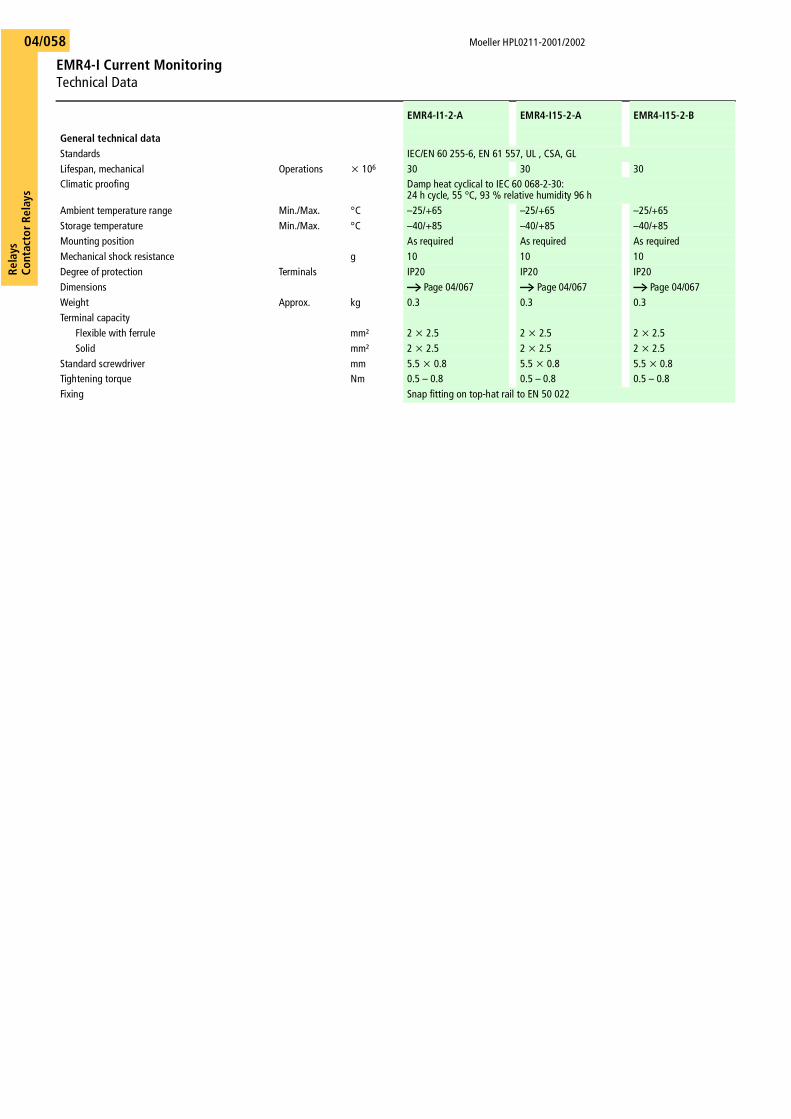
Moeller HPL0211-2001/2002
EMR4-I Current MonitoringTechnical Data
Rela
ysCo
ntac
tor R
elay
s04/058
EMR4-I1-2-A EMR4-I15-2-A EMR4-I15-2-B
General technical dataStandards IEC/EN 60 255-6, EN 61 557, UL , CSA, GLLifespan, mechanical Operations x 106 30 30 30Climatic proofing Damp heat cyclical to IEC 60 068-2-30:
24 h cycle, 55 °C, 93 % relative humidity 96 hAmbient temperature range Min./Max. °C –25/+65 –25/+65 –25/+65Storage temperature Min./Max. °C –40/+85 –40/+85 –40/+85Mounting position As required As required As requiredMechanical shock resistance g 10 10 10Degree of protection Terminals IP20 IP20 IP20Dimensions A Page 04/067 A Page 04/067 A Page 04/067Weight Approx. kg 0.3 0.3 0.3Terminal capacity
Flexible with ferrule mm² 2 x 2.5 2 x 2.5 2 x 2.5Solid mm² 2 x 2.5 2 x 2.5 2 x 2.5
Standard screwdriver mm 5.5 x 0.8 5.5 x 0.8 5.5 x 0.8Tightening torque Nm 0.5 – 0.8 0.5 – 0.8 0.5 – 0.8Fixing Snap fitting on top-hat rail to EN 50 022
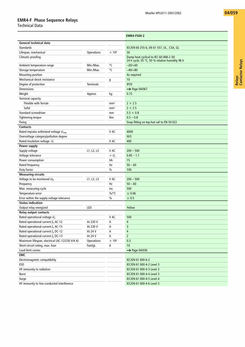
Rela
ysCo
ntac
tor
Rela
ys
Moeller HPL0211-2001/2002
EMR4-F Phase Sequence RelaysTechnical Data
04/059
EMR4-F500-2
General technical dataStandards IEC/EN 60 255-6, EN 61 557, UL , CSA, GLLifespan, mechanical Operations x 106 30Climatic proofing Damp heat cyclical to IEC 60 068-2-30:
24 h cycle, 55 °C, 93 % relative humidity 96 hAmbient temperature range Min./Max. °C –20/+60Storage temperature Min./Max. °C –40/+80Mounting position As requiredMechanical shock resistance g 10Degree of protection Terminals IP20Dimensions a Page 04/067Weight Approx. kg 0.15Terminal capacity
Flexible with ferrule mm² 2 x 2.5Solid mm² 2 x 2.5
Standard screwdriver mm 5.5 x 0.8Tightening torque Nm 0.5 – 0.8Fixing Snap fitting on top-hat rail to EN 50 022ContactsRated impulse withstand voltage Uimp V AC 4000Overvoltage category/pollution degree III/3Rated insulation voltage Ui V AC 400Power supplySupply voltage L1, L2, L3 V AC 200 – 500Voltage tolerance x Uc 0.85 – 1.1Power consumption VA 15Rated frequency Hz 50 – 60Duty factor % 100Measuring circuitsVoltage to be monitored UN L1, L2, L3 V AC 200 – 500Frequency Hz 50 – 60Max. measuring cycle ms 500Temperature error %/°C F 0.06Error within the supply voltage tolerance % F 0.5Status indicationOutput relay energized LED YellowRelay output contactsRated operational voltage Ue V AC 500Rated operational current Ie AC-12 At 230 V A 4Rated operational current Ie AC-15 At 230 V A 3Rated operational current Ie DC-12 At 24 V A 4Rated operational current Ie DC-13 At 24 V A 2Maximum lifespan, electrical (AC-12/230 V/4 A) Operations x 106 0.3Short-circuit rating, max. fuse Fast/gL A 10Load limit curves a Page 04/036EMCElectromagnetic compatibility IEC/EN 61 000-6-2ESD IEC/EN 61 000-4-2 Level 3HF immunity to radiation IEC/EN 61 000-4-3 Level 3Burst IEC/EN 61 000-4-4 Level 3Surge IEC/EN 61 000-4-5 Level 4HF immunity to line-conducted interference IEC/EN 61 000-4-6 Level 3
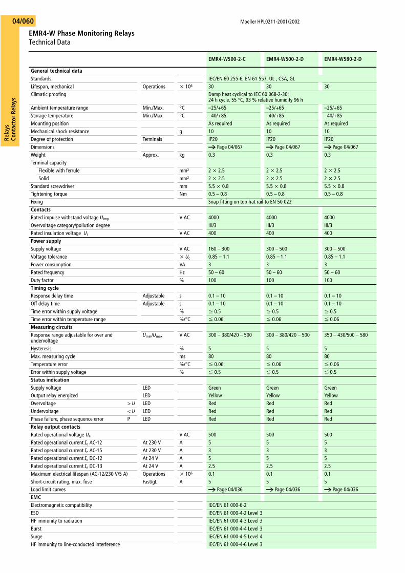
Moeller HPL0211-2001/2002
EMR4-W Phase Monitoring RelaysTechnical Data
Rela
ysCo
ntac
tor R
elay
s04/060
EMR4-W500-2-C EMR4-W500-2-D EMR4-W580-2-D
General technical dataStandards IEC/EN 60 255-6, EN 61 557, UL , CSA, GLLifespan, mechanical Operations x 106 30 30 30Climatic proofing Damp heat cyclical to IEC 60 068-2-30:
24 h cycle, 55 °C, 93 % relative humidity 96 hAmbient temperature range Min./Max. °C –25/+65 –25/+65 –25/+65Storage temperature Min./Max. °C –40/+85 –40/+85 –40/+85Mounting position As required As required As requiredMechanical shock resistance g 10 10 10Degree of protection Terminals IP20 IP20 IP20Dimensions a Page 04/067 a Page 04/067 a Page 04/067Weight Approx. kg 0.3 0.3 0.3Terminal capacity
Flexible with ferrule mm² 2 x 2.5 2 x 2.5 2 x 2.5Solid mm² 2 x 2.5 2 x 2.5 2 x 2.5
Standard screwdriver mm 5.5 x 0.8 5.5 x 0.8 5.5 x 0.8Tightening torque Nm 0.5 – 0.8 0.5 – 0.8 0.5 – 0.8Fixing Snap fitting on top-hat rail to EN 50 022ContactsRated impulse withstand voltage Uimp V AC 4000 4000 4000Overvoltage category/pollution degree III/3 III/3 III/3Rated insulation voltage Ui V AC 400 400 400Power supplySupply voltage V AC 160 – 300 300 – 500 300 – 500Voltage tolerance x Uc 0.85 – 1.1 0.85 – 1.1 0.85 – 1.1Power consumption VA 3 3 3Rated frequency Hz 50 – 60 50 – 60 50 – 60Duty factor % 100 100 100Timing cycleResponse delay time Adjustable s 0.1 – 10 0.1 – 10 0.1 – 10Off delay time Adjustable s 0.1 – 10 0.1 – 10 0.1 – 10Time error within supply voltage % F 0.5 F 0.5 F 0.5Time error within temperature range %/°C F 0.06 F 0.06 F 0.06Measuring circuitsResponse range adjustable for over and undervoltage
Umin/Umax V AC 300 – 380/420 – 500 300 – 380/420 – 500 350 – 430/500 – 580
Hysteresis % 5 5 5Max. measuring cycle ms 80 80 80Temperature error %/°C F 0.06 F 0.06 F 0.06Error within supply voltage % F 0.5 F 0.5 F 0.5Status indicationSupply voltage LED Green Green GreenOutput relay energized LED Yellow Yellow YellowOvervoltage > U LED Red Red RedUndervoltage < U LED Red Red RedPhase failure, phase sequence error P LED Red Red RedRelay output contactsRated operational voltage Ue V AC 500 500 500Rated operational current Ie AC-12 At 230 V A 5 5 5Rated operational current Ie AC-15 At 230 V A 3 3 3Rated operational current Ie DC-12 At 24 V A 5 5 5Rated operational current Ie DC-13 At 24 V A 2.5 2.5 2.5Maximum electrical lifespan (AC-12/230 V/5 A) Operations x 106 0.1 0.1 0.1Short-circuit rating, max. fuse Fast/gL A 5 5 5Load limit curves a Page 04/036 a Page 04/036 a Page 04/036EMCElectromagnetic compatibility IEC/EN 61 000-6-2ESD IEC/EN 61 000-4-2 Level 3HF immunity to radiation IEC/EN 61 000-4-3 Level 3Burst IEC/EN 61 000-4-4 Level 3Surge IEC/EN 61 000-4-5 Level 4HF immunity to line-conducted interference IEC/EN 61 000-4-6 Level 3
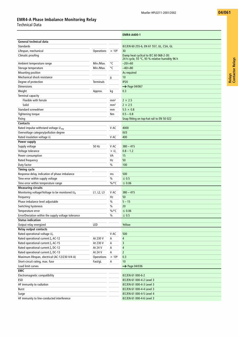
Rela
ysCo
ntac
tor
Rela
ys
Moeller HPL0211-2001/2002
EMR4-A Phase Imbalance Monitoring RelayTechnical Data
04/061
EMR4-A400-1
General technical dataStandards IEC/EN 60 255-6, EN 61 557, UL, CSA, GLLifespan, mechanical Operations x 106 30Climatic proofing Damp heat cyclical to IEC 60 068-2-30:
24 h cycle, 55 °C, 93 % relative humidity 96 hAmbient temperature range Min./Max. °C –20/+60Storage temperature Min./Max. °C –40/+80Mounting position As requiredMechanical shock resistance g 10Degree of protection Terminals IP20Dimensions a Page 04/067Weight Approx. kg 0.3Terminal capacity
Flexible with ferrule mm² 2 x 2.5Solid mm² 2 x 2.5
Standard screwdriver mm 5.5 x 0.8Tightening torque Nm 0.5 – 0.8Fixing Snap fitting on top-hat rail to EN 50 022ContactsRated impulse withstand voltage Uimp V AC 4000Overvoltage category/pollution degree III/3Rated insulation voltage Ui V AC 400Power supplySupply voltage 50 Hz V AC 380 – 415Voltage tolerance x Uc 0.8 – 1.2Power consumption VA 15Rated frequency Hz 50Duty factor % 100Timing cycleResponse delay, indication of phase imbalance ms 500Time error within supply voltage % F 0.5Time error within temperature range %/°C F 0.06Measuring circuitsMonitoring voltage/Voltage to be monitored UN L1, L2, L3 V AC 380 – 415Frequency Hz 50Phase imbalance level adjustable % 5 – 15Switching hysteresis % 20Temperature error %/°C F 0.06Error/Deviation within the supply voltage tolerance % F 0.5Status indicationOutput relay energized LED YellowRelay output contactsRated operational voltage Ue V AC 500Rated operational current Ie AC-12 At 230 V A 4Rated operational current Ie AC-15 At 230 V A 3Rated operational current Ie DC-12 At 24 V A 4Rated operational current Ie DC-13 At 24 V A 2Maximum lifespan, electrical (AC-12/230 V/4 A) Operations x 106 0.3Short-circuit rating, max. fuse Fast/gL A 10Load limit curves a Page 04/036EMCElectromagnetic compatibility IEC/EN 61 000-6-2ESD IEC/EN 61 000-4-2 Level 3HF immunity to radiation IEC/EN 61 000-4-3 Level 3Burst IEC/EN 61 000-4-4 Level 3Surge IEC/EN 61 000-4-5 Level 4HF immunity to line-conducted interference IEC/EN 61 000-4-6 Level 3
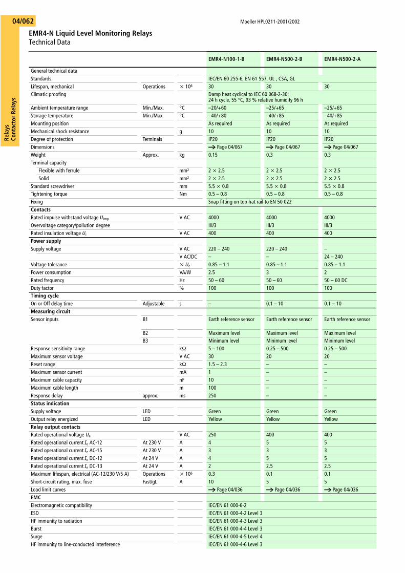
Moeller HPL0211-2001/2002
EMR4-N Liquid Level Monitoring RelaysTechnical Data
Rela
ysCo
ntac
tor R
elay
s04/062
EMR4-N100-1-B EMR4-N500-2-B EMR4-N500-2-A
General technical dataStandards IEC/EN 60 255-6, EN 61 557, UL , CSA, GLLifespan, mechanical Operations x 106 30 30 30Climatic proofing Damp heat cyclical to IEC 60 068-2-30:
24 h cycle, 55 °C, 93 % relative humidity 96 hAmbient temperature range Min./Max. °C –20/+60 –25/+65 –25/+65Storage temperature Min./Max. °C –40/+80 –40/+85 –40/+85Mounting position As required As required As requiredMechanical shock resistance g 10 10 10Degree of protection Terminals IP20 IP20 IP20Dimensions a Page 04/067 a Page 04/067 a Page 04/067Weight Approx. kg 0.15 0.3 0.3Terminal capacity
Flexible with ferrule mm² 2 x 2.5 2 x 2.5 2 x 2.5Solid mm² 2 x 2.5 2 x 2.5 2 x 2.5
Standard screwdriver mm 5.5 x 0.8 5.5 x 0.8 5.5 x 0.8Tightening torque Nm 0.5 – 0.8 0.5 – 0.8 0.5 – 0.8Fixing Snap fitting on top-hat rail to EN 50 022ContactsRated impulse withstand voltage Uimp V AC 4000 4000 4000Overvoltage category/pollution degree III/3 III/3 III/3Rated insulation voltage Ui V AC 400 400 400Power supplySupply voltage V AC 220 – 240 220 – 240 –
V AC/DC – – 24 – 240Voltage tolerance x Uc 0.85 – 1.1 0.85 – 1.1 0.85 – 1.1Power consumption VA/W 2.5 3 2Rated frequency Hz 50 – 60 50 – 60 50 – 60 DCDuty factor % 100 100 100Timing cycleOn or Off delay time Adjustable s – 0.1 – 10 0.1 – 10Measuring circuitSensor inputs B1 Earth reference sensor Earth reference sensor Earth reference sensor
B2 Maximum level Maximum level Maximum levelB3 Minimum level Minimum level Minimum level
Response sensitivity range kO 5 – 100 0.25 – 500 0.25 – 500Maximum sensor voltage V AC 30 20 20Reset range kO 1.5 – 2.3 – –Maximum sensor current mA 1 – –Maximum cable capacity nF 10 – –Maximum cable length m 100 – –Response delay approx. ms 250 – –Status indicationSupply voltage LED Green Green GreenOutput relay energized LED Yellow Yellow YellowRelay output contactsRated operational voltage Ue V AC 250 400 400Rated operational current Ie AC-12 At 230 V A 4 5 5Rated operational current Ie AC-15 At 230 V A 3 3 3Rated operational current Ie DC-12 At 24 V A 4 5 5Rated operational current Ie DC-13 At 24 V A 2 2.5 2.5Maximum lifespan, electrical (AC-12/230 V/5 A) Operations x 106 0.3 0.1 0.1Short-circuit rating, max. fuse Fast/gL A 10 5 5Load limit curves a Page 04/036 a Page 04/036 a Page 04/036EMCElectromagnetic compatibility IEC/EN 61 000-6-2ESD IEC/EN 61 000-4-2 Level 3HF immunity to radiation IEC/EN 61 000-4-3 Level 3Burst IEC/EN 61 000-4-4 Level 3Surge IEC/EN 61 000-4-5 Level 4HF immunity to line-conducted interference IEC/EN 61 000-4-6 Level 3
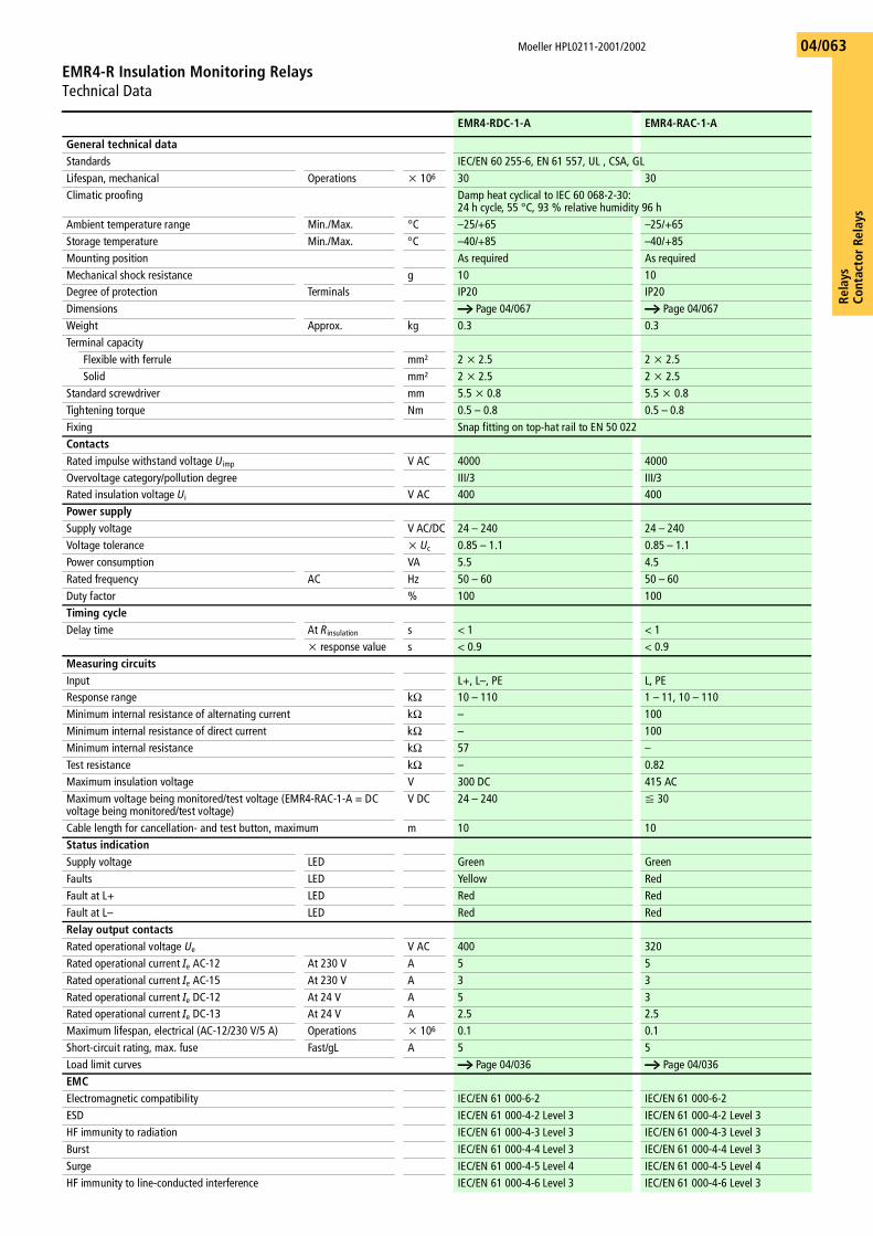
Rela
ysCo
ntac
tor
Rela
ys
Moeller HPL0211-2001/2002
EMR4-R Insulation Monitoring RelaysTechnical Data
04/063
EMR4-RDC-1-A EMR4-RAC-1-A
General technical dataStandards IEC/EN 60 255-6, EN 61 557, UL , CSA, GLLifespan, mechanical Operations x 106 30 30Climatic proofing Damp heat cyclical to IEC 60 068-2-30:
24 h cycle, 55 °C, 93 % relative humidity 96 hAmbient temperature range Min./Max. °C –25/+65 –25/+65Storage temperature Min./Max. °C –40/+85 –40/+85Mounting position As required As requiredMechanical shock resistance g 10 10Degree of protection Terminals IP20 IP20Dimensions a Page 04/067 a Page 04/067Weight Approx. kg 0.3 0.3Terminal capacity
Flexible with ferrule mm² 2 x 2.5 2 x 2.5Solid mm² 2 x 2.5 2 x 2.5
Standard screwdriver mm 5.5 x 0.8 5.5 x 0.8Tightening torque Nm 0.5 – 0.8 0.5 – 0.8Fixing Snap fitting on top-hat rail to EN 50 022ContactsRated impulse withstand voltage Uimp V AC 4000 4000Overvoltage category/pollution degree III/3 III/3Rated insulation voltage Ui V AC 400 400Power supplySupply voltage V AC/DC 24 – 240 24 – 240Voltage tolerance x Uc 0.85 – 1.1 0.85 – 1.1Power consumption VA 5.5 4.5Rated frequency AC Hz 50 – 60 50 – 60Duty factor % 100 100Timing cycleDelay time At Rinsulation s < 1 < 1
x response value s < 0.9 < 0.9Measuring circuitsInput L+, L–, PE L, PEResponse range kO 10 – 110 1 – 11, 10 – 110Minimum internal resistance of alternating current kO – 100Minimum internal resistance of direct current kO – 100Minimum internal resistance kO 57 –Test resistance kO – 0.82Maximum insulation voltage V 300 DC 415 ACMaximum voltage being monitored/test voltage (EMR4-RAC-1-A = DC voltage being monitored/test voltage)
V DC 24 – 240 F 30
Cable length for cancellation- and test button, maximum m 10 10Status indicationSupply voltage LED Green GreenFaults LED Yellow RedFault at L+ LED Red RedFault at L– LED Red RedRelay output contactsRated operational voltage Ue V AC 400 320Rated operational current Ie AC-12 At 230 V A 5 5Rated operational current Ie AC-15 At 230 V A 3 3Rated operational current Ie DC-12 At 24 V A 5 3Rated operational current Ie DC-13 At 24 V A 2.5 2.5Maximum lifespan, electrical (AC-12/230 V/5 A) Operations x 106 0.1 0.1Short-circuit rating, max. fuse Fast/gL A 5 5Load limit curves a Page 04/036 a Page 04/036EMCElectromagnetic compatibility IEC/EN 61 000-6-2 IEC/EN 61 000-6-2ESD IEC/EN 61 000-4-2 Level 3 IEC/EN 61 000-4-2 Level 3HF immunity to radiation IEC/EN 61 000-4-3 Level 3 IEC/EN 61 000-4-3 Level 3Burst IEC/EN 61 000-4-4 Level 3 IEC/EN 61 000-4-4 Level 3Surge IEC/EN 61 000-4-5 Level 4 IEC/EN 61 000-4-5 Level 4HF immunity to line-conducted interference IEC/EN 61 000-4-6 Level 3 IEC/EN 61 000-4-6 Level 3
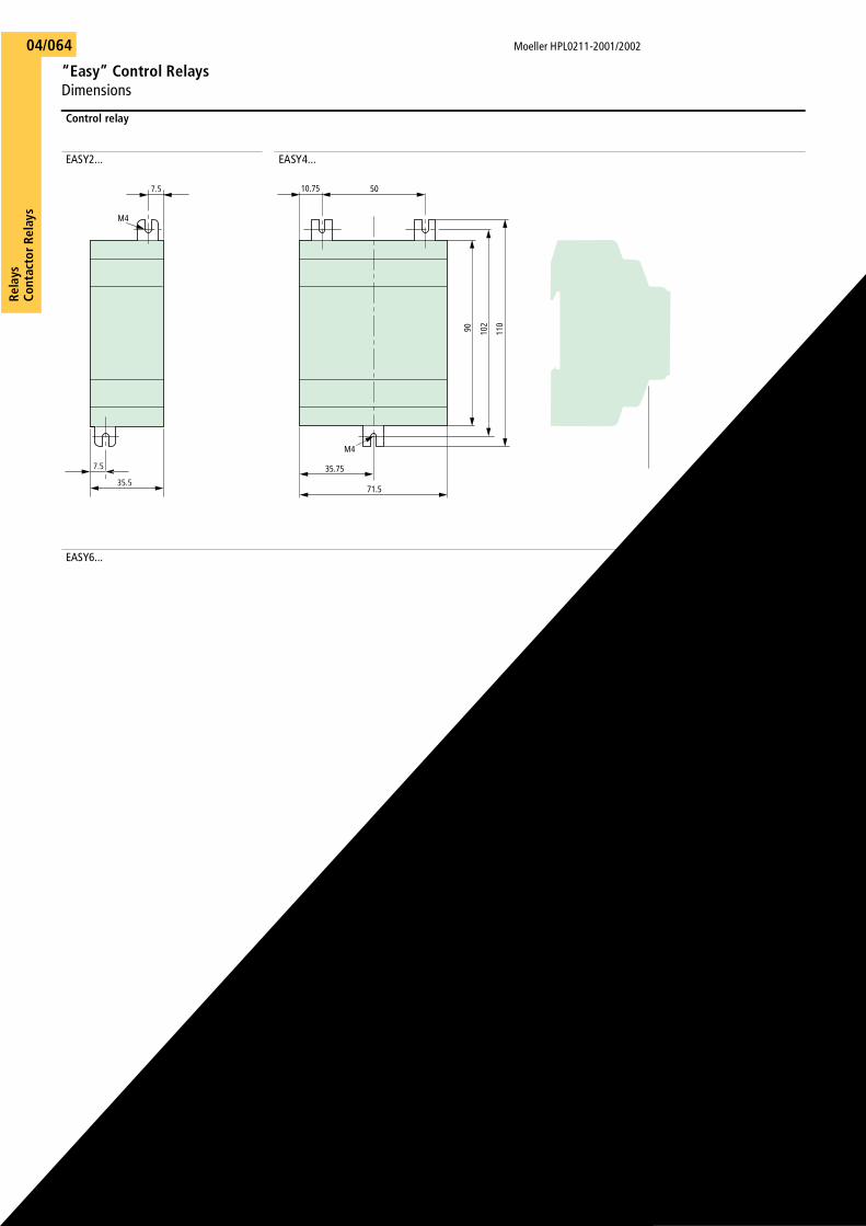
Moeller HPL0211-2001/2002
“Easy” Control RelaysDimensions
Rela
ysCo
ntac
tor R
elay
s04/064
Control relay
EASY2... EASY4...
EASY6...
M4
7.5
35.5
7.5
90 102
110
71.5
M4
10.75 50
35.75
Rela
ysCo
ntac
tor
Rela
ys
Moeller HPL0211-2001/2002
DILER Mini Contactor RelaysDimensions
04/065
Mini contactor relays
DILER-...DILER-...-G
DILER-... + ...DILEDILER-...-G + ...DILE
DILER-... + HDILEDILER-...-G + HDILE
2DILER-... + MVDILE2DILER-...-G + MVDILE
DILER-... + RCDILEDILER-...-G + VGDILE
2DILER-... + MVDILE + ...DILE2DILER-...-G + MVDILE + ...DILE
DILER-... + TDDILE24
Suppressors, amplifier modules
RCBDIL,FDBDILVGBDILVS1(2)DIL
4558525,54583585035M4455865,34345
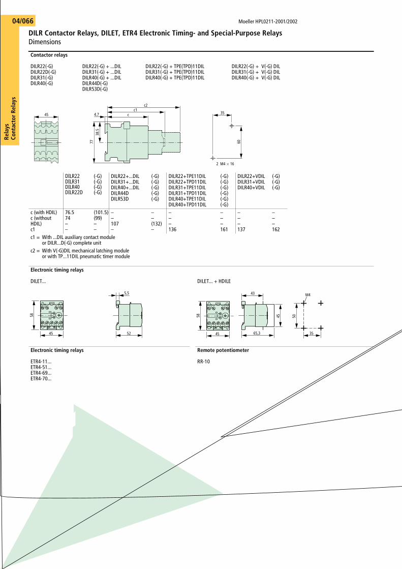
Moeller HPL0211-2001/2002
DILR Contactor Relays, DILET, ETR4 Electronic Timing- and Special-Purpose Relays Dimensions
Rela
ysCo
ntac
tor R
elay
s04/066
Contactor relays
DILR22(-G)DILR22D(-G)DILR31(-G)DILR40(-G)
DILR22(-G) + ...DILDILR31(-G) + ...DILDILR40(-G) + ...DILDILR44D(-G)DILR53D(-G)
DILR22(-G) + TPE(TPD)11DILDILR31(-G) + TPE(TPD)11DILDILR40(-G) + TPE(TPD)11DIL
DILR22(-G) + V(-G) DILDILR31(-G) + V(-G) DILDILR40(-G) + V(-G) DIL
DILR22DILR31DILR40DILR22D
(-G)(-G)(-G)(-G)
DILR22+...DILDILR31+...DILDILR40+...DILDILR44DDILR53D
(-G)(-G)(-G)(-G)(-G)
DILR22+TPE11DILDILR22+TPD11DILDILR31+TPE11DILDILR31+TPD11DILDILR40+TPE11DILDILR40+TPD11DIL
(-G)(-G)(-G)(-G)(-G)(-G)
DILR22+VDILDILR31+VDILDILR40+VDIL
(-G)(-G)(-G)
c (with HDIL)c (without HDIL)c1
76.574––
(101.5)(99)––
––107–
––(132)–
–––136
–––161
–––137
–––162
c1 = With ...DIL auxiliary contact module or DILR...D(-G) complete unit
c2 = With V(-G)DIL mechanical latching module or with TP...11DIL pneumatic timer module
Electronic timing relays
DILET... DILET... + HDILE
Electronic timing relays
ETR4-11...ETR4-51...ETR4-69...ETR4-70...
Remote potentiometer
RR-10
35
60
2 M4 16
45
c2c1
c4.7
7738
.5
45
58
52
5,5
65,3
43
45 50
35
M4
45
58
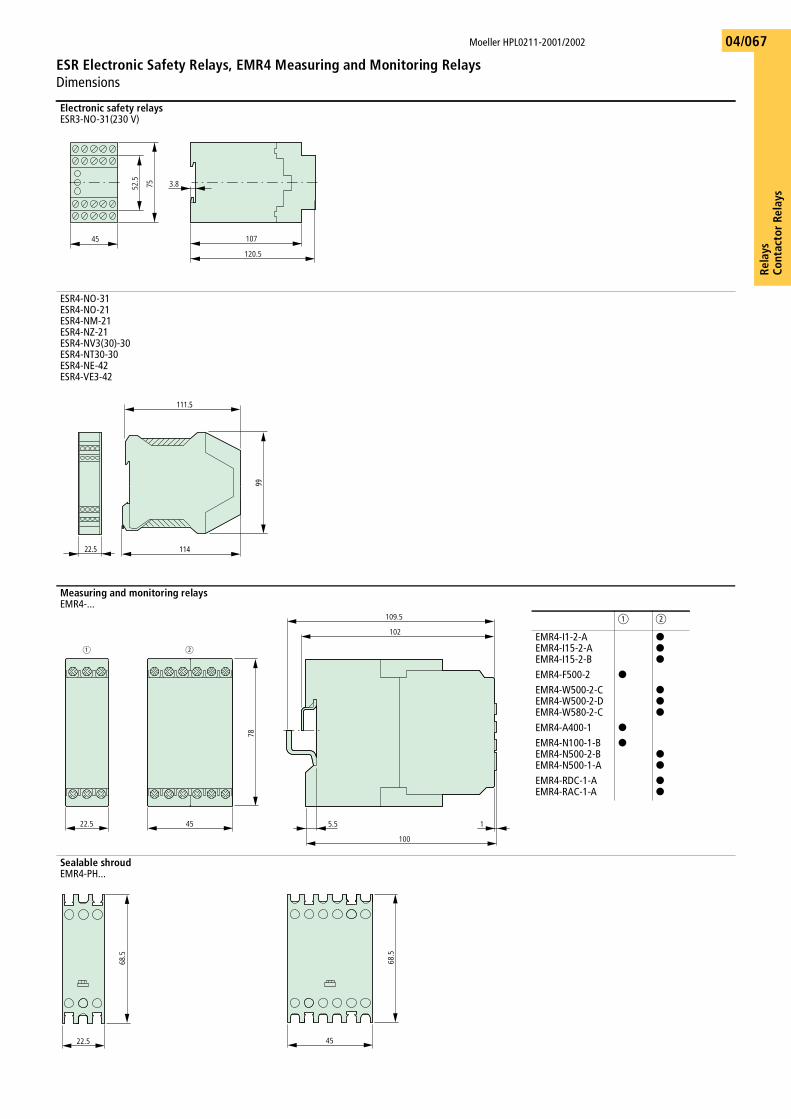
Rela
ysCo
ntac
tor
Rela
ys
Moeller HPL0211-2001/2002
ESR Electronic Safety Relays, EMR4 Measuring and Monitoring RelaysDimensions
04/067
Electronic safety relaysESR3-NO-31(230 V)
ESR4-NO-31ESR4-NO-21ESR4-NM-21ESR4-NZ-21ESR4-NV3(30)-30ESR4-NT30-30ESR4-NE-42ESR4-VE3-42
Measuring and monitoring relaysEMR4-...
Sealable shroudEMR4-PH...
107
120.5
45
52.5
75 3.8
114
99
22.5
111.5
109.5
102
78
5.5 1
100
45 22.5
a b
a b
EMR4-I1-2-AEMR4-I15-2-AEMR4-I15-2-B
KKK
EMR4-F500-2 K
EMR4-W500-2-CEMR4-W500-2-DEMR4-W580-2-C
KKK
EMR4-A400-1 K
EMR4-N100-1-BEMR4-N500-2-BEMR4-N500-1-A
KKK
EMR4-RDC-1-AEMR4-RAC-1-A
KK
22.5
68.5
45
68.5