Centrales II Orlando Centrales II OrlandoCentrales II Orlandov
Upload
hoangtuyenCategory
view
217download
0
ANEXOS

BRANCO

I. ANEXO I
Pavimento Metálico Miniquadrícula 400

ANEXO I–2
BRANCO

ANEXO I–3
Pavimento Metálico – Miniquadricula 400

ANEXO I–4

ANEXO II–1
II. ANEXO II
Caraterísticas Geométricas e Elásticas das Chapas dos Revestimentos dos Alçados e da Cobertura

ANEXO II–2
o
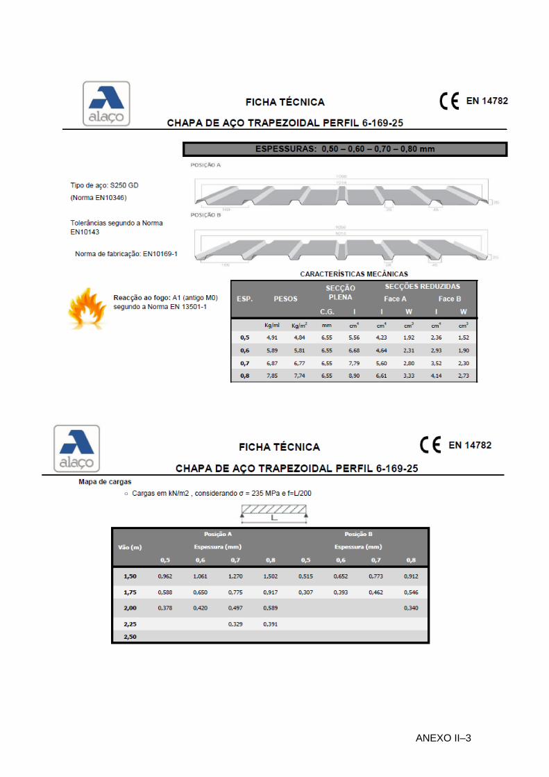
ANEXO II–3

ANEXO II–4

ANEXO III–1
III. ANEXO III
Relatórios de Dimensionamento das Ligações Aparafusadas
"Robot Structural Analysis Professional"

ANEXO III–2
branco

ANEXO III–3
Autodesk Robot Structural Analysis Professional 2014-Student Version
Design of fixed beam-to-column connection
EN 1993-1-8:2005/AC:2009
Ratio 0.63
GENERAL
Connection no.: 6
Connection name: Frame knee
GEOMETRY
COLUMN
Section: HEA 180
= -90.0 [Deg] Inclination angle
hc = 171 [mm] Height of column section
bfc = 180 [mm] Width of column section
twc = 6 [mm] Thickness of the web of column section
tfc = 10 [mm] Thickness of the flange of column section
rc = 15 [mm] Radius of column section fillet
Ac = 45.25 [cm2] Cross-sectional area of a column
Ixc = 2510.29 [cm4] Moment of inertia of the column section
Material: S 235
fyc = 235000.00 [kPa] Resistance

ANEXO III–4
BEAM
Section: IPE 240
= 0.0 [Deg] Inclination angle
hb = 240 [mm] Height of beam section
bf = 120 [mm] Width of beam section
twb = 6 [mm] Thickness of the web of beam section
tfb = 10 [mm] Thickness of the flange of beam section
rb = 15 [mm] Radius of beam section fillet
rb = 15 [mm] Radius of beam section fillet
Ab = 39.12 [cm2] Cross-sectional area of a beam
Ixb = 3891.63 [cm4] Moment of inertia of the beam section
Material: S 235
fyb = 235000.00 [kPa] Resistance
BOLTS
The shear plane passes through the UNTHREADED portion of the bolt.
d = 24 [mm] Bolt diameter
Class = 10.9 Bolt class
FtRd = 254.16 [kN] Tensile resistance of a bolt
nh = 2 Number of bolt columns
nv = 3 Number of bolt rows
h1 = 53 [mm] Distance between first bolt and upper edge of front plate
Horizontal spacing ei = 70 [mm]
Vertical spacing pi = 70;70 [mm]
PLATE
hp = 320 [mm] Plate height
bp = 120 [mm] Plate width
tp = 8 [mm] Plate thickness
Material: S 235
fyp = 235000.00 [kPa] Resistance
COLUMN STIFFENER
Upper
hsu = 152 [mm] Stiffener height
bsu = 87 [mm] Stiffener width
thu = 8 [mm] Stiffener thickness
Material: S 235
fysu = 235000.00 [kPa] Resistance
Lower
hsd = 152 [mm] Stiffener height
bsd = 87 [mm] Stiffener width
thd = 8 [mm] Stiffener thickness
Material: S 235
fysu = 235000.00 [kPa] Resistance
FILLET WELDS
aw = 5 [mm] Web weld
af = 8 [mm] Flange weld
as = 5 [mm] Stiffener weld

ANEXO III–5
MATERIAL FACTORS
M0 = 1.00 Partial safety factor [2.2]
M1 = 1.00 Partial safety factor [2.2]
M2 = 1.25 Partial safety factor [2.2]
M3 = 1.25 Partial safety factor [2.2]
LOADS
Ultimate limit state
Case: Manual calculations.
Mb1,Ed = -11.80 [kN*m] Bending moment in the right beam
Vb1,Ed = -7.98 [kN] Shear force in the right beam
Nb1,Ed = -41.85 [kN] Axial force in the right beam
RESULTS
BEAM RESISTANCES
COMPRESSION
Ab = 39.12 [cm2] Area EN1993-1-1:[6.2.4]
Ncb,Rd = Ab fyb / M0
Ncb,Rd = 919.23 [kN] Design compressive resistance of the section EN1993-1-1:[6.2.4]
SHEAR
Avb = 19.14 [cm2] Shear area EN1993-1-1:[6.2.6.(3)]
Vcb,Rd = Avb (fyb / 3) / M0
Vcb,Rd = 259.74 [kN] Design sectional resistance for shear EN1993-1-1:[6.2.6.(2)]
Vb1,Ed / Vcb,Rd 1,0 0.03 < 1.00 verified (0.03)
BENDING - PLASTIC MOMENT (WITHOUT BRACKETS)
Wplb = 366.68 [cm3] Plastic section modulus EN1993-1-1:[6.2.5.(2)]
Mb,pl,Rd = Wplb fyb / M0
Mb,pl,Rd =
86.1
7
[kN*m]
Plastic resistance of the section for bending (without stiffeners)
EN1993-1-1:[6.2.5.(2)]
BENDING ON THE CONTACT SURFACE WITH PLATE OR CONNECTED ELEMENT
Wpl = 366.68 [cm3] Plastic section modulus EN1993-1-1:[6.2.5]
Mcb,Rd = Wpl fyb / M0
Mcb,Rd = 86.17 [kN*m] Design resistance of the section for bending EN1993-1-1:[6.2.5]
FLANGE AND WEB - COMPRESSION
Mcb,Rd = 86.17 [kN*m] Design resistance of the section for bending EN1993-1-1:[6.2.5]
hf = 230 [mm] Distance between the centroids of flanges [6.2.6.7.(1)]
Fc,fb,Rd = Mcb,Rd / hf
Fc,fb,Rd = 374.32 [kN] Resistance of the compressed flange and web [6.2.6.7.(1)]
COLUMN RESISTANCES
WEB PANEL - SHEAR
Mb1,Ed = -11.80 [kN*m] Bending moment (right beam) [5.3.(3)]
Mb2,Ed = 0.00 [kN*m] Bending moment (left beam) [5.3.(3)]
Vc1,Ed = 0.00 [kN] Shear force (lower column) [5.3.(3)]

ANEXO III–6
Mb1,Ed = -11.80 [kN*m] Bending moment (right beam) [5.3.(3)]
Vc2,Ed = 0.00 [kN] Shear force (upper column) [5.3.(3)]
z = 143 [mm] Lever arm [6.2.5]
Vwp,Ed = (Mb1,Ed - Mb2,Ed) / z - (Vc1,Ed - Vc2,Ed) / 2
Vwp,Ed = -82.63 [kN] Shear force acting on the web panel [5.3.(3)]
Avs = 14.
47 [cm2] Shear area of the column web EN1993-1-1:[6.2.6.(3)]
Avc = 14.
47 [cm2] Shear area EN1993-1-1:[6.2.6.(3)]
ds = 232 [mm] Distance between the centroids of stiffeners [6.2.6.1.(4)]
Mpl,fc,Rd =
0.9
5
[kN*m]
Plastic resistance of the column flange for bending
[6.2.6.1.(4)]
Mpl,stu,R
d =
0.6
8
[kN*m]
Plastic resistance of the upper transverse stiffener for bending
[6.2.6.1.(4)]
Mpl,stl,R
d =
0.6
8
[kN*m]
Plastic resistance of the lower transverse stiffener for bending
[6.2.6.1.(4)]
Vwp,Rd = 0.9 ( Avs*fy,wc ) / (3 M0) + Min(4 Mpl,fc,Rd / ds , (2 Mpl,fc,Rd + Mpl,stu,Rd + Mpl,stl,Rd) / ds)
Vwp,Rd = 190.77 [kN] Resistance of the column web panel for shear [6.2.6.1]
Vwp,Ed / Vwp,Rd 1,0 0.43 < 1.00 verified (0.43)
WEB - TRANSVERSE COMPRESSION - LEVEL OF THE BEAM BOTTOM FLANGE
Bearing:
twc = 6 [mm] Effective thickness of the column web [6.2.6.2.(6)]
beff,c,wc = 171 [mm] Effective width of the web for compression [6.2.6.2.(1)]
Avc = 14.47 [cm2] Shear area EN1993-1-1:[6.2.6.(3)]
= 0.78 Reduction factor for interaction with shear [6.2.6.2.(1)]
com,Ed = 0.00 [kPa] Maximum compressive stress in web [6.2.6.2.(2)]
kwc = 1.00 Reduction factor conditioned by compressive stresses [6.2.6.2.(2)]
As = 13.92 [cm2] Area of the web stiffener EN1993-1-1:[6.2.4]
Fc,wc,Rd1 = kwc beff,c,wc twc fyc / M0 + As fys / M0
Fc,wc,Rd1 = 514.58 [kN] Column web resistance [6.2.6.2.(1)]
Buckling:
dwc = 122 [mm] Height of compressed web [6.2.6.2.(1)]
p = 0.75 Plate slenderness of an element [6.2.6.2.(1)]
= 0.98 Reduction factor for element buckling [6.2.6.2.(1)]
s = 2.31 Stiffener slenderness EN1993-1-1:[6.3.1.2]
s = 1.00 Buckling coefficient of the stiffener EN1993-1-1:[6.3.1.2]
Fc,wc,Rd2 = kwc beff,c,wc twc fyc / M1 + As s fys / M1
Fc,wc,Rd2 = 510.36 [kN] Column web resistance [6.2.6.2.(1)]
Final resistance:
Fc,wc,Rd,low = Min (Fc,wc,Rd1 , Fc,wc,Rd2)
Fc,wc,Rd = 510.36 [kN] Column web resistance [6.2.6.2.(1)]
WEB - TRANSVERSE COMPRESSION - LEVEL OF THE BEAM TOP FLANGE
Bearing:
twc = 6 [mm] Effective thickness of the column web [6.2.6.2.(6)]
beff,c,wc = 162 [mm] Effective width of the web for compression [6.2.6.2.(1)]
Avc = 14.47 [cm2] Shear area EN1993-1-1:[6.2.6.(3)]
= 0.79 Reduction factor for interaction with shear [6.2.6.2.(1)]
com,Ed = 0.00 [kPa] Maximum compressive stress in web [6.2.6.2.(2)]
kwc = 1.00 Reduction factor conditioned by compressive stresses [6.2.6.2.(2)]
As = 13.92 [cm2] Area of the web stiffener EN1993-1-1:[6.2.4]

ANEXO III–7
Fc,wc,Rd1 = kwc beff,c,wc twc fyc / M0 + As fys / M0
Fc,wc,Rd1 = 508.20 [kN] Column web resistance [6.2.6.2.(1)]
Buckling:
dwc = 122 [mm] Height of compressed web [6.2.6.2.(1)]
p = 0.73 Plate slenderness of an element [6.2.6.2.(1)]
= 0.99 Reduction factor for element buckling [6.2.6.2.(1)]
s = 2.31 Stiffener slenderness EN1993-1-1:[6.3.1.2]
s = 1.00 Buckling coefficient of the stiffener EN1993-1-1:[6.3.1.2]
Fc,wc,Rd2 = kwc beff,c,wc twc fyc / M1 + As s fys / M1
Fc,wc,Rd2 = 507.27 [kN] Column web resistance [6.2.6.2.(1)]
Final resistance:
Fc,wc,Rd,upp = Min (Fc,wc,Rd1 , Fc,wc,Rd2)
Fc,wc,Rd,upp = 507.27 [kN] Column web resistance [6.2.6.2.(1)]
GEOMETRICAL PARAMETERS OF A CONNECTION
EFFECTIVE LENGTHS AND PARAMETERS - COLUMN FLANGE
Nr m mx e ex p leff,cp leff,nc leff,1 leff,2 leff,cp,g leff,nc,g leff,1,g leff,2,g
1 20 - 55 - 70 126 149 126 149 133 110 110 110
2 20 - 55 - 70 126 149 126 149 140 70 70 70
3 20 - 55 - 70 126 165 126 165 133 126 126 126
EFFECTIVE LENGTHS AND PARAMETERS - FRONT PLATE
Nr m mx e ex p leff,cp leff,nc leff,1 leff,2 leff,cp,g leff,nc,g leff,1,g leff,2,g
1 26 - 25 - 70 165 140 140 140 152 107 107 107
2 26 - 25 - 70 165 136 136 136 140 70 70 70
3 26 - 25 - 70 165 136 136 136 152 103 103 103
m – Bolt distance from the web
mx – Bolt distance from the beam flange
e – Bolt distance from the outer edge
ex – Bolt distance from the horizontal outer edge
p – Distance between bolts
leff,cp – Effective length for a single bolt in the circular failure mode
leff,nc – Effective length for a single bolt in the non-circular failure mode
leff,1 – Effective length for a single bolt for mode 1
leff,2 – Effective length for a single bolt for mode 2
leff,cp,g – Effective length for a group of bolts in the circular failure mode
leff,nc,g – Effective length for a group of bolts in the non-circular failure mode
leff,1,g – Effective length for a group of bolts for mode 1
leff,2,g – Effective length for a group of bolts for mode 2
CONNECTION RESISTANCE FOR COMPRESSION
Nj,Rd = Min ( Ncb,Rd , 2 Fc,wc,Rd,low , 2 Fc,wc,Rd,upp )
Nj,Rd = 919.23 [kN] Connection resistance for compression [6.2]
Nb1,Ed / Nj,Rd 1,0 0.05 < 1.00 verified (0.05)

ANEXO III–8
CONNECTION RESISTANCE FOR BENDING
Ft,Rd = 254.16 [kN] Bolt resistance for tension [Table 3.4]
Bp,Rd = 156.35 [kN] Punching shear resistance of a bolt [Table 3.4]
Ft,fc,Rd – column flange resistance due to bending
Ft,wc,Rd – column web resistance due to tension
Ft,ep,Rd – resistance of the front plate due to bending
Ft,wb,Rd – resistance of the web in tension
Ft,fc,Rd = Min (FT,1,fc,Rd , FT,2,fc,Rd , FT,3,fc,Rd) [6.2.6.4] , [Tab.6.2]
Ft,wc,Rd = beff,t,wc twc fyc / M0 [6.2.6.3.(1)]
Ft,ep,Rd = Min (FT,1,ep,Rd , FT,2,ep,Rd , FT,3,ep,Rd) [6.2.6.5] , [Tab.6.2]
Ft,wb,Rd = beff,t,wb twb fyb / M0 [6.2.6.8.(1)]
RESISTANCE OF THE BOLT ROW NO. 1
Ft1,Rd,comp - Formula Ft1,Rd,comp Component
Ft1,Rd = Min (Ft1,Rd,comp) 80.49 Bolt row resistance
Ft,fc,Rd(1) = 133.26 133.26 Column flange - tension
Ft,wc,Rd(1) = 152.33 152.33 Column web - tension
Ft,ep,Rd(1) = 80.49 80.49 Front plate - tension
Ft,wb,Rd(1) = 204.63 204.63 Beam web - tension
Bp,Rd = 312.69 312.69 Bolts due to shear punching
Vwp,Rd/ = 190.77 190.77 Web panel - shear
Fc,wc,Rd = 507.27 507.27 Column web - compression
Fc,fb,Rd = 374.32 374.32 Beam flange - compression
RESISTANCE OF THE BOLT ROW NO. 2
Ft2,Rd,comp - Formula Ft2,Rd,comp Component
Ft2,Rd = Min (Ft2,Rd,comp) 21.14 Bolt row resistance
Ft,fc,Rd(2) = 133.26 133.26 Column flange - tension
Ft,wc,Rd(2) = 152.33 152.33 Column web - tension
Ft,ep,Rd(2) = 78.07 78.07 Front plate - tension
Ft,wb,Rd(2) = 198.48 198.48 Beam web - tension
Bp,Rd = 312.69 312.69 Bolts due to shear punching
Vwp,Rd/ - 11 Fti,Rd = 190.77 - 80.49 110.28 Web panel - shear
Fc,wc,Rd - 11 Ftj,Rd = 507.27 - 80.49 426.78 Column web - compression
Fc,fb,Rd - 11 Ftj,Rd = 374.32 - 80.49 293.83 Beam flange - compression
Ft,fc,Rd(2 + 1) - 11 Ftj,Rd = 190.81 - 80.49 110.31 Column flange - tension - group
Ft,wc,Rd(2 + 1) - 11 Ftj,Rd = 193.25 - 80.49 112.76 Column web - tension - group
Ft,ep,Rd(2 + 1) - 11 Ftj,Rd = 101.63 - 80.49 21.14 Front plate - tension - group
Ft,wb,Rd(2 + 1) - 11 Ftj,Rd = 258.38 - 80.49 177.89 Beam web - tension - group
RESISTANCE OF THE BOLT ROW NO. 3
Ft3,Rd,comp - Formula Ft3,Rd,comp Component
Ft3,Rd = Min (Ft3,Rd,comp) 59.09 Bolt row resistance
Ft,fc,Rd(3) = 133.26 133.26 Column flange - tension
Ft,wc,Rd(3) = 152.33 152.33 Column web - tension
Ft,ep,Rd(3) = 78.07 78.07 Front plate - tension
Ft,wb,Rd(3) = 198.48 198.48 Beam web - tension

ANEXO III–9
Ft3,Rd,comp - Formula Ft3,Rd,comp Component
Bp,Rd = 312.69 312.69 Bolts due to shear punching
Vwp,Rd/ - 12 Fti,Rd = 190.77 - 101.63 89.14 Web panel - shear
Fc,wc,Rd - 12 Ftj,Rd = 507.27 - 101.63 405.63 Column web - compression
Fc,fb,Rd - 12 Ftj,Rd = 374.32 - 101.63 272.69 Beam flange - compression
Ft,fc,Rd(3 + 2) - 22 Ftj,Rd = 207.56 - 21.14 186.42 Column flange - tension - group
Ft,wc,Rd(3 + 2) - 22 Ftj,Rd = 202.57 - 21.14 181.43 Column web - tension - group
Ft,fc,Rd(3 + 2 + 1) - 21 Ftj,Rd = 324.13 - 101.63 222.50 Column flange - tension - group
Ft,wc,Rd(3 + 2 + 1) - 21 Ftj,Rd = 245.26 - 101.63 143.63 Column web - tension - group
Ft,ep,Rd(3 + 2) - 22 Ftj,Rd = 99.21 - 21.14 78.07 Front plate - tension - group
Ft,wb,Rd(3 + 2) - 22 Ftj,Rd = 252.22 - 21.14 231.08 Beam web - tension - group
Ft,ep,Rd(3 + 2 + 1) - 21 Ftj,Rd = 160.73 - 101.63 59.09 Front plate - tension - group
Ft,wb,Rd(3 + 2 + 1) - 21 Ftj,Rd = 408.61 - 101.63 306.98 Beam web - tension - group
SUMMARY TABLE OF FORCES
Nr hj Ftj,Rd Ft,fc,Rd Ft,wc,Rd Ft,ep,Rd Ft,wb,Rd Ft,Rd Bp,Rd
1 178 80.49 133.26 152.33 80.49 204.63 508.32 312.69
2 108 21.14 133.26 152.33 78.07 198.48 508.32 312.69
3 38 59.09 133.26 152.33 78.07 198.48 508.32 312.69
CONNECTION RESISTANCE FOR BENDING Mj,Rd
Mj,Rd = hj Ftj,Rd
Mj,Rd = 18.82 [kN*m] Connection resistance for bending [6.2]
Mb1,Ed / Mj,Rd 1,0 0.63 < 1.00 verified (0.63)
CONNECTION RESISTANCE FOR SHEAR
v = 0.60 Coefficient for calculation of Fv,Rd [Table 3.4]
Fv,Rd = 217.15 [kN] Shear resistance of a single bolt [Table 3.4]
Ft,Rd,max = 254.16 [kN] Tensile resistance of a single bolt [Table 3.4]
Fb,Rd,int = 74.08 [kN] Bearing resistance of an intermediate bolt [Table 3.4]
Fb,Rd,ext = 54.87 [kN] Bearing resistance of an outermost bolt [Table 3.4]
Nr Ftj,Rd,N Ftj,Ed,N Ftj,Rd,M Ftj,Ed,M Ftj,Ed Fvj,Rd
1 508.32 -13.95 80.49 50.46 36.51 148.16
2 508.32 -13.95 21.14 13.25 -0.70 148.16
3 508.32 -13.95 59.09 37.04 23.09 148.16
Ftj,Rd,N – Bolt row resistance for simple tension
Ftj,Ed,N – Force due to axial force in a bolt row
Ftj,Rd,M – Bolt row resistance for simple bending
Ftj,Ed,M – Force due to moment in a bolt row
Ftj,Ed – Maximum tensile force in a bolt row
Fvj,Rd – Reduced bolt row resistance
Ftj,Ed,N = Nj,Ed Ftj,Rd,N / Nj,Rd
Ftj,Ed,M = Mj,Ed Ftj,Rd,M / Mj,Rd
Ftj,Ed = Ftj,Ed,N + Ftj,Ed,M
Fvj,Rd = Min (nh Fv,Rd (1 - Ftj,Ed/ (1.4 nh Ft,Rd,max), nh Fv,Rd , nh Fb,Rd))

ANEXO III–10
Vj,Rd = nh 1n Fvj,Rd [Table 3.4]
Vj,Rd = 444.48 [kN] Connection resistance for shear [Table 3.4]
Vb1,Ed / Vj,Rd 1,0 0.02 < 1.00 verified (0.02)
WELD RESISTANCE
Aw = 54.05 [cm2
] Area of all welds
[4.5.3.2(2)]
Awy = 35.01 [cm2
] Area of horizontal welds
[4.5.3.2(2)]
Awz = 19.04 [cm2
] Area of vertical welds
[4.5.3.2(2)]
Iwy = 5312.16 [cm4
] Moment of inertia of the weld arrangement with respect to the hor. axis
[4.5.3.2(5)]
max=max =
-
27219.93
[kPa]
Normal stress in a weld [4.5.3.2(5
)]
= = -
22696.28
[kPa]
Stress in a vertical weld [4.5.3.2(5
)]
II = -4191.18 [kPa
] Tangent stress
[4.5.3.2(5)]
w = 0.80 Correlation coefficient [4.5.3.2(7
)]
[max2 + 3*(max
2)] fu/(w*M2) 54439.86 < 360000.00 verified (0.15)
[2 + 3*(2+II2)] fu/(w*M2) 45969.37 < 360000.00 verified (0.13)
0.9*fu/M2 27219.93 < 259200.00 verified (0.11)
CONNECTION STIFFNESS
twash = 5 [mm] Washer thickness [6.2.6.3.(2)]
hhead = 17 [mm] Bolt head height [6.2.6.3.(2)]
hnut = 24 [mm] Bolt nut height [6.2.6.3.(2)]
Lb = 48 [mm] Bolt length [6.2.6.3.(2)]
k10 = 12 [mm] Stiffness coefficient of bolts [6.3.2.(1)]
STIFFNESSES OF BOLT ROWS
Nr hj k3 k4 k5 keff,j keff,j hj keff,j hj2
Sum 3.31 46.75
1 178 3 11 3 1 2.03 36.17
2 108 2 7 2 1 0.82 8.87
3 38 3 12 3 1 0.45 1.71
keff,j = 1 / (35 (1 / ki,j)) [6.3.3.1.(2)]
zeq = j keff,j hj2 / j keff,j hj
zeq = 141 [mm] Equivalent force arm [6.3.3.1.(3)]
keq = j keff,j hj / zeq
keq = 2 [mm] Equivalent stiffness coefficient of a bolt arrangement [6.3.3.1.(1)]
Avc = 14.47 [cm2] Shear area EN1993-1-1:[6.2.6.(3)]
= 1.00 Transformation parameter [5.3.(7)]
z = 141 [mm] Lever arm [6.2.5]
k1 = 4 [mm] Stiffness coefficient of the column web panel subjected to shear [6.3.2.(1)]
k2 = Stiffness coefficient of the compressed column web [6.3.2.(1)]

ANEXO III–11
Sj,ini = E zeq2 / i (1 / k1 + 1 / k2 + 1 / keq) [6.3.1.(4)]
Sj,ini = 6129.19 [kN*m] Initial rotational stiffness [6.3.1.(4)]
= 1.00 Stiffness coefficient of a connection [6.3.1.(6)]
Sj = Sj,ini / [6.3.1.(4)]
Sj = 6129.19 [kN*m] Final rotational stiffness [6.3.1.(4)]
Connection classification due to stiffness.
Sj,rig = 13075.88 [kN*m] Stiffness of a rigid connection [5.2.2.5]
Sj,pin = 817.24 [kN*m] Stiffness of a pinned connection [5.2.2.5]
Sj,pin Sj,ini < Sj,rig SEMI-RIGID
WEAKEST COMPONENT:
REMARKS
Distance of bolts from an edge is too large. 127 [mm] > 72 [mm]
Distance of bolts from an edge is too small. 25 [mm] < 31 [mm]
Connection conforms to the code Ratio 0.63

ANEXO III–12
Autodesk Robot Structural Analysis Professional 2014-Student Version
Calculation of the beam-to-beam (web)
connection
EN 1993-1-8:2005/AC:2009
Ratio 0.55
GENERAL
Connection no.: 2
Connection name: Beam-beam (web)
GEOMETRY
PRINCIPAL BEAM
Section: IPE 330
= -90.0 [Deg] Inclination angle
hg = 330 [mm] Height of the principal beam section
bfg = 160 [mm] Width of the flange of the principal beam section
twg = 8 [mm] Thickness of the web of the principal beam section
tfg = 12 [mm] Thickness of the flange of the principal beam section
rg = 18 [mm] Fillet radius of the web of the principal beam section
Ap = 62.61 [cm2] Cross-sectional area of a principal beam
Iyp = 11766.90 [cm4] Moment of inertia of the principal beam section
Material: S 235
fyg = 255000.00 [kPa] Design resistance
fug = 360000.00 [kPa] Tensile resistance
BEAM

ANEXO III–13
Section: IPE 270
= 0.0 [Deg] Inclination angle
hb = 270 [mm] Height of beam section
bb = 135 [mm] Width of beam section
twb = 7 [mm] Thickness of the web of beam section
tfb = 10 [mm] Thickness of the flange of beam section
rb = 15 [mm] Radius of beam section fillet
Ab = 45.94 [cm2] Cross-sectional area of a beam
Iyb = 5789.78 [cm4] Moment of inertia of the beam section
Material: S 235
fyb = 255000.00 [kPa] Design resistance
fub = 360000.00 [kPa] Tensile resistance
BEAM CUT
h1 = 20 [mm] Top cut-out
h2 = 20 [mm] Bottom cut-out
l = 70 [mm] Cut-out length
ANGLE
Section: CAE 80x8
hk = 80 [mm] Height of angle section
bk = 80 [mm] Width of angle section
tfk = 8 [mm] Thickness of the flange of angle section
rk = 10 [mm] Fillet radius of the web of angle section
lk = 130 [mm] Angle length
Material: S 235
fyk = 255000.00 [kPa] Design resistance
fuk = 360000.00 [kPa] Tensile resistance
BOLTS
BOLTS CONNECTING ANGLE WITH PRINCIPAL BEAM
The shear plane passes through the UNTHREADED portion of the bolt.
Class = 4.6 Bolt class
d = 16 [mm] Bolt diameter
d0 = 18 [mm] Bolt opening diameter
As = 1.57 [cm2] Effective section area of a bolt
Av = 2.01 [cm2] Area of bolt section
fub = 400000.00 [kPa] Tensile resistance
k = 1 Number of bolt columns
w = 2 Number of bolt rows
e1 = 35 [mm] Level of first bolt
p1 = 60 [mm] Vertical spacing
BOLTS CONNECTING ANGLE WITH BEAM
The shear plane passes through the UNTHREADED portion of the bolt.
Class = 4.6 Bolt class
d = 16 [mm] Bolt diameter
d0 = 18 [mm] Bolt opening diameter
As = 1.57 [cm2] Effective section area of a bolt
Av = 2.01 [cm2] Area of bolt section
fub = 400000.00 [kPa] Tensile resistance

ANEXO III–14
The shear plane passes through the UNTHREADED portion of the bolt.
Class = 4.6 Bolt class
k = 1 Number of bolt columns
w = 2 Number of bolt rows
e1 = 35 [mm] Level of first bolt
p1 = 60 [mm] Vertical spacing
MATERIAL FACTORS
M0 = 1.00 Partial safety factor [2.2]
M2 = 1.25 Partial safety factor [2.2]
LOADS
Case: Manual calculations.
Nb,Ed = 0.00 [kN] Axial force
Vb,Ed = 22.00 [kN] Shear force
Mb,Ed = 0.00 [kN*m] Bending moment
RESULTS
BOLTS CONNECTING ANGLE WITH PRINCIPAL BEAM
BOLT CAPACITIES
Fv,Rd = 38.60 [kN] Shear resistance of the shank of a single bolt Fv,Rd= 0.6*fub*Av*m/M2
Ft,Rd = 45.22 [kN] Tensile resistance of a single bolt Ft,Rd= 0.9*fu*As/M2
Bolt bearing on the principal beam web
Direction x
k1x = 2.50 Coefficient for calculation of Fb,Rd k1x = min[2.8*(e1/d0)-1.7, 1.4*(p1/d0)-1.7, 2.5]
k1x > 0.0 2.50 > 0.00 verified
bx = 1.00 Coefficient for calculation of Fb,Rd bx=min[e2/(3*d0), fub/fu, 1]
bx > 0.0 1.00 > 0.00 verified
Fb,Rd1x = 86.40 [kN] Bearing resistance of a single bolt Fb,Rd1x=k1x*bx*fu*d*ti/M2
Direction z
k1z = 2.50 Coefficient for calculation of Fb,Rd k1z=min[2.8*(e2/d0)-1.7, 2.5]
k1z > 0.0 2.50 > 0.00 verified
bz = 0.86 Coefficient for calculation of Fb,Rd bz=min[e1/(3*d0), p1/(3*d0)-0.25, fub/fu, 1]
bz > 0.0 0.86 > 0.00 verified
Fb,Rd1z = 74.40 [kN] Bearing resistance of a single bolt Fb,Rd1z=k1z*bz*fu*d*ti/M2
Bolt bearing on the angle
Direction x
k1x = 2.50 Coefficient for calculation of Fb,Rd k1x=min[2.8*(e1/d0)-1.7, 1.4*(p1/d0)-1.7, 2.5]
k1x > 0.0 2.50 > 0.00 verified
bx = 0.28 Coefficient for calculation of Fb,Rd bx=min[e2/(3*d0), fub/fu, 1]
bx > 0.0 0.28 > 0.00 verified

ANEXO III–15
Fb,Rd2x = 25.60 [kN] Bearing resistance of a single bolt Fb,Rd2x=k1x*bx*fu*d*ti/M2
Direction z
k1z = 0.63 Coefficient for calculation of Fb,Rd k1z=min[2.8*(e2/d0)-1.7, 2.5]
k1z > 0.0 0.63 > 0.00 verified
bz = 0.65 Coefficient for calculation of Fb,Rd bz=min[e1/(3*d0), p1/(3*d0)-0.25, fub/fu, 1]
bz > 0.0 0.65 > 0.00 verified
Fb,Rd2z = 15.13 [kN] Bearing resistance of a single bolt Fb,Rd2z=k1z*bz*fu*d*ti/M2
FORCES ACTING ON BOLTS IN THE PRINCIPAL BEAM - ANGLE CONNECTION
Bolt shear
e = 68 [mm] Distance between centroid of a bolt group of an angle and center of the beam web
M0 = 0.7
5
[kN*m]
Real bending moment M0=0.5*Vb,Ed*e
FVz =
5.5
0 [kN] Component force in a bolt due to influence of the shear force FVz=0.5*|Vb,Ed|/n
FMx =
12.
52 [kN] Component force in a bolt due to influence of the moment FMx=|M0|*zi/zi
2
Fx,Ed =
12.
52 [kN] Design total force in a bolt on the direction x Fx,Ed = FNx + FMx
Fz,Ed =
5.5
0 [kN] Design total force in a bolt on the direction z Fz,Ed = FVz + FMz
FRdx =
25.
60 [kN] Effective design capacity of a bolt on the direction x
FRdx=min(FvRd, FbRd1x, FbRd2x)
FRdz =
15.
13 [kN] Effective design capacity of a bolt on the direction z
FRdz=min(FvRd, FbRd1z, FbRd2z)
|Fx,Ed| FRdx |12.52| < 25.60 verified
(0.49)
|Fz,Ed| FRdz |5.50| < 15.13 verified
(0.36)
Bolt tension
e = 69 [mm] Distance between centroid of a bolt group and center of the principal beam web
M0t =
0.7
6
[kN*m]
Real bending moment M0t=0.5*Vb,Ed*e
Ft,Ed =
12.
60 [kN] Tensile force in the outermost bolt
Ft,Ed=M0t*zmax/zi2 +
0.5*Nb2,Ed/n
Ft,Ed Ft,Rd 12.60 < 45.22 verified
(0.28)
Simultaneous action of a tensile force and a shear force in a bolt
Fv,Ed = 13.68 [kN] Resultant shear force in a bolt Fv,Ed = [Fx,Ed2 + Fz,Ed
2]
Fv,Ed/Fv,Rd + Ft,Ed/(1.4*Ft,Rd) 1.0 0.55 < 1.00 verified (0.55)
BOLTS CONNECTING ANGLE WITH BEAM
BOLT CAPACITIES
Fv,Rd = 77.21 [kN] Shear resistance of the shank of a single bolt Fv,Rd= 0.6*fub*Av*m/M2
Bolt bearing on the beam
Direction x
k1x = 2.50 Coefficient for calculation of Fb,Rd k1x = min[2.8*(e1/d0)-1.7, 1.4*(p1/d0)-1.7, 2.5]
k1x > 0.0 2.50 > 0.00 verified

ANEXO III–16
bx = 1.00 Coefficient for calculation of Fb,Rd bx=min[e2/(3*d0), fub/fu, 1]
bx > 0.0 1.00 > 0.00 verified
Fb,Rd1x = 76.03 [kN] Bearing resistance of a single bolt Fb,Rd1x=k1x*bx*fu*d*ti/M2
Direction z
k1z = 2.50 Coefficient for calculation of Fb,Rd k1z=min[2.8*(e2/d0)-1.7, 2.5]
k1z > 0.0 2.50 > 0.00 verified
bz = 0.86 Coefficient for calculation of Fb,Rd bz=min[e1/(3*d0), p1/(3*d0)-0.25, fub/fu, 1]
bz > 0.0 0.86 > 0.00 verified
Fb,Rd1z = 65.47 [kN] Bearing resistance of a single bolt Fb,Rd1z=k1z*bz*fu*d*ti/M2
Bolt bearing on the angle
Direction x
k1x = 2.50 Coefficient for calculation of Fb,Rd k1x=min[2.8*(e1/d0)-1.7, 1.4*(p1/d0)-1.7, 2.5]
k1x > 0.0 2.50 > 0.00 verified
bx = 0.28 Coefficient for calculation of Fb,Rd bx=min[e2/(3*d0), fub/fu, 1]
bx > 0.0 0.28 > 0.00 verified
Fb,Rd2x = 51.20 [kN] Bearing resistance of a single bolt Fb,Rd2x=k1x*bx*fu*d*ti/M2
Direction z
k1z = 0.63 Coefficient for calculation of Fb,Rd k1z=min[2.8*(e2/d0)-1.7, 2.5]
k1z > 0.0 0.63 > 0.00 verified
bz = 0.65 Coefficient for calculation of Fb,Rd bz=min[e1/(3*d0), p1/(3*d0)-0.25, fub/fu, 1]
bz > 0.0 0.65 > 0.00 verified
Fb,Rd2z = 30.26 [kN] Bearing resistance of a single bolt Fb,Rd2z=k1z*bz*fu*d*ti/M2
FORCES ACTING ON BOLTS IN THE ANGLE - BEAM CONNECTION
Bolt shear
e = 69 [mm] Distance between centroid of a bolt group and center of the principal beam web
M0 = 1.5
1
[kN*m]
Real bending moment M0=Mb,Ed+Vb,Ed*e
FVz =
11.
00 [kN] Component force in a bolt due to influence of the shear force FVz=|Vb,Ed|/n
FMx =
25.
21 [kN] Component force in a bolt due to influence of the moment FMx=|M0|*zi/zi
2
Fx,Ed =
25.
21 [kN] Design total force in a bolt on the direction x Fx,Ed = FNx + FMx
Fz,Ed =
11.
00 [kN] Design total force in a bolt on the direction z Fz,Ed = FVz + FMz
FRdx =
51.
20 [kN] Effective design capacity of a bolt on the direction x
FRdx=min(FvRd, FbRd1x, FbRd2x)
FRdz =
30.
26 [kN] Effective design capacity of a bolt on the direction z
FRdz=min(FvRd, FbRd1z, FbRd2z)
|Fx,Ed| FRdx |25.21| < 51.20 verified
(0.49)
|Fz,Ed| FRdz |11.00| < 30.26 verified
(0.36)
VERIFICATION OF THE SECTION DUE TO BLOCK TEARING
ANGLE
Ant = 0.48 [cm2
] Net area of the section in tension
Anv = 5.44 [cm2
] Area of the section in shear

ANEXO III–17
ANGLE
Ant = 0.48 [cm2
] Net area of the section in tension
VeffRd =
87.0
0 [kN]
Design capacity of a section weakened by openings
VeffRd=0.5*fu*Ant/M2 +
(1/3)*fy*Anv/M0
|0.5*Vb,Ed| VeffRd |11.00| < 87.00 verified (0.13)
BEAM
Ant = 3.56 [cm2
] Net area of the section in tension
Anv = 7.79 [cm2
] Area of the section in shear
VeffRd =
165.9
8 [kN]
Design capacity of a section weakened by openings
VeffRd=0.5*fu*Ant/M2 +
(1/3)*fy*Anv/M0
|Vb,Ed| VeffRd |22.00| < 165.98 verified (0.13)
REMARKS
Length of the beam cut-out is too small 70 [mm] < 74
[mm]
Distance between bolt and angle vertical edge in the beam is too small 15 [mm] < 22
[mm]
Distance between bolt and vertical edge of an angle on the principal beam is too small
15 [mm] < 22
[mm]
Connection conforms to the code Ratio 0.55

ANEXO III–18
Autodesk Robot Structural Analysis Professional 2014-Student Version
Fixed column base design
Eurocode 3: EN 1993-1-8:2005/AC:2009 + CEB Design
Guide: Design of fastenings on concrete
Ratio 0.85
GENERAL
Connection no.: 3
Connection name: Fixed column base
GEOMETRY
COLUMN
Section: HEA 260
Lc = 5.00 [m] Column length
= 0.0 [Deg] Inclination angle
hc = 250 [mm] Height of column section
bfc = 260 [mm] Width of column section
twc = 8 [mm] Thickness of the web of column section
tfc = 13 [mm] Thickness of the flange of column section
rc = 24 [mm] Radius of column section fillet
Ac = 86.82 [cm2] Cross-sectional area of a column
Iyc = 10455.00 [cm4] Moment of inertia of the column section
Material: S 235
fyc = 235000.00 [kPa] Resistance
fuc = 360000.00 [kPa] Yield strength of a material
COLUMN BASE
lpd = 500 [mm] Length
bpd = 500 [mm] Width
tpd = 40 [mm] Thickness

ANEXO III–19
Material: S 235
fypd = 235000.00 [kPa] Resistance
fupd = 360000.00 [kPa] Yield strength of a material
ANCHORAGE
The shear plane passes through the UNTHREADED portion of the bolt.
Class = 10.9 Anchor class
fyb = 900000.00 [kPa] Yield strength of the anchor material
fub = 1000000.00 [kPa] Tensile strength of the anchor material
d = 20 [mm] Bolt diameter
As = 2.45 [cm2] Effective section area of a bolt
Av = 3.14 [cm2] Area of bolt section
nH = 4 Number of bolt columns
nV = 4 Number of bolt rows
Horizontal spacing eHi = 100;100 [mm]
Vertical spacing eVi = 100;100 [mm]
Anchor dimensions
L1 = 60 [mm]
L2 = 640 [mm]
L3 = 0 [mm]
Anchor plate
lp = 100 [mm] Length
bp = 100 [mm] Width
tp = 10 [mm] Thickness
Material: S 235
fy = 235000.00 [kPa] Resistance
Washer
lwd = 50 [mm] Length
bwd = 60 [mm] Width
twd = 10 [mm] Thickness
WEDGE
Section: IPE 100
lw = 100 [mm] Length
Material: S 235
fyw = 235000.00 [kPa] Resistance
MATERIAL FACTORS
M0 = 1.00 Partial safety factor
M2 = 1.25 Partial safety factor
C = 1.50 Partial safety factor
SPREAD FOOTING
L = 500 [mm] Spread footing length
B = 500 [mm] Spread footing width
H = 900 [mm] Spread footing height
Concrete
Class Usuario
fck = 382500.00 [kPa] Characteristic resistance for compression

ANEXO III–20
Grout layer
tg = 30 [mm] Thickness of leveling layer (grout)
fck,g = 12000.00 [kPa] Characteristic resistance for compression
Cf,d = 0.30 Coeff. of friction between the base plate and concrete
WELDS
ap = 6 [mm] Footing plate of the column base
aw = 6 [mm] Wedge
LOADS
Case: Manual calculations.
Nj,Ed = -224.00 [kN] Axial force
Vj,Ed,y = 5.00 [kN] Shear force
Vj,Ed,z = -28.00 [kN] Shear force
Mj,Ed,y = -50.00 [kN*m] Bending moment
Mj,Ed,z = 9.00 [kN*m] Bending moment
RESULTS
COMPRESSION ZONE
COMPRESSION OF CONCRETE
fcd = 255000.00 [kPa] Design compressive resistance EN 1992-1:[3.1.6.(1)]
fj = 170000.00 [kPa] Design bearing resistance under the base plate [6.2.5.(7)]
c = tp (fyp/(3*fj*M0))
c = 27 [mm] Additional width of the bearing pressure zone [6.2.5.(4)]
beff = 67 [mm] Effective width of the bearing pressure zone under the flange [6.2.5.(3)]
leff = 314 [mm] Effective length of the bearing pressure zone under the flange [6.2.5.(3)]
Ac0 = 209.97 [cm2] Area of the joint between the base plate and the foundation EN 1992-1:[6.7.(3)]
Ac1 = 1002.07 [cm2] Maximum design area of load distribution EN 1992-1:[6.7.(3)]
Frdu = Ac0*fcd*(Ac1/Ac0) 3*Ac0*fcd
Ac1 = 1002.07 [cm2] Maximum design area of load distribution EN 1992-1:[6.7.(3)]
j = 0.67 Reduction factor for compression [6.2.5.(7)]
fjd = j*Frdu/(beff*leff)
fjd = 371380.41 [kPa] Design bearing resistance [6.2.5.(7)]
Ac,n = 525.44 [cm2] Bearing area for compression [6.2.8.2.(1)]
Ac,y = 209.97 [cm2] Bearing area for bending My [6.2.8.3.(1)]
Ac,z = 209.97 [cm2] Bearing area for bending Mz [6.2.8.3.(1)]
Fc,Rd,i = AC,i*fjd
Fc,Rd,n = 19513.81 [kN] Bearing resistance of concrete for compression [6.2.8.2.(1)]
Fc,Rd,y = 7797.91 [kN] Bearing resistance of concrete for bending My [6.2.8.3.(1)]
Fc,Rd,z = 7797.91 [kN] Bearing resistance of concrete for bending Mz [6.2.8.3.(1)]
COLUMN FLANGE AND WEB IN COMPRESSION
CL = 2.00 Section class EN 1993-1-1:[5.5.2]
Wpl,y = 919.86 [cm3] Plastic section modulus EN1993-1-1:[6.2.5.(2)]
Mc,Rd,y = 216.17 [kN*m] Design resistance of the section for bending EN1993-1-1:[6.2.5]
hf,y = 238 [mm] Distance between the centroids of flanges [6.2.6.7.(1)]

ANEXO III–21
CL = 2.00 Section class EN 1993-1-1:[5.5.2]
Fc,fc,Rd,y = Mc,Rd,y / hf,y
Fc,fc,Rd,y = 910.17 [kN] Resistance of the compressed flange and web [6.2.6.7.(1)]
Wpl,z = 430.18 [cm3] Plastic section modulus EN1993-1-1:[6.2.5.(2)]
Mc,Rd,z = 101.09 [kN*m] Design resistance of the section for bending EN1993-1-1:[6.2.5]
hf,z = 157 [mm] Distance between the centroids of flanges [6.2.6.7.(1)]
Fc,fc,Rd,z = Mc,Rd,z / hf,z
Fc,fc,Rd,z = 643.27 [kN] Resistance of the compressed flange and web [6.2.6.7.(1)]
RESISTANCES OF SPREAD FOOTING IN THE COMPRESSION ZONE
Nj,Rd = Fc,Rd,n
Nj,Rd = 19513.81 [kN] Resistance of a spread footing for axial compression [6.2.8.2.(1)]
FC,Rd,y = min(Fc,Rd,y,Fc,fc,Rd,y)
FC,Rd,y = 910.17 [kN] Resistance of spread footing in the compression zone [6.2.8.3]
FC,Rd,z = min(Fc,Rd,z,Fc,fc,Rd,z)
FC,Rd,z = 643.27 [kN] Resistance of spread footing in the compression zone [6.2.8.3]
TENSION ZONE
STEEL FAILURE
Ab = 2.45 [cm2] Effective anchor area [Table 3.4]
fub = 1000000.00 [kPa] Tensile strength of the anchor material [Table 3.4]
Beta = 0.85 Reduction factor of anchor resistance [3.6.1.(3)]
Ft,Rd,s1 = beta*0.9*fub*Ab/M2
Ft,Rd,s1 = 149.94 [kN] Anchor resistance to steel failure [Table 3.4]
Ms = 1.20 Partial safety factor CEB [3.2.3.2]
fyb = 900000.00 [kPa] Yield strength of the anchor material CEB [9.2.2]
Ft,Rd,s2 = fyb*Ab/Ms
Ft,Rd,s2 = 183.75 [kN] Anchor resistance to steel failure CEB [9.2.2]
Ft,Rd,s = min(Ft,Rd,s1,Ft,Rd,s2)
Ft,Rd,s = 149.94 [kN] Anchor resistance to steel failure
PULL-OUT FAILURE
fck = 382500.00 [kPa] Characteristic compressive strength of concrete EN 1992-1:[3.1.2]
Ah = 96.86 [cm2] Bearing area of the head CEB [15.1.2.3]
pk = 2677500.00 [kPa] Characteristic strength of concrete (pull-out) CEB [15.1.2.3]
Mp = 2.16 Partial safety factor CEB [3.2.3.1]
Ft,Rd,p = pk*Ah/Mp
Ft,Rd,p = 12864.01 [kN] Design uplift capacity CEB [9.2.3]
CONCRETE CONE FAILURE
hef = 67 [mm] Effective anchorage depth CEB [9.2.4]
NRk,c0 = 7.5[N0.5/mm0.5]*fck*hef
1.5
NRk,c0 = 79.84 [kN] Characteristic resistance of an anchor CEB [9.2.4]
scr,N = 200 [mm] Critical width of the concrete cone CEB [9.2.4]
ccr,N = 100 [mm] Critical edge distance CEB [9.2.4]
Ac,N0 = 2500.00 [cm2] Maximum area of concrete cone CEB [9.2.4]
Ac,N = 2500.00 [cm2] Actual area of concrete cone CEB [9.2.4]
A,N = Ac,N/Ac,N0
A,N = 1.00 Factor related to anchor spacing and edge distance CEB [9.2.4]
c = 100 [mm] Minimum edge distance from an anchor CEB [9.2.4]
s,N = 0.7 + 0.3*c/ccr.N 1.0

ANEXO III–22
s,N =
1.0
0 Factor taking account the influence of edges of the concrete member on the distribution of stresses in the concrete
CEB [9.2.4]
ec,N =
1.0
0 Factor related to distribution of tensile forces acting on anchors
CEB [9.2.4]
re,N = 0.5 + hef[mm]/200 1.0
re,N = 1.0
0 Shell spalling factor CEB [9.2.4]
ucr,N =
1.0
0 Factor taking into account whether the anchorage is in cracked or non-cracked concrete
CEB [9.2.4]
Mc = 2.1
6 Partial safety factor
CEB [3.2.3.1]
Ft,Rd,c = NRk,c0*A,N*s,N*ec,N*re,N*ucr,N/Mc
Ft,Rd,c = 36.96 [kN] Design anchor resistance to concrete cone failure EN 1992-1:[8.4.2.(2)]
SPLITTING FAILURE
hef = 640 [mm] Effective anchorage depth CEB [9.2.5]
NRk,c0 = 7.5[N0.5/mm0.5]*fck*hef
1.5
NRk,c0 = 2374.91 [kN] Design uplift capacity CEB [9.2.5]
scr,N = 1280 [mm] Critical width of the concrete cone CEB [9.2.5]
ccr,N = 640 [mm] Critical edge distance CEB [9.2.5]
Ac,N0 = 24964.00 [cm2] Maximum area of concrete cone CEB [9.2.5]
Ac,N = 2500.00 [cm2] Actual area of concrete cone CEB [9.2.5]
A,N = Ac,N/Ac,N0
A,N = 0.10 Factor related to anchor spacing and edge distance CEB [9.2.5]
c = 100 [mm] Minimum edge distance from an anchor CEB [9.2.5]
s,N = 0.7 + 0.3*c/ccr.N 1.0
s,N =
0.7
5 Factor taking account the influence of edges of the concrete member on the distribution of stresses in the concrete
CEB [9.2.5]
ec,N =
1.0
0 Factor related to distribution of tensile forces acting on anchors
CEB [9.2.5]
re,N = 0.5 + hef[mm]/200 1.0
re,N = 1.0
0 Shell spalling factor
CEB [9.2.5]
ucr,N =
1.0
0 Factor taking into account whether the anchorage is in cracked or non-cracked concrete
CEB [9.2.5]
h,N = (h/(2*hef))2/3 1.2
h,N = 0.79 Coeff. related to the foundation height CEB [9.2.5]
M,sp = 2.16 Partial safety factor CEB [3.2.3.1]
Ft,Rd,sp = NRk,c0*A,N*s,N*ec,N*re,N*ucr,N*h,N/M,sp
Ft,Rd,sp = 65.03 [kN] Design anchor resistance to splitting of concrete CEB [9.2.5]
TENSILE RESISTANCE OF AN ANCHOR
Ft,Rd = min(Ft,Rd,s , Ft,Rd,p , Ft,Rd,c , Ft,Rd,sp)
Ft,Rd = 36.96 [kN] Tensile resistance of an anchor
BENDING OF THE BASE PLATE
Bending moment Mj,Ed,y
leff,1 = 114 [mm] Effective length for a single bolt for mode 1 [6.2.6.5]
leff,2 = 149 [mm] Effective length for a single bolt for mode 2 [6.2.6.5]
m = 18 [mm] Distance of a bolt from the stiffening edge [6.2.6.5]
Mpl,1,Rd = 10.76 [kN*m] Plastic resistance of a plate for mode 1 [6.2.4]
Mpl,2,Rd = 14.00 [kN*m] Plastic resistance of a plate for mode 2 [6.2.4]
FT,1,Rd = 2362.48 [kN] Resistance of a plate for mode 1 [6.2.4]
FT,2,Rd = 607.14 [kN] Resistance of a plate for mode 2 [6.2.4]
FT,3,Rd = 147.86 [kN] Resistance of a plate for mode 3 [6.2.4]
Ft,pl,Rd,y = min(FT,1,Rd , FT,2,Rd , FT,3,Rd)
Ft,pl,Rd,y = 147.86 [kN] Tension resistance of a plate [6.2.4]
Bending moment Mj,Ed,z

ANEXO III–23
leff,1 = 250 [mm] Effective length for a single bolt for mode 1 [6.2.6.5]
leff,2 = 250 [mm] Effective length for a single bolt for mode 2 [6.2.6.5]
m = 139 [mm] Distance of a bolt from the stiffening edge [6.2.6.5]
Mpl,1,Rd = 23.50 [kN*m] Plastic resistance of a plate for mode 1 [6.2.4]
Mpl,2,Rd = 23.50 [kN*m] Plastic resistance of a plate for mode 2 [6.2.4]
FT,1,Rd = 674.02 [kN] Resistance of a plate for mode 1 [6.2.4]
FT,2,Rd = 258.02 [kN] Resistance of a plate for mode 2 [6.2.4]
FT,3,Rd = 147.86 [kN] Resistance of a plate for mode 3 [6.2.4]
Ft,pl,Rd,z = min(FT,1,Rd , FT,2,Rd , FT,3,Rd)
Ft,pl,Rd,z = 147.86 [kN] Tension resistance of a plate [6.2.4]
TENSILE RESISTANCE OF A COLUMN WEB
Bending moment Mj,Ed,z
twc = 8 [mm] Effective thickness of the column web [6.2.6.3.(8)]
beff,t,wc = 250 [mm] Effective width of the web for tension [6.2.6.3.(2)]
Avc = 28.76 [cm2] Shear area EN1993-1-1:[6.2.6.(3)]
= 0.80 Reduction factor for interaction with shear [6.2.6.3.(4)]
Ft,wc,Rd,z = beff,t,wc twc fyc / M0
Ft,wc,Rd,z = 353.61 [kN] Column web resistance [6.2.6.3.(1)]
RESISTANCES OF SPREAD FOOTING IN THE TENSION ZONE
FT,Rd,y = Ft,pl,Rd,y
FT,Rd,y = 147.86 [kN] Resistance of a column base in the tension zone [6.2.8.3]
FT,Rd,z = min(Ft,pl,Rd,z,Ft,wc,Rd,z)
FT,Rd,z = 147.86 [kN] Resistance of a column base in the tension zone [6.2.8.3]
CONNECTION CAPACITY CHECK
Nj,Ed / Nj,Rd 1,0 (6.24) 0.01 < 1.00 verified (0.01)
ey = 223 [mm] Axial force eccentricity [6.2.8.3]
zc,y = 119 [mm] Lever arm FC,Rd,y [6.2.8.1.(2)]
zt,y = 150 [mm] Lever arm FT,Rd,y [6.2.8.1.(3)]
Mj,Rd,y = 84.91 [kN*m] Connection resistance for bending [6.2.8.3]
Mj,Ed,y / Mj,Rd,y 1,0 (6.23) 0.59 < 1.00 verified (0.59)
ez = 40 [mm] Axial force eccentricity [6.2.8.3]
zc,z = 79 [mm] Lever arm FC,Rd,z [6.2.8.1.(2)]
zt,z = 150 [mm] Lever arm FT,Rd,z [6.2.8.1.(3)]
Mj,Rd,z = 34.20 [kN*m] Connection resistance for bending [6.2.8.3]
Mj,Ed,z / Mj,Rd,z 1,0 (6.23) 0.26 < 1.00 verified (0.26)
Mj,Ed,y / Mj,Rd,y + Mj,Ed,z / Mj,Rd,z 1,0 0.85 < 1.00 verified (0.85)
SHEAR
BEARING PRESSURE OF AN ANCHOR BOLT ONTO THE BASE PLATE
Shear force Vj,Ed,y
d,y = 1.52 Coeff. taking account of the bolt position - in the direction of shear [Table 3.4]
b,y = 1.00 Coeff. for resistance calculation F1,vb,Rd [Table 3.4]
k1,y = 2.50 Coeff. taking account of the bolt position - perpendicularly to the direction of shear [Table 3.4]
F1,vb,Rd,y = k1,y*b,y*fup*d*tp / M2

ANEXO III–24
F1,vb,Rd,y = 576.00 [kN] Resistance of an anchor bolt for bearing pressure onto the base plate [6.2.2.(7)]
Shear force Vj,Ed,z
d,z = 1.52 Coeff. taking account of the bolt position - in the direction of shear [Table 3.4]
b,z = 1.00 Coeff. for resistance calculation F1,vb,Rd [Table 3.4]
k1,z = 2.50 Coeff. taking account of the bolt position - perpendicularly to the direction of shear [Table 3.4]
F1,vb,Rd,z = k1,z*b,z*fup*d*tp / M2
F1,vb,Rd,z = 576.00 [kN] Resistance of an anchor bolt for bearing pressure onto the base plate [6.2.2.(7)]
SHEAR OF AN ANCHOR BOLT
b = 0.25 Coeff. for resistance calculation F2,vb,Rd [6.2.2.(7)]
Avb = 3.14 [cm2] Area of bolt section [6.2.2.(7)]
fub = 1000000.00 [kPa] Tensile strength of the anchor material [6.2.2.(7)]
M2 = 1.25 Partial safety factor [6.2.2.(7)]
F2,vb,Rd = b*fub*Avb/M2
F2,vb,Rd = 62.33 [kN] Shear resistance of a bolt - without lever arm [6.2.2.(7)]
M = 2.00 Factor related to the fastening of an anchor in the foundation CEB [9.3.2.2]
MRk,s = 1.04 [kN*m] Characteristic bending resistance of an anchor CEB [9.3.2.2]
lsm = 60 [mm] Lever arm length CEB [9.3.2.2]
Ms = 1.20 Partial safety factor CEB [3.2.3.2]
Fv,Rd,sm = M*MRk,s/(lsm*Ms)
Fv,Rd,sm = 28.96 [kN] Shear resistance of a bolt - with lever arm CEB [9.3.1]
CONCRETE PRY-OUT FAILURE
NRk,c = 79.84 [kN] Design uplift capacity CEB [9.2.4]
k3 = 2.00 Factor related to the anchor length CEB [9.3.3]
Mc = 2.16 Partial safety factor CEB [3.2.3.1]
Fv,Rd,cp = k3*NRk,c/Mc
Fv,Rd,cp = 73.93 [kN] Concrete resistance for pry-out failure CEB [9.3.1]
CONCRETE EDGE FAILURE
Shear force Vj,Ed,y
VRk,c,y0 =
332.
21
[kN]
Characteristic resistance of an anchor CEB
[9.3.4.(a)]
A,V,y =
0.67 Factor related to anchor spacing and edge distance CEB
[9.3.4]
h,V,y =
1.00 Factor related to the foundation thickness CEB
[9.3.4.(c)]
s,V,y =
0.90 Factor related to the influence of edges parallel to the shear load direction CEB
[9.3.4.(d)]
ec,V,y =
1.00 Factor taking account a group effect when different shear loads are acting on the individual anchors in a group
CEB [9.3.4.(e)]
,V,y =
1.00 Factor related to the angle at which the shear load is applied CEB
[9.3.4.(f)]
ucr,V,
y = 1.00 Factor related to the type of edge reinforcement used
CEB [9.3.4.(g)]
Mc = 2.16 Partial safety factor CEB
[3.2.3.1]
Fv,Rd,c,y = VRk,c,y0*A,V,y*h,V,y*s,V,y*ec,V,y*,V,y*ucr,V,y/Mc
Fv,Rd,c,y = 92.28 [kN] Concrete resistance for edge failure CEB [9.3.1]
Shear force Vj,Ed,z
VRk,c,z0 =
332.
21
[kN]
Characteristic resistance of an anchor CEB
[9.3.4.(a)]
A,V,z =
0.67 Factor related to anchor spacing and edge distance CEB
[9.3.4]
h,V,z =
1.00 Factor related to the foundation thickness CEB
[9.3.4.(c)]

ANEXO III–25
VRk,c,z0 =
332.
21
[kN]
Characteristic resistance of an anchor CEB
[9.3.4.(a)]
s,V,z =
0.90 Factor related to the influence of edges parallel to the shear load direction CEB
[9.3.4.(d)]
ec,V,z =
1.00 Factor taking account a group effect when different shear loads are acting on the individual anchors in a group
CEB [9.3.4.(e)]
,V,z =
1.00 Factor related to the angle at which the shear load is applied CEB
[9.3.4.(f)]
ucr,V,
z = 1.00 Factor related to the type of edge reinforcement used
CEB [9.3.4.(g)]
Mc = 2.16 Partial safety factor CEB
[3.2.3.1]
Fv,Rd,c,z = VRk,c,z0*A,V,z*h,V,z*s,V,z*ec,V,z*,V,z*ucr,V,z/Mc
Fv,Rd,c,z = 92.28 [kN] Concrete resistance for edge failure CEB [9.3.1]
SPLITTING RESISTANCE
Cf,d = 0.30 Coeff. of friction between the base plate and concrete [6.2.2.(6)]
Nc,Ed = 224.00 [kN] Compressive force [6.2.2.(6)]
Ff,Rd = Cf,d*Nc,Ed
Ff,Rd = 67.20 [kN] Slip resistance [6.2.2.(6)]
BEARING PRESSURE OF THE WEDGE ONTO CONCRETE
Fv,Rd,wg,y = 1.4*lw*bwy*fck/c
Fv,Rd,wg,y = 3570.00 [kN] Resistance for bearing pressure of the wedge onto concrete
Fv,Rd,wg,z = 1.4*lw*bwz*fck/c
Fv,Rd,wg,z = 1963.50 [kN] Resistance for bearing pressure of the wedge onto concrete
SHEAR CHECK
Vj,Rd,y = nb*min(F1,vb,Rd,y,F2,vb,Rd,Fv,Rd,sm,Fv,Rd,cp,Fv,Rd,c,y) + Fv,Rd,wg,y + Ff,Rd
Vj,Rd,y = 3984.67 [kN] Connection resistance for shear CEB [9.3.1]
Vj,Ed,y / Vj,Rd,y 1,0 0.00 < 1.00 verified (0.00)
Vj,Rd,z = nb*min(F1,vb,Rd,z,F2,vb,Rd,Fv,Rd,sm,Fv,Rd,cp,Fv,Rd,c,z) + Fv,Rd,wg,z + Ff,Rd
Vj,Rd,z = 2378.17 [kN] Connection resistance for shear CEB [9.3.1]
Vj,Ed,z / Vj,Rd,z 1,0 0.01 < 1.00 verified (0.01)
Vj,Ed,y / Vj,Rd,y + Vj,Ed,z / Vj,Rd,z 1,0 0.01 < 1.00 verified (0.01)
WELDS BETWEEN THE COLUMN AND THE BASE PLATE
= 84804.16 [kPa] Normal stress in a weld [4.5.3.(7)]
= 84804.16 [kPa] Perpendicular tangent stress [4.5.3.(7)]
yII = 813.01 [kPa] Tangent stress parallel to Vj,Ed,y [4.5.3.(7)]
zII = -10370.37 [kPa] Tangent stress parallel to Vj,Ed,z [4.5.3.(7)]
W = 0.80 Resistance-dependent coefficient [4.5.3.(7)]
/ (0.9*fu/M2)) 1.0 (4.1) 0.33 < 1.00 verified (0.33)
(2 + 3.0 (yII2 + 2)) / (fu/(W*M2))) 1.0 (4.1) 0.47 < 1.00 verified (0.47)
(2 + 3.0 (zII2 + 2)) / (fu/(W*M2))) 1.0 (4.1) 0.30 < 1.00 verified (0.30)
CONNECTION STIFFNESS
Bending moment Mj,Ed,y
beff = 67 [mm] Effective width of the bearing pressure zone under the flange [6.2.5.(3)]
leff = 314 [mm] Effective length of the bearing pressure zone under the flange [6.2.5.(3)]
k13,y = Ec*(beff*leff)/(1.275*E)
k13,y = 114 [mm] Stiffness coeff. of compressed concrete [Table 6.11]

ANEXO III–26
leff = 114 [mm] Effective length for a single bolt for mode 1 [6.2.6.5]
m = 18 [mm] Distance of a bolt from the stiffening edge [6.2.6.5]
k15,y = 0.850*leff*tp3/(m3)
k15,y = 515 [mm] Stiffness coeff. of the base plate subjected to tension [Table 6.11]
Lb = 250 [mm] Effective anchorage depth [Table 6.11]
k16,y = 1.6*Ab/Lb
k16,y = 2 [mm] Stiffness coeff. of an anchor subjected to tension [Table 6.11]
0,y = 0.49 Column slenderness [5.2.2.5.(2)]
Sj,ini,y = 48290.63 [kN*m] Initial rotational stiffness [Table 6.12]
Sj,rig,y = 131733.00 [kN*m] Stiffness of a rigid connection [5.2.2.5]
Sj,ini,y < Sj,rig,y SEMI-RIGID [5.2.2.5.(2)]
Bending moment Mj,Ed,z
k13,z = Ec*(Ac,z)/(1.275*E)
k13,z = 114 [mm] Stiffness coeff. of compressed concrete [Table 6.11]
leff = 250 [mm] Effective length for a single bolt for mode 2 [6.2.6.5]
m = 139 [mm] Distance of a bolt from the stiffening edge [6.2.6.5]
k15,z = 0.850*leff*tp3/(m3)
k15,z = 5 [mm] Stiffness coeff. of the base plate subjected to tension [Table 6.11]
Lb = 250 [mm] Effective anchorage depth [Table 6.11]
k16,z = 1.6*Ab/Lb
k16,z = 2 [mm] Stiffness coeff. of an anchor subjected to tension [Table 6.11]
0,z = 0.82 Column slenderness [5.2.2.5.(2)]
Sj,ini,z = 294714.16 [kN*m] Initial rotational stiffness [6.3.1.(4)]
Sj,rig,z = 46211.26 [kN*m] Stiffness of a rigid connection [5.2.2.5]
Sj,ini,z Sj,rig,z RIGID [5.2.2.5.(2)]
WEAKEST COMPONENT:
FOUNDATION - CONCRETE CONE PULL-OUT FAILURE
Connection conforms to the code Ratio 0.85


![Luís José Pinto da Fonseca - repositorio.ipl.ptrepositorio.ipl.pt/bitstream/10400.21/6570/1/Dissert_Auditoria_Luis... · [t]al como havíamos visto é da responsabilidade do órgão](https://static.fdocuments.co/doc/165x107/5e1d831becca81517c66fc0d/lus-jos-pinto-da-fonseca-tal-como-havamos-visto-da-responsabilidade.jpg)