Castillo-Atoche, Alejandro; Villalón-Turrubiates, Iván E.; Vázquez ... · E-mail:...
18
Instituto Tecnológico y de Estudios Superiores de Occidente 2010 Aggregation of Descriptive Regularization Methods with Hardware/Software Co-Design for Remote Sensing Imaging Castillo-Atoche, Alejandro; Villalón-Turrubiates, Iván E.; Vázquez-Castillo, Javier A. Castillo-Atoche, I.E. Villalón-Turrubiates and J. Vázquez-Castillo. Aggregation of Descriptive Regularization Methods with Hardware/Software Co-Design for Remote Sensing Imaging. Ed. Nova Science Publishers, 2010. Enlace directo al documento: http://hdl.handle.net/11117/3258 Este documento obtenido del Repositorio Institucional del Instituto Tecnológico y de Estudios Superiores de Occidente se pone a disposición general bajo los términos y condiciones de la siguiente licencia: http://quijote.biblio.iteso.mx/licencias/CC-BY-NC-2.5-MX.pdf (El documento empieza en la siguiente página) Repositorio Institucional del ITESO rei.iteso.mx Departamento de Electrónica, Sistemas e Informática DESI - Libros y capítulos de libros
Transcript of Castillo-Atoche, Alejandro; Villalón-Turrubiates, Iván E.; Vázquez ... · E-mail:...

Instituto Tecnológico y de Estudios Superiores de Occidente
2010
Aggregation of Descriptive Regularization
Methods with Hardware/Software Co-Design
for Remote Sensing Imaging
Castillo-Atoche, Alejandro; Villalón-Turrubiates, Iván E.; Vázquez-Castillo,
Javier A. Castillo-Atoche, I.E. Villalón-Turrubiates and J. Vázquez-Castillo. Aggregation of Descriptive
Regularization Methods with Hardware/Software Co-Design for Remote Sensing Imaging. Ed. Nova
Science Publishers, 2010.
Enlace directo al documento: http://hdl.handle.net/11117/3258
Este documento obtenido del Repositorio Institucional del Instituto Tecnológico y de Estudios Superiores de
Occidente se pone a disposición general bajo los términos y condiciones de la siguiente licencia:
http://quijote.biblio.iteso.mx/licencias/CC-BY-NC-2.5-MX.pdf
(El documento empieza en la siguiente página)
Repositorio Institucional del ITESO rei.iteso.mx
Departamento de Electrónica, Sistemas e Informática DESI - Libros y capítulos de libros

Aggregation of Descriptive Regularization Methods with Hardware/Software Co-Design for Remote Sensing Imaging
1,2Alejandro Castillo-Atoche, 3Ivan Villalón-Turrubiates 1Universidad Autónoma de Yucatán,
Av. Industrias No Contaminates S/N, Mérida, Yuc., MEXICO Tel: (52999) 9300550 + 1051, Fax: (52999) 9300559
E-mail: [email protected] 2Instituto Tecnológico de Mérida,
Av. Tecnológico S/N, Mérida, Yuc., MEXICO Tel: (52999) 9448113 + 163, Fax: (52999) 9448181
E-mail: [email protected] 3Universidad de Guadalajara,
Carretera Guadalajara-Ameca Km. 45.5, C.P. 46600, Ameca, Jal., MÉXICO Tel: (5237) 57580148 + 7267
E-mail: [email protected]
Abstract.- This study consider the problem of high-resolution imaging of the remote sensing (RS) environment formalized in terms of a nonlinear ill-posed inverse problem of nonparametric estimation of the power spatial spectrum pattern (SSP) of the wavefield scattered from an extended remotely sensed scene (referred to as the scene image) via processing the discrete measurements of a finite number of independent realizations of the observed degraded radar data signals (one realization of the trajectory signal in the case of SAR). However, these remote sensing techniques for reconstructive imaging in many RS application areas are relatively unacceptable for being implemented in a (near) real time implementation. In this work, we address a new aggregated descriptive-regularization (DR) method and the Hardware/Software co-design for SSP reconstruction from the uncertain speckle-corrupted measurement data in a computationally efficient parallel fashion that meets the (near) real time image processing requirements. The hardware design is performed via efficient systolic arrays (SAs) based on a Xilinx Field Programmable Gate Array (FPGA) XC4VSX35-10ff668. Finally, the efficiency both in resolution enhancement and in computational complexity reduction metrics of the aggregated descriptive-regularized and the Hardware/Software co-design method is presented via numerical simulations and by the performance analysis. Keywords: Descriptive regularization, remote sensing, image reconstruction, systolic arrays, FPGA. 1. INTRODUCTION Modern applied theory of reconstructive processing of remote sensing (RS) imagery is now a mature and well developed research field, presented and detailed in many works, (see for example, [1], [2] and the references therein). Although the existing theory offers a manifold of statistical and descriptive regularization techniques for reconstructive imaging in many RS application areas there still remain some unresolved crucial theoretical and processing problems related to the computationally expensive RS applications due to the complex RS
recently techniques [3]−[5]. These deterministic descriptive-regularization (DR) techniques are associated with the unknown random perturbations of the signals in the turbulent medium, imperfect array calibration, finite dimensionality of measurements, multiplicative signal-dependent speckle noise, uncontrolled antenna vibrations and random carrier trajectory deviations in the case of SAR [1], [2]. Moreover, these techniques are not suitable for (near) real time implementation with existing digital signal processors (DSP) or personal computers (PC). To treat such class of (near) real time implementation, the use of specialized arrays of processors will become the real possibility for RS reconstructive signal processing (SP) applications in order to achieve the (near) real processing time performances. In the early 1980’s, H.T. Kung [8] proposed the concept of systolic array (SA) processing. SA denotes a simple class of concurrent processors, in which processed data move in a regular and periodic manner, utilizing only a small number of simple processing elements with only local communication. Later generalizations of SA have relaxed some of these constraints. While the SA concept was originally formulated intuitively to perform the correlation of two sequences, systematic design of SA for certain class of allowable algorithms (i.e., single assignment algorithms) have been proposed by many researchers using various techniques under the general name of dependence graph mapping. The challenge, as stated by H. T. Kung, is to ensure that the right data arrive at the right cells at the right time. The basic idea to describe a systolic array is by two distributions functions [8]−[10]: a timing function that specifies the temporal distribution and an allocation function that specifies their spatial distribution such that concurrent computations are allocated to different processors. The combinations of the timing function and allocation function is called space-time mapping or space-time transformation.
The innovative idea of this study are related to the substantial reduction of the computational load of the Descriptive-Regularized RS image reconstruction technique via performing their aggregation with the efficient hardware/software co-design [6], [7] using efficient hardware systolic arrays as coprocessors. Two innovative contributions that we are going to detail and treat in this study are presented: 1) At the algorithmic-level, we address the deign of a family of Descriptive-Regularization techniques over the range and azimuth coordinates in the RS environment, and provide the relevant computational recipes for their application to imaging array radars and fractional imaging SAR operating in different scenarios. In the simulated SAR imaging experiments, we demonstrated that with the Descriptive-regularized family algorithms, the overall RS image enhancement performances can be improved if compared with those obtained using the traditional de-speckling filters.
2) At the systematic-level, we develop the family of Descriptive-Regularization techniques based on a Field Programmable Gate Array (FPGA) implementation of the reconstructive signal processing (SP) operations with the hardware/software co-design paradigm using efficient hardware systolic arrays as coprocessors in context of the (near) real time RS requirements. Finally, we report and discuss the implementation and performance issues related to (near) real time enhancement of the large-scale real-world RS imagery indicative of the significantly increased processing efficiency gained with the developed aggregation method of the descriptive-regularized and the hardware/software co-design.

2. PROBLEM MODEL In this section, we present a brief summary of the RS general formalism imaging problem previously defined in [11], [12]; hence some crucial model elements are repeated for convenience to the reader. Consider an RS imaging experiment performed with a coherent array imaging radar/SAR [12-14]. Here, we employ the conventional narrowband space-time model of the radar/SAR signals [11]. In such a model, the field e(r) scattered over the scene r∈R is related to the observed wavefield u(z) = s(z) + n(z) as a composition of the echo signals s and additive noise n, and is available for recordings within the prescribed time(t)-space(p) observation domain Z = T⋅P; t∈ T, p∈P, where z = (t, p)T defines the time-space points in Z. The continuous-form model of the observation wavefield u is defined by specifying the stochastic equation of observation (EO) [11]
u(z) = (Se(r))(z) + n(z) = ,R
S∫ z r( )e(r)dr + n(z) . (1)
The function S(z, r) in (1) defines the signal wavefield formation model specified by the time-space modulation of signals employed in a particular imaging RS system [12-14] . All the fields e, n, u in (1) are modeled as zero-mean complex-valued Gaussian random fields. We assume an incoherent nature of the backscattered field e( )x over the scattering scene r ∈ R. This is naturally inherent to all RS imaging experiments and leads to the δ -form of the scattering field correlation function, Re(r1,r2) = b(r1)δ(r1– r2), where the averaged square
b(r) = ( )( )e rB = <|e(r)|2> ; r∈R, (2) (i.e. the second-order statistics of the complex scattering function e(r)) represents the ensemble average of the squared modulus of the random scattering field e(r) as a function over the scene domain R where r∈R is a coordinate vector of the scan parameters over the illuminated scene, usually the Cartesian coordinates, r = (x, y), and B represents the second-order statistical ensemble averaging operator defined by (2). Function b(r) has a statistical meaning of the average power scattering function and is traditionally referred to (in the RS and radar imaging literature, e.g. [12-14]) as the spatial spectrum pattern (SSP) of the scattering field associated with the original scene image. Next, taking into account the projection formalism one can proceed from the continuous-form EO (1) to its conventional finite-dimensional vector form approximation
u = Se + n (3) where u, n and e define the vectors composed of the coefficients um , nm and ek of the finite-dimensional approximation of the fields u, n and e , respectively, and S is the matrix-form approximation [12], [15] of the integral-form SFO defined in (1). Zero-mean Gaussian vectors e, n and u in (3) are characterized by the correlation matrices, Re , Rn and Ru = SReS+ + Rn , respectively, where superscript + defines the Hermitian conjugate (conjugate transpose). Because of the incoherent nature (2) of the scattering field e(r), vector e has a diagonal-form correlation matrix, Re = D(b) = diag(b), in which the K⋅1 vector of the principal diagonal b is composed of elements {bk = <ekek
*>} associated with
the so-called lexicographically ordered image pixels [16]. The corresponding conventional Ky⋅Kx rectangular pixel frame ordered scene image B = {b(kx, ky); kx = 1,…,Kx; kv = 1,…,Ky} relates to its lexicographically ordered vector-form representation b = {b(k); k = 1,…, K = Ky⋅Kx} via the standard raw by row stacking (so-called lexicographical reordering) procedure [16], B = L{b}. Note that in all practical RS imaging applications [12-14], the additive observation noise n is modeled as a white Gaussian zero-mean vector with the diagonal-form correlation matrix Rn = N0I specified by the noise intensity N0, in which case the inverse is, 1−
nR = (1/N0)I. The enhanced RS imaging problem is stated
formally as follows: to map the scene pixel-frame image B̂ via lexicographical reordering B̂ = L{ b̂ } of the SSP vector estimate b̂ reconstructed from whatever available measurements of independent realizations {u(j); j = 1, …, J} of the recorded data vector. The reconstructed SSP vector b̂ is an estimate of the second-order statistics of the scattering vector e observed through the SFO matrix S and contaminated with noise n; hence, the RS imaging problem at hand must be qualified and treated as a statistical nonlinear inverse problem. The high-resolution RS imaging implies the solution of such inverse problem in some optimal way. 3. HIGH-RESOLUTION DETERMINISTIC IMAGING TECHNIQUES The desired SSP vector b̂ is recognized to be the diagonal of an estimate of the correlation matrix Re(b), i.e. b̂= { ˆ eR }diag . Thus one has to seek to estimate {Re}diag given the data
correlation matrix Ru pre-estimated by some means, e.g. ˆ uR = W = aver{uu+} =
(1/J) ( ) ( )1
Jj jj
+=∑ u u , by determining the solution operator (SO) Ω such that
b̂ = { ˆ eR }diag = { ΩWΩ +}diag (4)
where operator {⋅}diag returns the vector of the principal diagonal of the embraced matrix. The descriptive strategy [12] is to find the SO Ω that minimizes the augmented DR cost function
Ω→minΩ
{trace{(ΩS–I)A(ΩS–I)+}+αtrace{ΩMΩ+}} (5)
that is a weighted sum of the systematic and fluctuation error measures in the desired SSP estimate b̂ , where tr{⋅} defines the trace operator, α is the balance (regularization) parameter and the weight matrix A and M provides the additional DR “degrees of freedom” incorporating any descriptive properties of a solution. The solution to the problem (4) provides the deterministic DR-optimal solution operator
Ω = (S+MS+αA–1)–1 S+M. (6) Next, the family of the deterministic DR-related algorithms can be derived from (4), (6) via adjusting the regularization parameter α and weight matrices A and M. Here we exemplify two most celebrated techniques, namely, the high-resolution reconstructive deterministic imaging techniques: (i) the Constrain Least Square (CLS), and (ii) the Weighted Constrain Least Square (WCLS) methods.
3.1. Constrain Least Square (CLS)
The CLS method implies no preference to any prior model information (i.e., A = I, M = I) and balanced minimization of the systematic and noise error measures in (5) by adjusting the regularization parameter to the inverse of the signal-to-noise ratio (SNR), e.g. α = N0/b0, where b0 is the prior average gray level of the image. In that case the solution operator Ω becomes the Tikhonov-type robust spatial filter
ΩCLS = Ω(1) =KCLS S+, where KCLS = (S+S + αI )–1. (7)
3.2. Weighted Constrain Least Square (WCLS)
In the deterministic optimal case, the computationally structure of the WCLS algorithm clearly shows that there have appeared some additional degrees of freedom in the estimator at the signal processing level. These degrees of freedom are determined by the relevant weights that induce additional prior knowledge (in a form of smoothness of the desired image) on the solution via regularization. The particular choice of weights (A ≠ I, M ≠ I) and the regularization parameter α depends on the relevant problem model and constitutes a better regularized technique at the data processing level
ΩWCLS = Ω(2) = KWCLS S+M, where KWCLS = (S+MS + αA)–1. (8)
4. HW/SW CO-DESIGN ARCHITECTURE The HW/SW co-design is a hybrid method aimed at increasing the flexibility of the implementation and improvement of the overall design process [17]. The all-software execution of the prescribed RS image formation and reconstruction operations in modern high-speed personal computers (PC) or any existing digital signal processors (DSP) may be intensively time consuming. These high computational complexities of the RS algorithms make them definitely unacceptable for real time PC-aided implementation. When a co-processor-based solution is employed in the HW/SW co-design architecture, the computational time can be drastically reduced [18]. Two opposite alternatives can be considered when exploring the HW/SW co-design of a complex electronic system. One of them is the use of standard components whose functionality can be defined by means of programming. The other one is the implementation of this functionality via a microelectronic circuit specifically tailored for that application. It is well known that the first alternative (the software alternative) provides solutions that present a great flexibility in spite of high area requirements and long execution times, while the second one (the hardware alternative) optimizes the size aspects and the operation speed but limits the flexibility of the solution. Halfway between both, HW/SW co-design techniques try to obtain an appropriate trade-off between the advantages and drawbacks of these two approaches. In this study, we propose to use the Microblaze embedded processor (for the restricted platform) and the On Chip Peripheral Bus (OPB) for transferring the data from/to the embedded processor to/from the coprocessor HW core. Such the OPB is a fully synchronous bus [19] that connects other separate 32-bit data buses. The overall system architecture (based on the FPGA XC4VSX35-10ff668 with the embedded processor and the OPB buses) restricts the corresponding processing frequency to 100 MHz.

The main parameters to consider in this evaluation are the task execution speed and the area required by its hardware implementation. Based on those requirements, the HW/SW co-design methodology is carried out, which consists in deciding which tasks should be executed by software and which should be implemented by hardware. The HW/SW co-design methodology encompasses the following general stages:
(i) algorithmic implementation (reference simulation in the MATLAB platform); (ii) computational tasks partitioning process (definition of the number of co-
processors), (iii) operational mapping process employed to map the computation execution tasks
onto HW blocks (reconfigurable arrays).
Figure 1. Illustration of the HW/SW co-design paradigm.
4.1 Algorithmic implementation stage
In this section, we develop the procedures for computational implementation of the deterministic DR-related CLS and WCLS algorithms in the MATLAB platform. This reference implementation scheme will be next compared with the proposed HW/SW co-design architecture based on the use of the single Field Programmable Gate Array chip. In the verification simulation experiments of this reference implementation, we considered a conventional single-look SAR with the fractionally synthesized aperture as an RS imaging system [1], [20]. Recall, that signal formation operator (SFO) S of such a SAR is factored along two axes in the image plane [15]: the azimuth or cross-range coordinate (horizontal axis, x) and the slant range (vertical axis, y), respectively. We considered the conventional triangular SAR range ambiguity function (AF) [15] Ψr(y) and Gaussian approximation [13]−[14], Ψa(x) = exp(–(x)2/a2), of the SAR azimuth AF with the adjustable fractional parameter, a. In analogy to the image reconstruction [1], we employed the quality metric defined as an improvement in the input-output signal-to-noise ratio (IOSNR)
IOSNR = 10 log10
( )( )
2( )
12
( )1
ˆ
ˆ
K MSFk kk
K pk kk
b b
b b
=
=
−
−
∑∑
; p = 1, 2. (9)
where kb represents the value of the kth element (pixel) of the original image B, ( )ˆ MSFkb
represents the value of the kth element (pixel) of the degraded image formed applying the Matched Space Filter (MSF) technique [1], and ( )ˆ p
kb represents a value of the kth pixel of the image reconstructed with two simulated enhancement methods, p = 1, 2 where p = 1 corresponds to the CLS algorithm and p = 2 corresponds to the WCLS algorithm, i.e., the best one from the summarized deterministic DR family, respectively. The second adopted metric, the so-called mean absolute error (MAE), was employed as a metric suitable for quantification of edges and fine detail preservation in the reconstructed image defined as [21]
( )( )( )10 1
ˆ110log K pk kk
MAE b bK == −∑ ; p = 1, 2. (10)
According to these quality metrics, the higher is the IOSNR, and the lower is the MAE, the better is the improvement of the image enhancement/reconstructed with the particular employed algorithm. 4.2 Partitioning stage
One of the challenging problems of the HW/SW co-design is to perform an efficient HW/SW partitioning of computational tasks. The system partitioning is clearly influenced by the target architecture onto which the HW and the SW will be mapped. The aim of the partitioning problem is to find which computational tasks can be implemented in an efficient hardware architecture looking for the best trade-offs among the different solutions [10],[18],[22]. The solution to the problem consists in select which kinds of subtasks compose the CLS/WCLS algorithm. For example, most of the reconstructive signal processing (SP) algorithms incorporate two major groups of computational operations: basic algebraic matrix operations and discrete-form transforms like convolution, correlation techniques, digital filtering, etc. [6],[21],[23]−[24]. In this particular study, the matrix multiplication reconstructive SP operation is performed in several occasions. Moreover, the matrix multiplication is one of the computationally most time-consuming algorithms. Furthermore, the target architecture proposed in this study consists of one 32 bits RISC instruction set embedded processor (MicroBlaze) running the software and by two dedicated co-processors (corresponding to each reconstruction solution operator Ω for the CLS and the WCLS algorithms) implemented by systolic arrays (SAs) processor that meets the (near) real time RS system requirements.

Figure 2. Proposed partitioning stage of the HW/SW co-design.
Following the presented above partitioning paradigm, we decompose now the deterministic DR-regularized CLS and WCLS algorithms developed at the SW-design into the standard MicroBlaze embedded processor and by two co-processors as illustrated in Figure 2. The first co-processor (referred to as the CLS solution operator ΩCLS) performs the required matrix multiplication operations for implementing the deterministic DR-regularized CLS image reconstruction algorithm. The second co-processor (referred to as the WCLS solution operator ΩWCLS) implements the matrix multiplication computations of the WCLS reconstructive solution operator specified by (8). Both co-processors are next implemented as systolic arrays processor while the embedded processor executes the rest of the operations required for the CLS and WCLS algorithms: data transfer to the HW co-processors, inverse matrix operation, and matrix addition operation. Once the HW/SW partition of the tasks for the co-design architecture has been defined, these tasks are to be mapped into the corresponding SAs co-processors. In the HW design, we consider to use the precision of 32 bits fixed-point operations, 9-bit integer and 23-bits decimal for the implementation of each SA co-processor. 4.3 Mapping algorithms onto systolic Arrays
Now, we proceed with the development of the procedure for mapping the corresponding algorithms onto array processors. The first step for mapping the algorithms onto array processors consist in represent the algorithm into a Dependence Graph (DG) by tracing the associated space-time index space and using the proper arcs to display the dependencies in the index space. For example, the multiplication of an m×n matrix A with an n×p matrix B results in an output m×p matrix C = A B with elements
1, 1,..., ; 1,..., .
n
ij ik kjk
c a b i m j p=
= = =∑ (11)

In Figure 3(a), we present the corresponding data-dependencies of the single assignment algorithm of the 3-D DG. Next, we construct the locally recursive algorithm DG for efficient computing of such matrix multiplication as illustrated in Figure 3(b).
a) Single assigment DG b) Locally recursive DG
Figure 3. Locally recursive transformation of the matrix-matrix multiplication.
Next, considering the linear transformation matrix ⎡ ⎤= ⎢ ⎥⎣ ⎦ΠT Σ , where Π is a (1 × p)-
dimensional vector (composed of the first row of T ) which determine the time scheduling andΣ is the (p-1)×p sub-matrix composed of the rest rows of T that determine the space processor. The SA for performing the matrix multiplication in the proposed parallel format employs the following specifications in the transformations defined by T :
• [ ]T1 1 1=Π for the vector schedule,
• [ ]T0 0 1=d for the projection vector and,
• T1 0 0
0 1 0⎡ ⎤= ⎢ ⎥⎣ ⎦
Σ for the space processor.
Once the transformation matrix 1 1 11 0 00 1 0
⎡ ⎤⎡ ⎤= = ⎢ ⎥⎢ ⎥⎣ ⎦ ⎢ ⎥⎣ ⎦
ΠT Σ is defined, the dependence vectors
are specified by [ ],a b c=Φ Φ Φ Φ where 10 ,0
a
⎡ ⎤= ⎢ ⎥⎢ ⎥⎣ ⎦
Φ 010
b
⎡ ⎤= ⎢ ⎥⎢ ⎥⎣ ⎦
Φ and 001
c
⎡ ⎤= ⎢ ⎥⎢ ⎥⎣ ⎦
Φ represent
the dependence of the corresponding variables in the algorithm. With these specifications,
we next construct the SA by 1 1 1 1 0 0 1 1 11 0 0 0 1 0 1 0 0 ,0 1 0 0 0 1 0 1 0
⎡ ⎤ ⎡ ⎤ ⎡ ⎤→ =⎢ ⎥ ⎢ ⎥ ⎢ ⎥
⎢ ⎥ ⎢ ⎥ ⎢ ⎥⎣ ⎦ ⎣ ⎦ ⎣ ⎦T Φ Κ
TΦ =Κ
where K is composed of the new revised vector schedule (represented by the first row of the SA) and the inter-processor communications (represented by the rest rows of the SA).
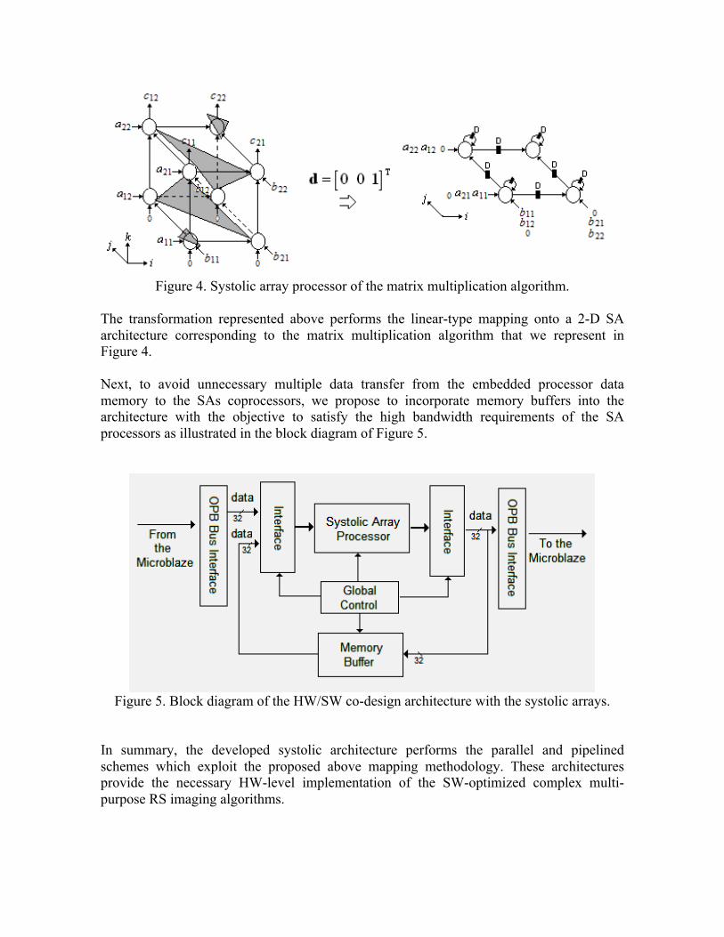
Figure 4. Systolic array processor of the matrix multiplication algorithm.
The transformation represented above performs the linear-type mapping onto a 2-D SA architecture corresponding to the matrix multiplication algorithm that we represent in Figure 4. Next, to avoid unnecessary multiple data transfer from the embedded processor data memory to the SAs coprocessors, we propose to incorporate memory buffers into the architecture with the objective to satisfy the high bandwidth requirements of the SA processors as illustrated in the block diagram of Figure 5.
Figure 5. Block diagram of the HW/SW co-design architecture with the systolic arrays.
In summary, the developed systolic architecture performs the parallel and pipelined schemes which exploit the proposed above mapping methodology. These architectures provide the necessary HW-level implementation of the SW-optimized complex multi-purpose RS imaging algorithms.
5. SIMULATIONS AND PERFORMANCE ANALYSIS
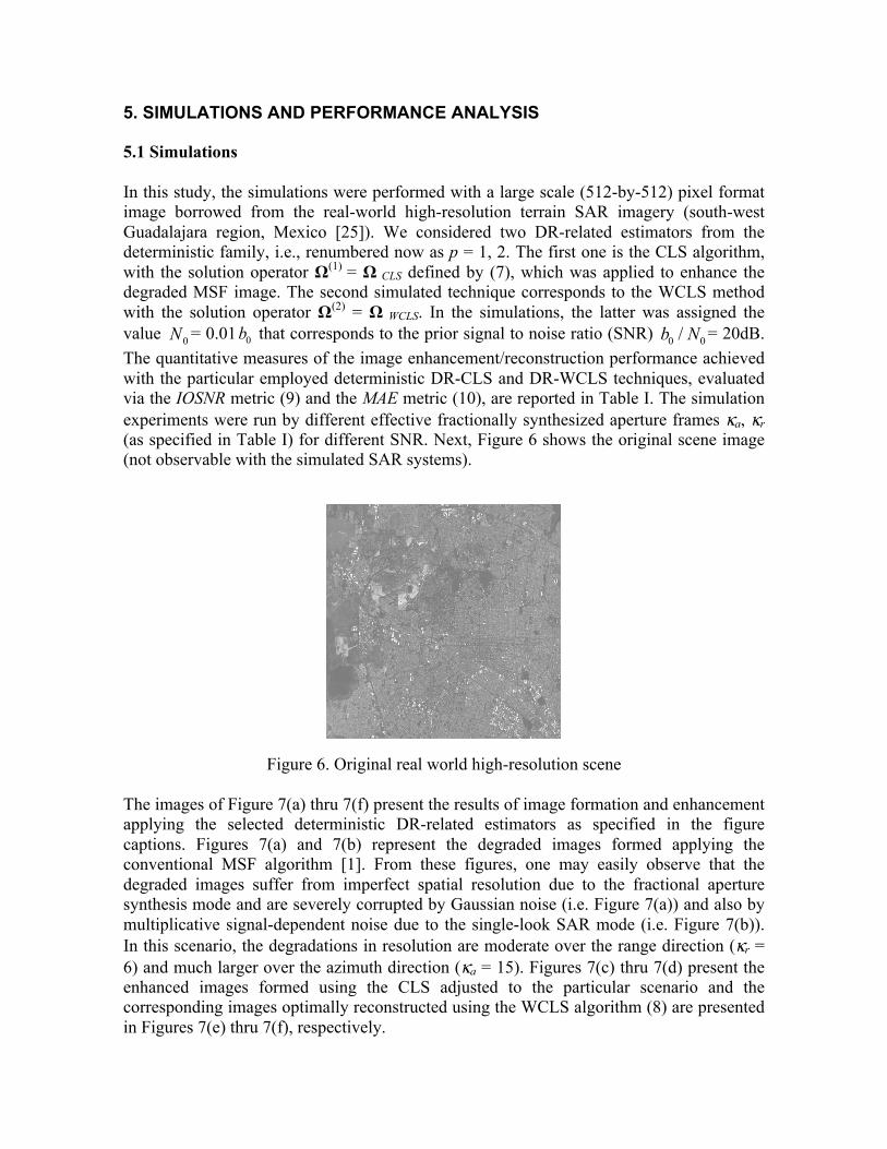
5.1 Simulations In this study, the simulations were performed with a large scale (512-by-512) pixel format image borrowed from the real-world high-resolution terrain SAR imagery (south-west Guadalajara region, Mexico [25]). We considered two DR-related estimators from the deterministic family, i.e., renumbered now as p = 1, 2. The first one is the CLS algorithm, with the solution operator Ω(1) = Ω CLS defined by (7), which was applied to enhance the degraded MSF image. The second simulated technique corresponds to the WCLS method with the solution operator Ω(2) = Ω WCLS. In the simulations, the latter was assigned the value 0N = 0.01 0b that corresponds to the prior signal to noise ratio (SNR) 0 0/b N = 20dB. The quantitative measures of the image enhancement/reconstruction performance achieved with the particular employed deterministic DR-CLS and DR-WCLS techniques, evaluated via the IOSNR metric (9) and the MAE metric (10), are reported in Table I. The simulation experiments were run by different effective fractionally synthesized aperture frames κa, κr (as specified in Table I) for different SNR. Next, Figure 6 shows the original scene image (not observable with the simulated SAR systems).
Figure 6. Original real world high-resolution scene The images of Figure 7(a) thru 7(f) present the results of image formation and enhancement applying the selected deterministic DR-related estimators as specified in the figure captions. Figures 7(a) and 7(b) represent the degraded images formed applying the conventional MSF algorithm [1]. From these figures, one may easily observe that the degraded images suffer from imperfect spatial resolution due to the fractional aperture synthesis mode and are severely corrupted by Gaussian noise (i.e. Figure 7(a)) and also by multiplicative signal-dependent noise due to the single-look SAR mode (i.e. Figure 7(b)). In this scenario, the degradations in resolution are moderate over the range direction (κr = 6) and much larger over the azimuth direction (κa = 15). Figures 7(c) thru 7(d) present the enhanced images formed using the CLS adjusted to the particular scenario and the corresponding images optimally reconstructed using the WCLS algorithm (8) are presented in Figures 7(e) thru 7(f), respectively.

a) b)
c) d)
e) f)
Figure 7. Simulation results: (a) degraded SAR scene image formed applying the MSF method corrupted by Gaussian noise [fractional SAR parameters: κr = 6 pixels, κa = 15 pixels; SNR = 20 dB]; (b) degraded SAR scene image formed applying the MSF method corrupted by Composite noise [fractional SAR parameters: κr = 6 pixels, κa = 15 pixels; SNR = 20 dB]; (c) image reconstructed applying the CLS algorithm for the degraded image with Gaussian noise; (d) image reconstructed applying the CLS algorithm for the degraded image with Composite noise; (e) image reconstructed applying the WCLS algorithm for the degraded image with Gaussian noise; (f) image reconstructed applying the WCLS algorithm for the degraded image with Composite noise.

Table I and Table II report the quantitative performances evaluated via two quality metrics (9) and (10) gained with the specified above robust deterministic DR-related SSP estimators (p = 1, 2). Table I. IOSNR values provided with the selected simulated DR-related methods, p = 1, 2.
SNR (dB)
IOSNR(p); p = 1,2 SCENARIO
(with Gaussian noise): κr = 6, κa = 15
SCENARIO (with Composite noise):
κr = 6, κa = 15 CLS WCLS CLS WCLS
5 3.03 3.82 3.48 3.59 10 4.36 5.13 4.13 4.41 15 5.52 6.07 5.46 5.92 20 6.84 8.73 5.78 7.21
Table II. MAE values provided with the selected simulated DR-related methods, p = 1, 2.
SNR (dB)
MAE(p); p = 1,2 SCENARIO
(with Gaussian noise): κr = 6, κa = 15
SCENARIO (with Composite noise):
κr = 6, κa = 15 CLS WCLS CLS WCLS
5 18.09 15.40 18.72 17.38 10 15.35 14.68 18.13 16.81 15 13.67 12.94 16.31 13.51 20 12.53 11.73 15.35 12.40
From the analysis of the simulation results, one may deduce that, the WCLS method over-performs the robust CLS in all simulated scenarios. The higher values of IOSNR as well as lower values of MAE were obtained with the robust deterministic DR-related estimators. Note that IOSNR (9) is basically a square-type error metric; thus, it does not qualify quantitatively the “delicate” visual features in the reconstructed images, hence, small differences in the corresponding IOSNRs reported in Table I. Also, the enhanced deterministic DR estimators manifest the higher IOSNRs and lower MAEs in the case of higher SNR (see Table II for MAE metrics). 5.2 HW Performance Analysis In this section, we complete our study with the comparative performance analysis of the proposed coprocessors for performing the reconstructive matrix operations of the CLS/WCLS algorithms, correspondingly. The synthesis metrics related to the implementation of the proposed SA for the reconstructive SP matrix multiplication operation are summarized in Table III and table IV. These metrics specify the area and time behavior of the selected hardware core.

Table III. Synthesis Metrics Area of the SA
Logic Utilization* Slice Registers, Flip Flops and Latches 6% LUTs, Logic, Shift Reg. and Dual-RAMs 5% BUFGs 8% DSP48 15% *The reference area is Xilinx Virtex-4 XC4VSX35-10ff668.
In Table III, we report the synthesis results evaluated for different metrics that are indicative of the efficiency of the proposed SA architecture. The exemplified test case of a 4×4 data matrix was considered. In Figure 8, we report the resource utilization of the proposed systolic hardware architecture designs for different numbers of processors elements (PEs).
Figure 8. Resource utilization varying the number of PEs.
Next, the overall time performance gain achieved with the proposed approach are reported in Table IV.
Table IV. Time Performance *Time Performance of the SA
Maximum Pin delay: 8.69ns Average connection delay on the 10 worst nets: 8.35 ns Maximum Frequency 115.3 MHz
*The reference system clock corresponds to the Xilinx Virtex-4 XC4VSX35-10ff668. With the n×n matrix-matrix multiplication systolic architecture developed in this study, the most time consuming operations required only 3n-2 clock cycles and the area occupied 386 slices for data precision of 32-b (e.g., considering the same n=4 test case). Other alternative implementations for systolic matrix multiplication were presented in [26]−[28]. In [26], the systolic matrix multiplication design occupied an area of 110 slices (i.e., data precision of 8-b) with the corresponding processing time of n2+3n+2 clock cycles. Mencer et al. in [27] presented the matrix multiplication architecture with an area performance of 954 slices for data precision of 8-b. An alternative matrix multiplication systolic architecture was also proposed in [28], which approached a total time of n2+2n clock cycles and 54,500 slices for the data precision of 64-b. As it is easy to deduce from the area-time comparative analysis

with all those alternatives implementations, the proposed systolic architectures for performing the matrix multiplication manifest the best area-time trade-off performance. Last, we compared the required processing time for two different implementation techniques as reported in Table V. In the first case, the reference deterministic DR procedure for the CLS and WCLS algorithms were implemented in the conventional MATLAB software in a personal computer (PC) running at 1.73GHz with a Pentium (M) processor and 1GB of RAM memory and in the second case, the same DR-related algorithms were implemented using the proposed FPGA based HW/SW co-design architecture (partitioning the Matlab application in SW and HW functions) employed in the Xilinx FPGA XC4VSX35-10ff668.
TABLE IV. Comparative Processing Time Study
Method Processing Time [secs] CLS WCLS
Reference PC-based Deterministic Descriptive Regularization 20.3 20.7
Proposed HW/SW Co-design 3.12 3.26 Analyzing the reported results one may deduce the following. FPGA based HW/SW co-design architecture manifests the (near) real time high-resolution reconstruction of the RS imagery. The implementation of the proposed HW/SW co-design architecture helps to reduce the overall processing time. Particularly, the proposed implementation of the deterministic DR WCLS algorithm with systolic arrays takes only 3.26 seconds for the image reconstruction. This new architecture implementation reduces the overall processing time approximately 6 times less than the reference implementation MATLAB-PC-based form the DR-related algorithm. 6. CONCLUSION In this paper, we have proposed the aggregation of the deterministic descriptive regularization and the HW/SW co-design methods particularly adapted for the enhancement/reconstruction of RS imagery. The unified deterministic DR-HW/SW co-design approach using efficient hardware systolic arrays as coprocessors have achieved the (near) real time RS requirements. At the algorithmic level, we present the quantitative performances gained via the proposed quality metrics of the unified deterministic DR-HW/SW co-design approach using the corresponding computational recipes. The processing time gain of the unified algorithmic (software-level) and systematic (hardware-level) co-design approach was achieved via partitioning all the important functions related to the specific problem into hardware units (i.e. systolic arrays co-processors) and software application in the embedded processor, i.e. the processing time of the deterministic DR-related CLS/WCLS algorithms were significantly reduced up to six times of the overall computation time. We do believe that pursuing the addressed HW/SW co-design paradigm one could approach definitely the (near) real time RS image processing requirements while performing the post-processing of the large-scale real-world RS imagery attaining the enhancement/reconstruction performance gains close to the limiting bounds.

REFERENCES [1] F.M. Henderson and A. V. Lewis, Principles and Applications of Imaging Radar,
Manual of Remote Sensing, 3d ed., vol. 3, John Willey and Sons Inc., New York, NY, 1998.
[2] H.H. Barrett and K.J. Myers, Foundations of Image Science, New York: Willey, 2004. [3] Ponomaryov V. I. : Real-time 2D–3D filtering using order statistics based algorithms.
Journal Real-Time Image Processing, 1:173–194, (2007). [4] Yang, C. T.; Chang, C. L.; Hung C. C. and Wu F.: “Using a Beowulf cluster for a
remote sensing application”, 22nd Asian Conference on Remote Sensing, 2001. [5] Plaza, A. and Plaza, J.: “Parallel morphological classification of hyperspectral imagery
using extended opening and closing by reconstruction operations”, 2008 IEEE International Geoscience & Remote Sensing Symposium (IGARSS2008), July 6-11, 2008.
[6] A. Castillo, Y. V. Shkvarko, D. Torres and H.M. Perez, “Convex regularization-based hardware/software co-design for real-time enhancement of remote sensing imagery,” Int. Journal of Real Time Image Processing, Edit. Springer, 2008.
[7] Greco, J.; Cieslewski, G.; Jacobs, A.; Troxel, I.A.; George, A.D., Hardware/software interface for high-performance space computing with FPGA coprocessors, Aerospace Conference, 2006 IEEE , pp. 10-25, 4-11, March 2006.
[8] Kung, S.Y., VLSI Array Processors, Prentice Hall, 1988. [9] Kung, H.T., Leiserson, C.E., “Systolic Arrays (for VLSI)”, Sparse Matrix Proceedings,
pp. 256-282, (1978). [10] Lo, S. C. and Jean, S. N.: Mapping Algorithms to VLSI Array Processors, International
Conference on Acoustics, Speech, and Signal Processing, 1988. [11] Shkvarko, Y.V.: "Estimation of wavefield power distribution in the remotely sensed
environment: Bayesian maximum entropy approach", IEEE Transactions on Signal Processing, vol. 50, No. 9, pp. 2333-2346, 2002.
[12] Shkvarko, Y.V., Perez Meana, H.M., and Castillo Atoche, A.: Enhanced radar imaging in uncertain environment: A descriptive experiment design regularization paradigm –Accepted for publication, Intern. Journal of Navigation and Observation, vol. 2008, Article ID 810816, pp. 1-11, 2008.
[13] Shkvarko, Y.V.: “Unifying Regularization and Bayesian Estimation Methods for Enhanced Imaging with Remotely Sensed Data. Part I – Theory”. IEEE Transactions on Geoscience and Remote Sensing. Vol. 42. IEEE, 923-931, 2004.
[14] Shkvarko, Y.V.: “Unifying Regularization and Bayesian Estimation Methods for Enhanced Imaging with Remotely Sensed Data. Part II – Implementation and Performance Issues”. IEEE Transactions on Geoscience and Remote Sensing. Vol. 42. IEEE, 932-940, 2004.
[15] Wehner, D.R.: High-Resolution Radar. 2nd edn. Artech |House, Boston, 1994. [16] H.H. Barrett and K.J. Myers, Foundations of Image Science, New York: Willey, 2004 [17] Z. Navabi, Embedded Core Design with FPGAs. McGraw-Hill Professional, 2006. [18] M.López-Vallejo and J. C. López, On the hardware-software partitioning problem:
System modeling and partitioning techniques. ACM Trans. Des. Autom. Electron. Syst., vol. 8, issue. 3, pp. 269-297, Jul. 2003.
[19] IBM Microelectronics division, On chip Peripheral Bus: Architecture Specifications, IBM, version 2.1, 2001.

[20] J. S. Lee, “Speckle suppression and analysis for synthetic aperture radar images”, Optical Engineering, vol. 25, no. 5, pp. 636-643, 1986.
[21] V. I. Ponomaryov. : Real-time 2D–3D filtering using order statistics based algorithms. Journal Real-Time Image Processing, 1:173–194, 2007.
[22] Wei Jin; Zhang, C.N.; Hua Li, "Mapping multiple algorithms into a reconfigurable systolic array," Canadian Conference on Electrical and Computer Engineering (CCECE2008), pp.001187-001192, May 2008.
[23] J. Pan, T. Zhou, Y. Han and M. Jiang, “Variable Weighted Ordered Subset Image Reconstruction Algorithm”, International Journal of Biomedical Imaging Volume 2006 (2006), Article ID 10398, 7 pages, doi:10.1155/IJBI/2006/10398.
[24] Y. Shkvarko and I. E. Villalon-Turrubiates, “Real-Time Reconstruction of Remote Sensing Imagery: Aggregation of Robust Regularization with Neural Computing”, Proceedings of the 17th International Association for Mathematics and Computers in Simulation World Congress (IMACS), Paris France, 2005.
[25] Space imaging in: http://www.spaceimaging.com. GeoEye Inc., 2008. [26] Zicari, P.; Corsonello, P.; Perri, S; Cocorullo, G.: A matrix product accelerator for field
programmable systems on chip, Microprocessors and Microsystems, Volume 32, Issue 2, pp. 53-67, 2008.
[27] O. Mencer, M. Morf, M. Flynn, “High performance FPGA design for adaptive computing,” IEEE Symposium on Field- Programmable Custom Computing Machines, Napa Valley, California, p.p. 167-169, April 1998.
[28] L. Zhuo, V.K. Prasanna, “Scalable and modular algorithms for floating-point matrix multiplication on FPGAs,” Parallel and Distributed Processing Techniques and Applications, p.p. 328–332, 2003.