Diseño e Implementacion del Software de Control para … · Resumen Durante el desarrollo del...
163
DISEÑO E IMPLEMENTACIÓN DEL SOFTWARE DE CONTROL PARA UN CENTRO DE MECANIZADO CNC PEDRO FERNANDO GIFFUNI SALAZAR Monografía para optar al título de Ingeniero Mecánico Director FERNANDO MEJÍA UMAÑA Ingeniero Mecánico UNIVERSIDAD NACIONAL DE COLOMBIA FACULTAD DE INGENIERÍA DEPARTAMENTO DE INGENIERÍA MECÁNICA SANTAFÉ DE BOGOTÁ, D. C. 1996
Transcript of Diseño e Implementacion del Software de Control para … · Resumen Durante el desarrollo del...
DISEÑO E IMPLEMENTACIÓN DEL SOFTWARE DE CONTROL PARA UN
CENTRO DE MECANIZADO CNC
PEDRO FERNANDO GIFFUNI SALAZAR
Monografía para optar al título de
Ingeniero Mecánico
Director
FERNANDO MEJÍA UMAÑA
Ingeniero Mecánico
UNIVERSIDAD NACIONAL DE COLOMBIA
FACULTAD DE INGENIERÍA
DEPARTAMENTO DE INGENIERÍA MECÁNICA
SANTAFÉ DE BOGOTÁ, D. C.
1996

AGRADECIMIENTOS
El autor expresa sus agradecimientos a:
ANDRES DIAZ GONZALEZ, Ingeniero electrónico y Profesor del Departamento
de Fisica de la Universidad Nacional de Colombia.
FERNANDO MEJIA UMAÑA, Ingeniero Mecánico y Director de la Investigación.

ii
CONTENIDO
pág.
INTRODUCCIÓN 11
1. CONFORMACIÓN DE UN SISTEMA DE
MANUFACTURA AUTOMATIZADA 16
1.1 EL CONTROL NUMÉRICO POR COMPUTADOR 16
1.2 ECONOMÍA EN LA MANUFACTURA 18
1.3 ESQUEMA CLÁSICO 21
1.4 ESTRUCTURA CIM 23
1.5 CONTROL NUMÉRICO DIRECTO: DNC 27
iii
pág.
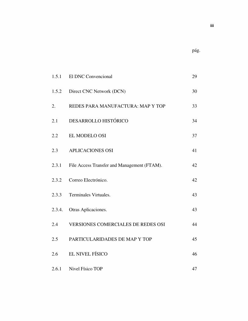
1.5.1 El DNC Convencional 29
1.5.2 Direct CNC Network (DCN) 30
2. REDES PARA MANUFACTURA: MAP Y TOP 33
2.1 DESARROLLO HISTÓRICO 34
2.2 EL MODELO OSI 37
2.3 APLICACIONES OSI 41
2.3.1 File Access Transfer and Management (FTAM). 42
2.3.2 Correo Electrónico. 42
2.3.3 Terminales Virtuales. 43
2.3.4. Otras Aplicaciones. 43
2.4 VERSIONES COMERCIALES DE REDES OSI 44
2.5 PARTICULARIDADES DE MAP Y TOP 45
2.6 EL NIVEL FÍSICO 46
2.6.1 Nivel Físico TOP 47

iv
pág.
2.6.2 Nivel Físico MAP 48
2.7 SERVICIOS MAP Y TOP 49
2.8 EL NIVEL DE APLICACIÓN EN MAP 51
2.8.1 Aplicaciones MAP 52
2.8.2 Manufacturing Message Specification (MMS) 54
3. MODELO DEL CONTROLADOR NUMÉRICO 59
3.1 LA UNIDAD DE EJECUCIÓN 60
3.2 LA UNIDAD CONSOLA 62
4. PROGRAMACIÓN DE UNA MÁQUINA HERRAMIENTA
CNC 64
4.1 CONTROLES 64
4.2 INSTRUCCIONES OPERACIONALES 66
4.3 INFORMACIÓN DE PROGRAMACIÓN 70
4.3.1 Información Geométrica 70
v
pág.
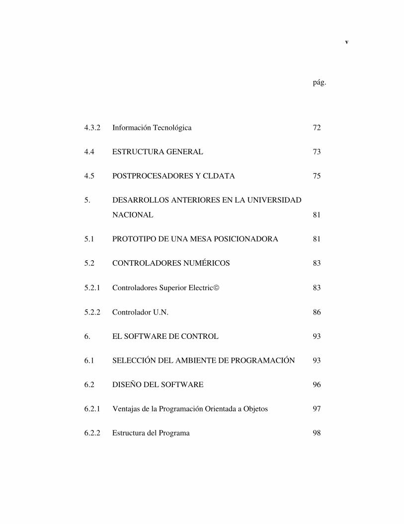
4.3.2 Información Tecnológica 72
4.4 ESTRUCTURA GENERAL 73
4.5 POSTPROCESADORES Y CLDATA 75
5. DESARROLLOS ANTERIORES EN LA UNIVERSIDAD
NACIONAL 81
5.1 PROTOTIPO DE UNA MESA POSICIONADORA 81
5.2 CONTROLADORES NUMÉRICOS 83
5.2.1 Controladores Superior Electric© 83
5.2.2 Controlador U.N. 86
6. EL SOFTWARE DE CONTROL 93
6.1 SELECCIÓN DEL AMBIENTE DE PROGRAMACIÓN 93
6.2 DISEÑO DEL SOFTWARE 96
6.2.1 Ventajas de la Programación Orientada a Objetos 97
6.2.2 Estructura del Programa 98

vi
pág.
6.2.3 Consideraciones Técnicas 99
6.3 EL CONTROLADOR DE DISPOSITIVOS 100
6.4 EL CONTROLADOR DE EVENTOS 104
6.5 LA CONSOLA 105
6.6 FUNCIONAMIENTO DEL PROGRAMA 107
7. CONCLUSIONES 109
REFERENCIAS BIBLIOGRÁFICAS 114
ANEXOS 116

vii
LISTA DE FIGURAS
pág.
Figura 1. Modelo Jerárquico de una Instalación de
Manufactura Automatizada. 25
Figura 2. Estructura Común de una Implementación
CNC. 28
Figura 3. Variantes de Sistemas DNC. 29
Figura 4. Comparación entre Dos Estrategias de Control
Numérico. 31
Figura 5. Configuración Típica MAP-TOP. 36
Figura 6. El Nivel de Aplicaciones en MAP. 54
viii
pág.
Figura 7. Esquema de un Dispositivo de Manufactura
Virtual (VMD). 55
Figura 8. Modelo Moreaux de un Controlador Numérico. 61
Figura 9. Ejemplo de una Configuración de Hardware
Generalizada. 66
Figura 10. Jerarquía de las Instrucciones Operativas. 67
Figura 11. CLDATA Convencional vs. BCL. 79
Figura 12. Mesa Posicionadora del Convenio SENA-UN. 82
Figura 13. Controlador MX 2000. 84
Figura 14. Arreglo de Controladores Superior Electric. 85
Figura 15. Esquema de Funcionamiento del Controlador U. N. 87
Figura 16. Interrupción con el Protocolo Traducido. 88
Figura 17. Configuración Usada en el Controlador U. N. 89
Figura 18. Listado de ComDev.h. 101
Figura 19. Cuadro de Diálogo para Configurar el Puerto. 104

ix
Figura 20. Imagen del Menu de Edición en la Aplicación. 106
Figura 21. Imagen del Programa Final en el Ambiente Gráfico
de Windows 95™. 107
x
LISTA DE TABLAS
pág.
Tabla 1. Representación de los Niveles OSI. 40
Tabla 2. Suites de Protocolo MAP y TOP. 50
Tabla 3. Instrucciones Operacionales Comunes. 69
Tabla 4. Códigos G Comúnmente Usados. 71
Tabla 5. Algunos Códigos M. 73

xi
Resumen
Durante el desarrollo del proyecto se investigaron las estrategias adecuadas para obte-
ner una estructura de control automatizado en una empresa metalmecánica. Con este
fin se obtuvieron modelos en bloques de un controlador numérico genérico y del mane-
jo de la información en una planta industrial, y se identificó la necesidad de distribuir la
inteligencia de la planta donde ésta se requiere.
Se investigaron diversos avances tecnológicos como el control numérico directo y las
redes industriales, que pueden ser decisivos en el momento de seleccionar la estrategia
de manufactura que usará un planta industrial competitiva.
Como resultado de la investigación se utilizó la programación orientada a objetos co-
mo una herramienta adecuada para implementar un programa de computador capaz de
controlar diversos dispositivos de manufactura.
Al final se incluye el programa con todo su código fuente y una copia del informe en
formato postscript.
INTRODUCCIÓN
En la historia de la humanidad hay periodos de grandes cambios en que se modifican
los rumbos de las generaciones: la revolución industrial y la revolución electrónica son
dos momentos históricos que presentan esa característica y que han impulsado el desa-
rrollo tecnológico y el avance de la ingeniería. Siguiendo el espíritu de estas grandes
revoluciones hay una tendencia creciente por incorporar nuevas tecnologías al proceso
de producción con la esperanza de tener algún día un proceso en que la única interac-
ción del ser humano con su fábrica sea la de diseñar.
Por supuesto, la revolución industrial y la electrónica no son las primeras ni las últimas
expresiones de cambio en la humanidad: hoy en día se vive en el mundo una revolu-
ción informática, donde no sólo prima la capacidad de acción sino la oportunidad de la
información.
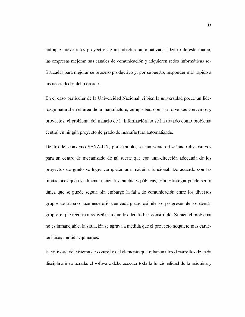
Entendiendo que todo proceso moderno de manufactura involucra un problema de
transporte y procesamiento de información, es fácil comprender la necesidad de dar un
13
enfoque nuevo a los proyectos de manufactura automatizada. Dentro de este marco,
las empresas mejoran sus canales de comunicación y adquieren redes informáticas so-
fisticadas para mejorar su proceso productivo y, por supuesto, responder mas rápido a
las necesidades del mercado.
En el caso particular de la Universidad Nacional, si bien la universidad posee un lide-
razgo natural en el área de la manufactura, comprobado por sus diversos convenios y
proyectos, el problema del manejo de la información no se ha tratado como problema
central en ningún proyecto de grado de manufactura automatizada.
Dentro del convenio SENA-UN, por ejemplo, se han venido diseñando dispositivos
para un centro de mecanizado de tal suerte que con una dirección adecuada de los
proyectos de grado se logre completar una máquina funcional. De acuerdo con las
limitaciones que usualmente tienen las entidades públicas, esta estrategia puede ser la
única que se puede seguir, sin embargo la falta de comunicación entre los diversos
grupos de trabajo hace necesario que cada grupo asimile los progresos de los demás
grupos o que recurra a rediseñar lo que los demás han construido. Si bien el problema
no es inmanejable, la situación se agrava a medida que el proyecto adquiere más carac-
terísticas multidisciplinarias.
El software del sistema de control es el elemento que relaciona los desarrollos de cada
disciplina involucrada: el software debe acceder toda la funcionalidad de la máquina y
14
hacerla disponible al usuario final. Inicialmente se pensó que el problema del software
debería ser solucionado exclusivamente por ingenieros de sistemas, sin embargo la
aceptación que tal software pueda tener a largo plazo depende de la facilidad con éste
software se adapte a la tecnología propia del sector metalmecánico, por lo cual se ha
entendido que la estructura inicial debe ser propuesta por un ingeniero mecánico.
El objetivo de este proyecto de grado es el de plantear un modelo del software de alto
nivel que gobierne un centro de mecanizado genérico, y de esta forma aporte linea-
mientos para futuros desarrollos en la Universidad Nacional. Para cumplir este objeti-
vo esencial, se estudiaron las diversas tecnologías utilizadas en los países industrializa-
dos de tal forma que se mantuvieran las normas técnicas vigentes y obtener una solu-
ción compatible con la tecnología externa. Un objetivo secundario, el diseño de un
prototipo del software para controlar la mesa posicionadora XY, constituye una guía
importante para las etapas posteriores del proceso investigativo.
En el primer capítulo, Conformación de un Sistema de Manufactura Automatizada, se
analizan diversos aspectos económicos del proceso de manufactura y se presenta un
modelo de distribución de planta que permite estandarizar las comunicaciones en los
procesos de manufactura.
15
El segundo capítulo recoge el espíritu del primero y trata el tema de las redes indus-
triales. El tema de este capítulo es una aporte completamente nuevo que se deriva de
la revolución informática actual.
El tercer capítulo, Modelo del Controlador Numérico, presenta los fundamentos
esenciales para la construcción del software de manufactura: en él se presenta un mo-
delo con las características de un controlador numérico genérico y su software de
control.
El cuarto capitulo, Programación de una Máquina Herramienta CNC, presenta todos
los factores que se deben tener en cuenta para interactuar con una máquina de control
numérico. Toda la información de este capitulo está normalizada, lo cual facilita la mi-
sión de unificar conceptos frente al diseño actual.
En el último capitulo se presenta el software que se diseñó, junto con una descripción
breve de las herramientas utilizadas. Más importante que el programa mismo, se pre-
sentan los criterios de diseño y se presenta un modelo que se ajusta a las necesidades
del problema estudiado.
Los tres anexos merecen una presentación especial. Aunque estos documentos fueron
modificados para mantener un formato estándar, se respetaron algunos aspectos de los
documentos originales como el espaciado.

16
El anexo A es la norma básica que se sigue internacionalmente para adecuar redes in-
dustriales a las redes ordinarias que usan TCP-IP. El documento es de libre distribu-
ción.
El anexo B es un documento que describe el protocolo MMS. Este documento, de di-
fícil consecución, sirve de guía para un futuro desarrollador en el momento de utilizar
una red de comunicación industrial. El documento es de libre distribución siempre que
su contenido sea respetado integralmente y no se use para fines comerciales.
El anexo C presenta el conjunto de instrucciones de una máquina herramienta dispo-
nible comercialmente: es importante en cuanto presenta un protocolo típico basado en
las normas ISO. Estas normas se obtuvieron durante un curso en el SENA.
CONFORMACIÓN DE UN SISTEMA DE MANUFACTURA AUTOMATIZADA
1.1 EL CONTROL NUMÉRICO POR COMPUTADOR
El desarrollo de la electrónica industrial y de los computadores en los últimos años ha
traído consigo nuevas opciones en los métodos de manufactura tradicional. El control
numérico por computador (CNC), en particular, pretende aprovechar el manejo numé-
rico avanzado de los computadores para automatizar una buena parte de la manufactu-
ra moderna. Tales desarrollos han cambiado la forma misma en que se concibe el pro-
ceso de producción metalmecánico, haciendo el proceso cada vez más automático.
En la actualidad se consiguen comercialmente máquinas mandrinadoras, cepilladores,
robots industriales, rectificadoras, fresadoras, prensas, tornos, cizallas taladradoras y
plegadoras de control numérico. Debido a su alto costo estas máquinas se usan para
una labor específica; sin embargo, por su flexibilidad, llama a la atención el creciente
uso de los centros de mecanizado. Un centro de mecanizado es una máquina que po-
18
see un gran número de herramientas y un cambiador automático, de ésta forma se
puede obtener una gran variedad de funciones en la misma máquina. Cambiar la confi-
guración de herramientas de una máquina CNC provee una habilidad para cambiar la
capacidad de producción.
Entre las ventajas de una máquina de control numérico se encuentran:
• Alta precisión y buenos terminados gracias al control automático del proceso. Se
reducen, además los tiempos muertos y se aumenta la velocidad de posicionamiento
de la máquina.
• Repetitividad de algoritmos que permiten la producción en serie de piezas: basta
recuperar un programa ya almacenado para poder fabricar una pieza particular.
• Independencia a errores del operario, especialmente en piezas que requerirían gran
concentración al ser fabricadas por otros medios.
Entre las desventajas se encuentran:
• El elevado costo del puesto de trabajo.
• Mayor dificultad al planear el trabajo debido a la dificultad en adaptar una máquina
a cualquier necesidad: el ser humano entiende el problema y plantea alternativas.
No hay, entonces, una metodología predeterminada que nos diga cuando o que caso es
mejor adoptar un sistema CNC. La tecnología actual presenta gran dinamismo: no solo

19
aparecen y desaparecen nuevas tecnologías constantemente, sino que las condiciones
del mercado varían, siendo necesario mantenerse al tanto de los nuevos desarrollos. La
estrategia a seguir debe ser la de aprovechar la flexibilidad que puede dar el software
para resolver los problemas que tradicionalmente tienen las máquinas herramientas.
Manufactura flexible implica capacidad flexible, y ésta se obtiene con mano de obra
flexible, personal experto en diversas áreas, o con maquinado flexible, máquina con
variedad de herramientas.
No siempre utilizar una máquina CNC es la solución óptima para una empresa: la ex-
periencia de un operario es un valuarte muy importante que no es incompatible con las
nuevas tecnologías. La tendencia actual indica que en materia de automatización, una
empresa ya conformada obtiene mejores resultados al mejorar primero su planeamien-
to de operaciones y su gestión de producción.
1.2 ECONOMÍA EN LA MANUFACTURA
En los últimos años se ha presentado una creciente competencia entre las industrias
norteamericanas, europeas y japonesas. El caso del Japón llama la atención entre los
economistas por tratarse de un país pobre en recursos naturales que perdió una guerra

20
mundial. El éxito inicial de los productos japoneses en los diversos mercados del se
explicó por una combinación entre un mercadeo eficiente y una mano de obra barata,
sin embargo los sueldos japoneses eventualmente pasaron los sueldos norteamericanos
por lo que esta explicación perdió vigencia. Una explicación posterior se dió en la efi-
ciencia de los procesos productivos, pero ni siquiera los procesos norteamericanos de
máxima eficiencia, denominados Advanced Manufacturing Tecnology (AMT), han lo-
grado productos con el nivel de aceptación en el consumidor que tienen los productos
japoneses. Hoy en día1 se considera que la supremacía japonesa no se debe a que sus
procesos sean mas eficientes que los de los competidores sino que simplemente son
más eficaces.
En un estudio sobre el ámbito colombiano, realizado por Oscar Marulanda y Camilo
Rubio2, sobre la asimilación de nuevas tecnologias en el sector metalmecánico, se pre-
sentan estadísticas oficiales del DANE y se estima que entre 1968, año en que llegó la
primera maquina herramienta de control numérico (MHCN), y 1982 se habían incor-
porado menos de 50 MHCN en el país. La baja adquisición es, según los autores, de-
bida al bajo costo de la mano de obra en el país y la estructura industrial. Una apertura
económica tiene una influencia fuerte, especialmente en el sector de las autopartes, y
se presenta como un arma de doble filo: por un lado se desestimula la producción na-
1 Ver Lowry, J. “Japan: a lead to follow?”, CADCAM International, 1988, 7, (12), pp 19-21.
2 Marulanda O. y C. Rubio. “Impacto de la tecnología microelectrónica en la industria metalmecánica de Co-lombia”. OFICEL, Bogotá (Informe de Investigación), 1983
21
cional debido al bajo costo que permiten los altos índices de producción en los países
industrializados, por otra parte facilita la entrada de nuevos fabricantes de MHCN, es-
pecialmente los fabricantes orientales que ofrecen maquinas pequeñas y relativamente
baratas, más acordes con lo requerido en las empresas nacionales medianas y grandes.
Existen varias estrategias de diseño para minimizar los costos de manufactura, aumen-
tando así la competitividad y las ganancias. Boothroyd3 plantea dos reglas básicas: di-
señar de tal manera que se usen tantos elementos normalizados como sea posible, y
minimizar la cantidad de mecanizado con el preformado de la pieza. Estas reglas po-
drían resumirse en un principio general: evitar mecanizar.
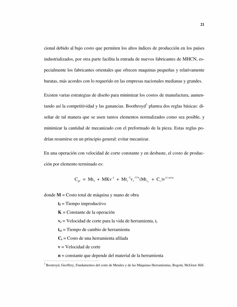
En una operación con velocidad de corte constante y en desbaste, el costo de produc-
ción por elemento terminado es:
C = Mt + MKv + Mt v (Mt + C )vpr I-1
r-1
r-1/ n
c t(1-n)/ n
t
donde M = Costo total de máquina y mano de obra
tI = Tiempo improductivo
K = Constante de la operación
vr = Velocidad de corte para la vida de herramienta, tr
tct = Tiempo de cambio de herramienta
Ct = Costo de una herramienta afilada
v = Velocidad de corte
n = constante que depende del material de la herramienta 3 Bootroyd, Geoffrey, Fundamentos del corte de Metales y de las Máquinas Herramientas, Bogotá, McGraw Hill.
22
En un centro de mecanizado se pretende optimizar cada uno de estos factores, espe-
cialmente el tiempo de cambio de herramienta tct, y el tiempo improductivo tI, para
obtener un mecanizado eficiente.
La mejora en velocidades de mecanizado, y en particular la eliminación de los tiempos
muertos son la clave para conseguir un proceso económicamente eficiente. Lógica-
mente, la eficiencia del proceso no garantiza el éxito económico pero marca la pauta
para aumentar la rentabilidad.
1.3 ESQUEMA CLÁSICO
La tecnología del control numérico por computador se mezcla con otras estrategias
diversas que tienden a lograr el esquema conocido como Computer Integrated Manu-
facturing (CIM). CIM es la participación coordinada de los computadores en todas las
fases de la manufactura. El objetivo final es lograr una infraestructura con el máximo
nivel de automatización en la que sea más sencillo pasar del diseño original a la pieza
fabricada.

23
Aunque las bondades del control numérico no requieren de ninguna otra tecnología o
de la aplicación de alguna estrategia de producción, este se ve fortalecido al aplicar di-
chos principios. Los resultados, por tanto, son mejores cuando las tecnologías moder-
nas se combinan con nuevas estrategias de producción. En empresas que no requieren
excesivo personal administrativo es más barato comenzar implementando las estrate-
gias de producción modernas, como JIT y Kanban, para después combinarlas con la
innovación tecnológica. El objetivo es aumentar la productividad y por tanto aumentar
las ganancias a través de la creciente automatización de los sistemas productivos co-
rrientes.
Es usual encontrar fábricas que usan tecnologías viejas que han sido reemplazadas
paulatinamente con tecnologías nuevas. En las plantas nuevas, este no es el caso ge-
neral; las maquinas herramientas tradicionales, aunque mas baratas, son reemplazadas
por máquinas mas especializadas y modernas. Por la flexibilidad de estas máquinas, y
su alto costo, es claro que se deben reducir los tiempos muertos para recuperar rápi-
damente la inversión inicial. En estos casos, la planeación de la producción es de gran
relevancia y antecede la decisión de adquirir el equipo.
En Colombia las redes industriales son tecnologías aún lejanas, por lo que se tiende a
hacer énfasis solo en la planeación de recursos de materiales. Dentro de las nuevas
tecnologías tenemos redes industriales, el diseño asistido por computador, la manufac-
24
tura asistida por computador, y las herramientas de planeación de la producción. Al-
gunas de estas tecnologías se han estabilizado, como es caso de Manufacturing Auto-
mated Protocol (MAP), mientras que otras, como el Computer Assisted Production
Planning (CAPP), están aún en una etapa de investigación.
1.4 ESTRUCTURA CIM
Para que CIM actúe como un sistema homogéneo es necesario que cada sector discre-
to de la industria tenga acceso a cualquier información que requiera. Una solución
sencilla a un problema tan complicado consistió en almacenar toda la información del
proceso en una sola base de datos centralizada que podría ser consultada por todos los
subsistemas de manufactura. Esta teoría resultó poco viable por las siguientes razones:
• Aún con la tecnología actual, se duda que una base de datos pueda almacenar todos
los detalles actualizados del proceso.
• De existir la base de datos, la respuesta sería muy lenta por la cantidad de procesos
e información involucrada.
25
• Cada función realizada por el subproceso requiere solo una pequeña porción de la
información disponible.
• La administración y el mantenimiento de tal sistema serían complejas e inmaneja-
bles.
La dificultad de implementar todas las funciones requeridas en un solo sistema y la ne-
cesidad de mantener el control del proceso cerca de donde éste se realiza han mostra-
do la necesidad de distribuir el sistema de información.
La calidad del sistema de comunicaciones es vital para el correcto desarrollo de una
estrategia CIM: una herramienta adecuada, pero no la única, es usar redes locales para
transmisión digital.
Las funciones realizadas por un sistema de información en un ambiente industrial se
pueden clasificar de acuerdo a un modelo jerárquico como el propuesto por el Natio-
nal Institute of Standards and Technology4, NIST, de los Estados Unidos5. En la ar-
quitectura propuesta hay cuatro componentes básicos: el control de los sistemas de
manufactura, la administración de la información distribuida, los sistemas de comuni-
caciones, y la interfaze con usuarios. De estos cuatro puntos, el más importante es el
4 El National Bureau of Standards (NBS), fue reemplazado posteriormente por NIST.
5 McLean C., Mitchell M. y Barkmeyer E. A Computer Arquitecture for Small-Batch Manufacturing, IEEESpectrum, n. 5, Mayo 1983

26
control de los sistemas de manufactura, ya que de este se derivan algunas característi-
cas en los demás.
En este modelo se ordenan los módulos de control de acuerdo a una jerarquía. Cada
control recibe comandos únicamente de una jerarquía superior, pero puede redireccio-
nar algunos comandos al nivel inmediatamente inferior. De esta manera, los procesos
se reciben en un nivel superior y se dividen en subpartes mas sencillas a medida que se
desciende en la jerarquía para realizar operaciones de bajo nivel.
El comportamiento de un sistema de manufactura debe ser adaptivo y determinístico;
por tanto la estructura de control será una jerarquía de controles realimentados que se
modelan e implementan como máquinas de estado. El sistema de control resultante es,
entonces, un procesador complejo de todas las entradas, salidas, estados, y transicio-
nes de estado de cada subsistema en el proceso de manufactura.
En todo caso se debe tener en cuenta un ciclo de control, es decir la variable tiempo,
que garantice que el subproceso mantenga su estado dentro de límites aceptables.
27
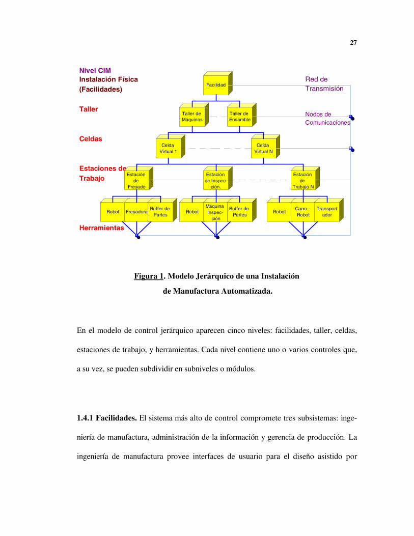
En el modelo de control jerárquico aparecen cinco niveles: facilidades, taller, celdas,
estaciones de trabajo, y herramientas. Cada nivel contiene uno o varios controles que,
a su vez, se pueden subdividir en subniveles o módulos.
1.4.1 Facilidades. El sistema más alto de control compromete tres subsistemas: inge-
niería de manufactura, administración de la información y gerencia de producción. La
ingeniería de manufactura provee interfaces de usuario para el diseño asistido por
Instalación Física(Facilidades)
Taller
Celdas
Estaciones deTrabajo
Herramientas
Red de Transmisión
Nodos deComunicaciones
Robot Fresadora
Estación de
Fresado
Buffer de Partes
Celda Virtual 1
Robot
Taller de Máquinas
Máquina Inspec-
ción
Estación de Inspec-
ción.
Facilidad
Buffer de Partes
Taller de Ensamble
Celda Virtual N
RobotCarro - Robot
Estación de
Trabajo N
Transportador
Nivel CIM
Figura 1. Modelo Jerárquico de una Instalación
de Manufactura Automatizada.

28
computador, al igual que la planeación de los procesos de producción. La administra-
ción de la información provee interfaces y soporte para inventarios, distribución de los
pedidos, y reabastecimiento. La gerencia de producción hace seguimiento de los pro-
yectos importantes e identifica la capacidad de producción y sus requerimientos o ex-
cesos. La información de planeación en este nivel se utiliza para dirigir el sistema de
control del taller en el siguiente nivel.
1.4.2 Taller. Este nivel es el responsable por el manejo en tiempo real de los recursos
y labores a través de dos módulos: gerencia de funciones y gerencia de recursos. El
primero programa las órdenes de trabajo, el mantenimiento de equipos, y los servicios
de soporte en taller. El segundo módulo asigna las estaciones de trabajo, las herra-
mientas y los materiales a la celdas de manufactura y los procesos específicos de pro-
ducción.
1.4.3 Celdas. Los controladores de este nivel controlan la secuencia de trabajo en
partes similares o ensamblajes, incluyendo manipulación de materiales y calibración. Al
definirse, en el nivel anterior, los materiales, recursos, y procesos necesarios, queda
configurada una celda virtual de manufactura. La celda se denomina “virtual” porque
en este caso no se trata de un agrupamiento físico específico en la planta, sino de un
29
agrupamiento lógico. Los módulos dentro de este nivel son de gran inteligencia, ya
que deben analizar la disponibilidad de recursos, reportar el progreso de los trabajos y
llevar registros de las labores realizadas en las estaciones de trabajo.
1.4.4 Estaciones de Trabajo. Este nivel dirige y coordina grupos de equipos dispo-
nibles en la planta. El controlador prepara la secuencia de trabajo en los equipos, te-
niendo en cuenta la preparación de la pieza, los procesos de corte, el desplazamiento
del material entre máquinas, la inspección y la limpieza.
1.4.5 Herramientas. Los controladores están conectados directamente a una variedad
de equipos que realizan todo el trabajo físico. Usualmente se encuentran robots, má-
quinas herramientas de control numérico, máquinas de medición, sistemas de distribu-
ción, y dispositivos de almacenamiento.
1.5 CONTROL NUMÉRICO DIRECTO: DNC

30
Los Programable Logic Controllers (PLC´s) y los controladores numéricos CNC son
herramientas que han estado presentes durante muchos años, y su permanencia depen-
de del nivel que alcance la tecnología de los microcomputadores. La tendencia crecien-
te es tener controladores numéricos tan poderosos que reemplacen los controladores
lógicos programables PLC, estos controladores pueden ser máquinas dedicadas, de
manera análoga a un PLC, o puede ser una tarjeta electrónica en una estación de traba-
jo.
El DNC, o control numérico directo, es una herramienta que ha ganado gran populari-
dad por el éxito que se ha tenido usando CAD/CAM para realizar contornos tridimen-
Controlador Numérico
Máquina Herramienta
CN
Almacenamiento
Secundario
Consola Operario
Producto Terminado
CAD/CAM
CAPP
Producción
Figura 2. Estructura Común de una
Implementación CNC

31
sionales. Si bien los programas que se generan a partir de las trayectorias de los pro-
gramas CAD/CAM son inmensos, la memoria de un controlador numérico es muy pe-
queña y se requiere un método de control que permita la alimentación progresiva de la
información.
1.5.1 EL DNC CONVENCIONAL
El DNC consta de tres componentes: el control numérico en la máquina herramienta,
el computador, y la línea serial que los conecta.
(a) DNC Mínimo. (b) DNC con Red Local.
Figura 3. Variantes de Sistemas DNC.
32
Aunque estos tres componentes son la esencia del DNC, el ambiente típico de desarro-
llo tiene muchos otros factores: el transporte de la información entre el centro
CAD/CAM y el computador del DNC puede ser un factor importante a considerar.
Aunque el mensajero ha sido el sistema tradicional de transportar la información, los
ambientes de alta producción adoptaron redes de área local (LANs) de alta velocidad
para transportar esta información.
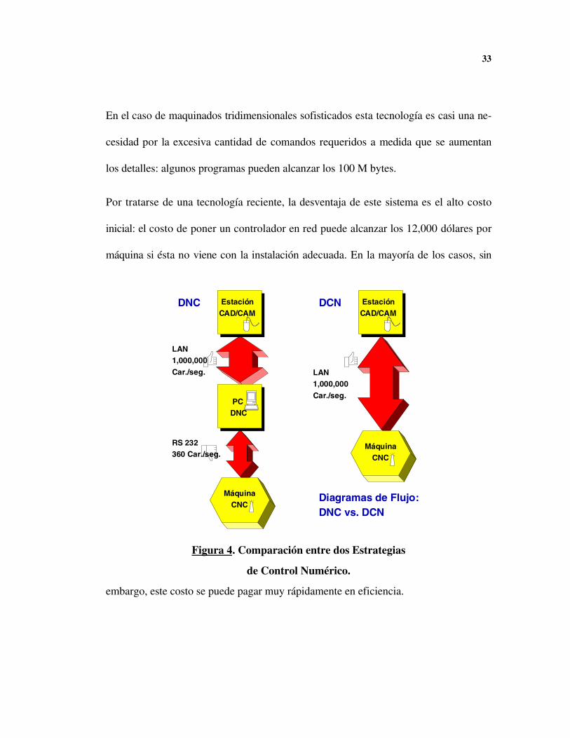
1.5.2 DIRECT CNC NETWORK (DCN)
Un cable serial convencional transporta la información a una velocidad de 960 caracte-
res por segundo, mientras una red local transporta fácilmente un millón de caracteres
por segundo. Esta diferencia, con mejora de casi mil veces en el transporte de la in-
formación, hace pensar en aprovechar ese ancho de banda en otras aplicaciones
(regulación del proceso, información de audio, vídeo, etc..) pero también sugiere una
perspectiva más interesante: la conexión directa del controlador a la red y la subse-
cuente desaparición de las etapas intermedias de transporte.
33
En el caso de maquinados tridimensionales sofisticados esta tecnología es casi una ne-
cesidad por la excesiva cantidad de comandos requeridos a medida que se aumentan
los detalles: algunos programas pueden alcanzar los 100 M bytes.
Por tratarse de una tecnología reciente, la desventaja de este sistema es el alto costo
inicial: el costo de poner un controlador en red puede alcanzar los 12,000 dólares por
máquina si ésta no viene con la instalación adecuada. En la mayoría de los casos, sin
embargo, este costo se puede pagar muy rápidamente en eficiencia.
MáquinaCNC
PC DNC
LAN1,000,000Car./seg.
RS 232360 Car./seg.
EstaciónCAD/CAM
LAN1,000,000Car./seg.
Diagramas de Flujo:DNC vs. DCN
DNC DCN EstaciónCAD/CAM
MáquinaCNC
Figura 4. Comparación entre dos Estrategias
de Control Numérico.

34
Como vemos en la figura, al usar una LAN para transportar la información se están
siguiendo los lineamientos Kanban de disminuir pasos innecesarios.
En el enlace físico de un sistema DNC se deben verificar cotidianamente las siguientes
condiciones:
1. La integridad del cableado (de longitud limitada) y los aislamientos.
2. La velocidad de transmisión o tasa baud.
3. El protocolo.
4. Corrección de errores y recuperación.
5. El formato de la información.
Para optimizar el flujo de información se requiere además un preprocesamiento de la
información y un esquema de compresión de información.
Una red de CNC directo elimina los dos últimos pasos y tiene preconfigurados los as-
pectos relativos a integridad del cable, tasa baud, protocolo y corrección de errores.
Mientras en un cable RS232 se llena de ruido o se pierde información antes de 15 me-
tros, una red local se mantiene libre de errores por más de un kilómetro. Con el exce-
sivo ancho de banda de una LAN se pueden usar formatos mas engorrosos y se pueden
incluir comentarios en los programas.
Para el grupo de trabajo existen ventajas adicionales al usar una LAN para transportar
la información: para el programador el controlador se comporta como un disco duro
35
externo o una impresora remota donde se manda información, para el operario no ha-
brán interrupciones y se podrá seguir con las labores con menos tiempos muertos.
La escogencia entre un sistema DNC o un sistema DCN depende de la infraestructura
de la empresa y del tipo de producción que se realiza. Los sistemas DCN son demasia-
do recientes y por este motivo muchas empresas prefieren esperar que la tecnología se
estabilice. En la actualidad la necesidad de redes industriales de bajo nivel, denomina-
das también buses de campo, han hecho que diversas entidades como ISO, IEC, IFC, y
entidades locales de países industrializados estudien la normalización de estos siste-
mas. Las normas ISO relativas a buses VME están disponibles localmente.
REDES PARA MANUFACTURA: MAP Y TOP
El Manufacturing Automated Protocol, MAP, es una red de área local, LAN, diseñada
específicamente para el ambiente de manufactura en planta. Diversos fabricantes han
ofrecido redes informáticas que pretenden no solo agilizar el trabajo en la celda de
manufactura, sino también proveer un enlace de comunicación directa entre las divi-
siones de la planta. La gran desventaja de estas LANs consistió en que fueron redes ce-
rradas, es decir, poseían una implementación propia del fabricante y no se podían co-
municar entre sí.
2.1 DESARROLLO HISTÓRICO
Hacia el final de la década de los 70’s la empresa General Motors poseía 20,000 pro-
gramadores controlables, 2,000 robots y 40,000 dispositivos inteligentes, y sólo un

37
15% de sus dispositivos tenían capacidad de conectarse entre sí. No solo las máquinas
de distinta marca tenían problemas para comunicarse: los fabricantes no se preocupa-
ban por mantener compatibilidad entre los distintos modelos. Esta falta de conectivi-
dad electrónica llevo a que se formaran diversas islas de automatización dentro de la
misma planta, por lo cual requirieron puentes adicionales para comunicarlas.
En 1973, basándose en el proyecto de grado de un estudiante de postgrado de MIT, la
corporación Xerox lanzó al mercado la red de área local (LAN) Ethernet. Ethernet fue
adoptada rápidamente por diversos fabricantes, incluyendo la compañía Intel que desa-
rrollo un controlador para ella en un circuito integrado.
A principios de los 80´s, General Motors (GM) encontró que sus los costos en redes
alcanzaron el 50% del valor total de los gastos requeridos en automatización. Ante
este hecho la compañía inició un equipo de trabajo con participantes ajenos a General
Motors para desarrollar una solución al problema de la diversidad de fabricantes. Una
parte importante de la red de GM era la necesidad de automatizar el sistema de robots
en las líneas de ensamble de tal forma que todo estuviera en LAN. Debido a que las lí-
neas de ensamble se desplazan a una razón fija, GM consideró importante conocer de
antemano el límite superior del tiempo de respuesta en el caso de peor transmisión.
Para facilitar la interconexión entre distintos tipos de redes se decidió especificar una
red abierta basada en un conjunto específico de estándares de comunicaciones entre
38
computadores que tuviera concordancia el modelo OSI. Open Systems Interconnect
(OSI) es un modelo de referencia para comunicación entre computadores que está dis-
ponible internacionalmente. La implementación de los estándares seleccionados y la
arquitectura de red se conoció posteriormente como la red de área local MAP.
Después del primer documento publicado de MAP en octubre de 1982, se han desa-
rrollado tres versiones: V1.0 en 1984, V2.0-2.2 en 1985-86, y la V3.0 en 1987. La
rápida evolución de MAP, aproximadamente una versión por año, se debió a la evolu-
ción simultánea del modelo OSI, y al surgimiento de nuevas tecnologías y funciones
MAP. A partir de la versión 3.0, se decidió dar un tiempo de espera antes de lanzar
una nueva versión para dar tiempo a que se estableciera la tecnología: las versiones
anteriores de MAP todavía se distribuyen pero no son compatibles con la V3.0. Como
la especificación la provee un usuario (General Motors) se tiene independencia del
proveedor, con lo que se espera interconectividad entre diversos equipos y fabricantes.
Con posterioridad a MAP, IBM escogió la red de área local token ring como su están-
dar. Ante la proliferación de LAN´s (Ethernet, Token Bus, y Token Ring) el Instituto
de Ingenieros Eléctricos y Electrónicos, IEEE, decidió que tres estándares son mejo-
res que ninguno, y los normalizó todos, de tal suerte que se definieron los estándares
IEEE 802.3 (Ethernet), IEEE 802.4 (Token bus) y IEEE 802.5 (Token Ring).

39
Al protocolo de automatización en manufactura, MAP, posteriormente se le sumo Te-
chnical Office Protocol (TOP), con el objetivo de interconectar todas las áreas de
automatización, oficina y planta, en un solo estándar. TOP surgió debido al interés por
parte de Boeing en normalizar el trabajo en oficina. Boeing seleccionó Ethernet debido
a la inmensa base instalada comercialmente en esta red, teniendo en cuenta que no te-
nia necesidad de mantener líneas de producción como GM.
En las implementaciones actuales, MAP funciona sobre un cable de banda ancha en un
bus de señal pasante, es decir Token Bus, mientras TOP corre en banda base, em-
pleando Detección de Colisión de Múltiple Sentido de Portadora, es decir Ethernet.
Aunque MAP y TOP difieren en el nivel más bajo de conexión, GM y Boeing han tra-
bajado juntos para garantizar la interconectividad entre sus redes. La relación entre
MAP y TOP se entiende mejor estudiando el esquema que sigue a continuación:
Figura 5. Configuración Típica MAP-TOP.

40
Se observa que las máquinas herramientas están conectadas a un red MAP mientras
que las celdas de manufactura se unen por redes TOP.
2.2 EL MODELO OSI
Proveer comunicaciones confiables en procesos distribuidos entre computadores su-
ministrados por varios vendedores sobre multiplicidad de medios que se pueden en-
contrar a varios metros, o a varios kilómetros, es un problema muy complicado. Como
marco para solucionar este problema, la International Standards Organization (ISO)
definió Open Systems Interconnect (OSI), consistente en una arquitectura, una especi-
ficación de servicios, y una especificación de protocolos. La arquitectura define los
objetos que componen la red OSI y define el modelo de referencia en niveles. La arqui-
tectura también define los servicios que provee cada nivel, pero no como se implemen-
tan. La especificación del protocolo describe las reglas especificas para el intercambio
de información y los procedimientos para interpretar esta información.

41
El modelo OSI de interconexión de computadores no se desarrolló de la noche a la
mañana: se basó en diversos protocolos que aún están vigentes. Dos redes que sirvie-
ron para modelar OSI son: TCP-IP, y SNA. Transfer Control Protocol - Internet
Protocol, TCP-IP, es el protocolo usado en la red mundial Internet y tiene como ven-
taja su popularidad y el hecho de ser el soporte de red nativo en máquinas UNIX.
Systems’ Network Architecture, SNA, es un protocolo creado por IBM para comunicar
todos los modelos, antiguos y nuevos, de sus servidores y computadores personales.
SNA es una arquitectura más complicada que TCP-IP, pero ofrece mucho más que el
simple transporte de datos: de aquí OSI adoptó el concepto de capas.
Los criterios para la selección de las capas son:
1. Una capa debe ser creada cuando se necesita un nivel de abstracción distinto.
2. Cada capa debe cumplir una función bien definida
3. La función de cada capa se debe escoger respetando los protocolos normalizados
internacionalmente.
4. Las fronteras entre capas se deben escoger para minimizar el flujo de información a
través de las interfaces.
42
5. El número de capas debe ser lo suficientemente grande para que en la misma capa
no se realicen funciones distintas, y lo suficientemente pequeño para que la arqui-
tectura no sea inmanejable.
El modelo de referencia en capas es el resultado de dividir el conjunto de las funciones
complejas, necesarias para la interconexión, en siete capas, o niveles, manejables con-
ceptualmente. En este modelo cada capa (N) usa los servicios que provee la capa an-
terior (N-1) y añade los servicios que son propios de su capa, creando así un nivel
nuevo de servicios para la capa superior. La capa siete proveerá un conjunto de servi-
cios resultante de combinar los servicios de todas las capas anteriores.
Todas las capas se comunican con sus contrapartes en la máquina remota, pero como
toda la información pasará por el medio físico, es decir la capa inferior, se hace nece-
saria una compatibilidad completa entre todas las capas para lograr la comunicación.
Los siete niveles, o capas, que define OSI, están dados en la tabla 1.

43
Tabla 1.
Representación de los Niveles OSI
Capa Nivel Descripción
Nivel de Aplicación 7 Debido a que no hay más niveles, sirve de en-lace de toda la cadena y provee los elementosde transferencia de archivos, los servicios co-munes de aplicaciones, y el servicio de directo-rio.
Nivel de Presentación 6 Dos aplicaciones en sistemas heterogéneos,con distintos mecanismos de codificación,conjuntos de caracteres, longitudes de palabra,valores de rango de números reales, etc., debencompartir el mismo lenguaje (protocolo) paracomunicarse.
Nivel de Sesión 5 Ayuda al nivel superior permitiendo a todas lasaplicaciones el control, la organización y el sin-cronismo del diálogo en una forma consistente.
Nivel de Transporte 4 Determina el control de flujo, haciendo usoefectivo del servicio de red disponible y, sobretodo, manteniendo la integridad de la informa-ción.
Nivel de Red 3 Habilita la interconexión entre varias subredes.El direccionamiento del nivel de red es usadopara enrutar a través de las subredes hacia eldestino final.
Enlace de Información 2 Convierte la capa no estructurada de informa-ción que provee el nivel físico en un canal decomunicaciones confiable orientado a mensa-jes.
Nivel Físico 1 Es nivel más bajo en el modelo, provee losmedios mecánicos, físicos, eléctricos y proce-dimentales para facilitar la transmisión entresistemas.

44
Más que una especificación, el modelo OSI proporciona una base sobre la cual se de-
sarrollan aplicaciones de uso general que comparten un ambiente sofisticado. Cada
uno de los niveles tiene su propia norma ISO, sin que su incumplimiento afecte la vali-
dez del modelo.
2.3 APLICACIONES OSI
El nivel de Aplicación, capa 7, es el puerto de acceso del programador a todos los
servicios de la red OSI. Los programas de aplicación que deseen intercambiar infor-
mación con otro programa de aplicación, usando OSI, deben primero identificarse en
la red y después establecer una asociación. La asociación es, en terminología OSI, un
circuito virtual, análogo a una conexión telefónica, entre las dos aplicaciones que se
comunican sobre las capas OSI. Cuando el intercambio de información se completa, la
asociación se termina y el circuito virtual se rompe.
No se entrará en detalles sobre las aplicaciones disponibles en el modelo OSI porque la
bibliografía disponible es suficientemente extensa y se encuentran implementaciones
públicas, pero es importante entender lo que se puede hacer con una red OSI. En al-

45
gunos servicios, específicamente el correo electrónico, se está siguiendo la norma ISO
para garantizar el intercambio mundial de información.
2.3.1 File Access Transfer and Management (FTAM). Las dos aplicaciones más
comunes en cualquier red de computadores son la transferencia de datos y el acceso a
archivos remotos. La necesidad de transferir archivos se presenta en distintos ámbitos,
desde un archivo de dibujo que debe ser accedido por varios ingenieros hasta la nece-
sidad de utilizar almacenamiento que unidades que no lo poseen. Para efectos de la red
se considera que el sistema donde están los datos es el servidor mientras que hay va-
rios clientes interesados en intercambiar información.
Usualmente cada máquina almacena su información de manera distinta, por lo que se
necesita una aplicación que esconda los detalles del sistema de archivos y que haga
transferencias de manera normalizada. Esta normalización es la función fundamental
del protocolo OSI y se accede a través de FTAM.
2.3.2 Correo Electrónico. Los primeros implementadores de redes pensaron, equivo-
cadamente, que los servicios en tiempo real serían los mas usados. El correo electróni-
co, en que un usuario envía un mensaje que el destinatario puede leer su correo cuan-
do vuelva a conectarse a su máquina, es el servicio más usado en todas las redes. El

46
correo electrónico, o e-mail, debe su popularidad a su velocidad y a la posibilidad de
almacenar los mensajes de manera cómoda.
El correo electrónico es un caso particular de la transferencia de archivos con dos dife-
rencias importantes: el servicio va dirigido a humanos, no a máquinas, y hay una es-
tructura especial que se debe tener en cuenta; destinatario, encabezado, fecha, etcéte-
ra. La aplicación OSI se denomina MOTIS, Message-Oriented Text Interchange
Systems, y comprende todo el proceso que sigue el correo desde su composición hasta
su destrucción.
2.3.3 Terminales Virtuales. Por alguna razón la normalización de las sesiones con
terminales ha sido un completo fracaso. Cada terminal identifica una serie de caracte-
res especiales, denominados secuencias de escape, para controlar las modalidades de
vídeo y los caracteres invisibles. Hay una serie de normas de para estos caracteres;
ANSI, VT100, TN3270, etcétera, pero no se ha logrado un consenso. El resultado es
que muchas teclas no responden y la conexión es inútil.
OSI ha decidido normalizar una estructura de datos que almacene todas las caracterís-
ticas de la pantalla y dejar que cada implementador de pantalla se preocupe por man-
tener el comportamiento. Esta estructura de datos es denominada una terminal virtual.
47
2.3.4. Otras Aplicaciones. Existen otras aplicaciones normalizadas o en proceso de
normalizarse. Algunas aplicaciones son muy generales mientras que algunas se aplican
a industrias específicas. Uno de los servicios más importantes que se catalogan en este
grupo son los servicios de directorio, en que un servidor mantiene toda la información
que facilita la ubicación de los demás sistemas en la red.
Al implementar las aplicaciones OSI, se observó que habían elementos en común en
casi todas las aplicaciones. Estos elementos se agruparon en dos paquetes que no ac-
túan directamente pero que forman parte del nivel de aplicación:
1. El Aplication Common Service Element, ACSE, provee los servicios necesarios pa-
ra el establecimiento y terminación de asociaciones. Este elemento es usado por to-
dos las aplicaciones que requieren mantener una conexión.
2. Commitment, Concurrency, and Recovery, CCR, coordina las interacciones entre
varios sistemas de tal forma que nunca fallen. Este elemento es usado por las apli-
caciones que requieren confiabilidad.
2.4 VERSIONES COMERCIALES DE REDES OSI
48
El modelo OSI es todavía un campo de activa investigación: es la base del protocolo
Z39.50 para intercambio de información, el directorio X500 y el servicio Simple
Network Management Protocol (SNMP), entre otras aplicaciones. Hoy en día, existen
muchas aplicaciones, comerciales y de dominio público, que proveen servicios típicos
OSI: la entidad que coordina la normatividad de estas aplicaciones es el National Insti-
tute of Standards and Technology, NIST.
Una herramienta que se desarrolló para estudiar OSI es el ISO Development Environ-
ment, ISODE. ISODE es una implementación libre, es decir sin propietario, de las ca-
pas superiores del modelo OSI; se puede ejecutar en todas las versiones de UNIX de
Berkeley (4.2, 4.3, 4.4) y de AT&T (SVR2, SVR3, SVR4). El código fuente, y las
aplicaciones ISODE se consiguen libremente hasta la versión 8.0 en la red mundial In-
ternet. Como el desarrollo de este tipo de herramientas implica tiempo y gastos, des-
pués de la versión 8.0 se formó el consorcio ISODE6 y se restringió la distribución de
nuevas versiones, con contadas excepciones, a sus miembros. La Universidad Nacional
de Colombia adelantó las gestiones necesarias para recibir una licencia de este produc-
to.
6 ver http://www.isode.com
49
2.5 PARTICULARIDADES DE MAP Y TOP
MAP y TOP se basan en el modelo OSI, pero han adicionado aplicaciones especializa-
das, y se han propuesto como normas para la industria. ACSE, FTAM y el servicio de
directorio se soportan en MAP y TOP, pero no se soporta CCR en ninguna y en MAP
el soporte de terminal virtual es sólo parcial.
Una colección de protocolos, uno por capa, como MAP o TOP, es comúnmente de-
nominado una pila de protocolos (en inglés stack), o una suite de protocolos. Como
en las demás redes OSI, a medida que se asciende en la pila se obtienen funciones cada
vez más sofisticadas. De la siete capas, los dos más importantes para el diseñador de
aplicaciones en una red MAP son el nivel Físico, y el nivel de Aplicación; el resto de
niveles son transparentes para el usuario final.
2.6 El Nivel Físico
El nivel Físico, capa 1, se encarga de los requerimientos mecánicos y eléctricos rela-
cionados con la transmisión de bits tales como niveles de voltajes, cables de señales, y
técnicas de señalización.

50
A partir de MAP 3.0 se definió la banda ancha como mecanismo para permitir diversas
conexiones simultáneas. El nivel físico es de la mayor importancia cuando la red MAP
todavía no está instalada: en este caso el diseñador debe decidir si se requiere, o no, la
capacidad multicanal de banda ancha, o si bastará la capacidad de una portadora sen-
cilla que es más barata. Una decisión de este tipo se toma pensando en los planes es-
tratégicos a largo plazo y no solamente sobre la base de la necesidad inicial. Una po-
sibilidad, por ejemplo, es usar el ancho de banda que sobra para transmitir vídeo, au-
dio, y otras redes locales.
2.6.1 Nivel Físico TOP
La red TOP ha usado desde un principio tarjetas Ethernet para su nivel físico, aunque
posteriormente se añadió Token Ring7. Ethernet es un producto que cumple con la
norma IEEE 802.3 y por tanto parte de una topología de conexión a lo largo de una
línea. Existen dos tipos de cable coaxial que se usan para Ethernet: Ethernet grueso y
Ethernet delgado. Ethernet grueso es físicamente parecido a una manguera de jardín
amarilla con marcas cada 2.5 metros para mostrar donde van los taps. Ethernet delga-
do es mucho menos grueso pero solo sirve para distancias menores. Ambos tipos de
Ethernet son compatibles entre sí.
7 Token Ring se añadió a TOP en 1987.

51
Los niveles lógicos son tres: todo valor superior a 0.85 voltios se identifica como un
nivel alto, todo valor menor a -0.85 voltios es un nivel bajo, y todo valor intermedio
comprende un estado inactivo. Un bit 0 es un nivel alto seguido de uno bajo y un bit 1
es un nivel bajo seguido de uno alto, esta técnica llamada Manchester encoding permi-
te determinar cuando termina o comienza un bit.
La descripción técnica del protocolo es 1-persistent CSMA/CD, por este término se
entiende que cuando una estación desea transmitir información debe escuchar en el
cable y podrá transmitir solo si hay silencio. En caso que dos estaciones transmitan du-
rante el mismo intervalo de tiempo la colisión será detectada y se deberá repetir la
transmisión después de un tiempo que se determina de manera aleatoria. Por este mé-
todo es consiguen velocidades de transmisión entre 1 y 10 Mbps.
2.6.2 Nivel Físico MAP
La respuesta en tiempo aleatoria, típica de Ethernet, hizo necesaria una nueva imple-
mentación de red local que garantizara una respuesta en los problemas de tiempo real.
La red token bus usa como medio físico un cable coaxial de 75-ohms de banda ancha,
similar al usado para televisión. Se permiten sistemas de cable sencillo o cable dual: en
el cable dual cada cable se usa para transmisión en un solo sentido y se consigue ma-
yor eficiencia.
52
Al igual que en Ethernet, la topología de red es una línea con varias estaciones col-
gando de ella. A diferencia de un anillo, esta topología es más conveniente en una
planta porque la comunicación no se puede suspender para añadir o retirar una esta-
ción.
Token Bus tiene dos diferencias importantes con Ethernet:
• A pesar de distribuirse físicamente en línea, en Token Bus la configuración lógica de
las estaciones las hace comportarse como si estuvieran en anillo. Cada estación solo
conoce la dirección de sus vecinas inmediatas.
• Las estaciones toman turnos, según el anillo lógico, para transmitir la información
pertinente por lo que las colisiones no deben existir, y se puede determinar el tiem-
po de respuesta.
2.7 Servicios MAP y TOP
Tanto MAP como TOP siguen estrechamente el modelo OSI pero se diferencian en el
medio físico pues, como se sostuvo anteriormente, MAP usa token bus mientras TOP
usa Ethernet o Token Ring. Para obtener compatibilidad entre ambos, se acordó usar
el mismo protocolo para el nivel 2 en ambas redes.
53
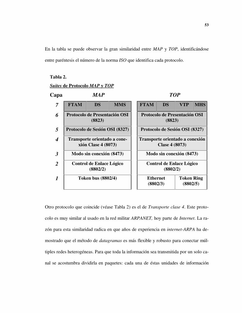
En la tabla se puede observar la gran similaridad entre MAP y TOP, identificándose
entre paréntesis el número de la norma ISO que identifica cada protocolo.
Otro protocolo que coincide (véase Tabla 2) es el de Transporte clase 4. Este proto-
colo es muy similar al usado en la red militar ARPANET, hoy parte de Internet. La ra-
zón para esta similaridad radica en que años de experiencia en internet-ARPA ha de-
mostrado que el método de datagramas es más flexible y robusto para conectar múl-
tiples redes heterogéneas. Para que toda la información sea transmitida por un solo ca-
nal se acostumbra dividirla en paquetes: cada una de éstas unidades de información
Tabla 2.
Suites de Protocolo MAP y TOP
Capa MAP TOP
7 FTAM DS MMS FTAM DS VTP MHS
6 Protocolo de Presentación OSI(8823)
Protocolo de Presentación OSI(8823)
5 Protocolo de Sesión OSI (8327) Protocolo de Sesión OSI (8327)
4 Transporte orientado a cone-xión Clase 4 (8073)
Transporte orientado a conexiónClase 4 (8073)
3 Modo sin conexión (8473) Modo sin conexión (8473)
2 Control de Enlace Lógico(8802/2)
Control de Enlace Lógico(8802/2)
1 Token bus (8802/4) Ethernet(8802/3)
Token Ring(8802/5)
54
debe poseer información asociada a cada capa, de allí el término datagrama. Las in-
formaciones de identidad y destino son relevantes en cada paquete para poder proveer
el enrutamiento, así como también es necesario un mecanismo de detección de errores:
todo sistema de información tiene una probabilidad de error, por lo que se debe mane-
jar un protocolo que retransmita la información en caso de ser necesario. En el caso de
ARPA se supuso que la red no era confiable, especialmente durante una guerra, y se
deseaba que los paquetes de información pudieran seguir rutas alternas. El haber pen-
sado la red de esta manera, es decir con una capa de transporte robusta pero compleja,
ha hecho posible que MAP y TOP puedan enlazarse a casi cualquier tipo de red.
2.8 EL NIVEL DE APLICACIÓN EN MAP
MAP y TOP implementan un subconjunto de las aplicaciones del modelo OSI. Como
el objetivo de OSI es comunicar computadores distintos, solo se especificaron proto-
colos de comunicación entre máquinas; nunca se impuso limitaciones a los diseñadores
de aplicaciones. Bajo estas condiciones, lo único importante es que el software cumpla
su función y esto usualmente ocurre de alguna manera que depende de la máquina
particular.

55
Para los diseñadores de MAP, era inaceptable tener que cambiar los programas tan
pronto se adquiriera una nueva tarjeta MAP; es decir no debería haber dependencia
entre máquinas. Por este motivo, los diseñadores de MAP decidieron dar condiciones
adicionales a las de OSI y para ello dedicaron 2300 páginas en la especificación MAP.
El resto de este capitulo es dedicado casi con exclusividad a MAP ya que es la red más
relacionada con la manufactura en planta.
2.8.1 Aplicaciones MAP
La especificación MAP define cinco contextos de aplicaciones: Private, Manufactu-
ring Message Specification (MMS), File Transfer Access Management (FTAM),
Administración de la Red, y Servicios de Directorio. De estos cinco, el programador
de aplicaciones usa, típicamente, los primeros tres:
• Private: es el más simple de los contextos; provee acceso directo al Application
Common Service Element (ACSE), y al nivel de Presentación (capa 6). Un progra-
ma de aplicación establece una asociación de contexto privado con otro programa
para intercambiar información sin estructura.
• Manufacturing Message Specification (MMS): soporta el intercambio de mensajes
entre el programa de aplicación y los dispositivos de la planta tales como controla-
dores numéricos, robots, y controladores lógicos programables. El intercambio de
56
información se da en formatos de mensajes definidos de acuerdo a la capacidad del
dispositivo particular.
• File Transfer Access Management (FTAM): este contexto soporta operaciones del
programa de aplicación sobre archivos que pueden estar en cualquier parte de la
red. Ejemplos de funciones de alto nivel son: copia de archivos, mover, borrar, leer
atributos, y cambiar atributos. Ejemplos de funciones FTAM de bajo nivel son:
abrir, cerrar, crear, borrar, leer, y escribir.
La versión 3.0 de MAP define un Application Service Element (ASE) para cada uno
de estos contextos, que provee el servicio requerido en cada caso. Para que cada pro-
grama de aplicación use los servicios específicos de contexto, provistos por el ASE, se
ha definido una Application Programming Interface (API). Los API´s están definidos
en términos de llamadas de funciones al contexto ASE y los bloques de control de in-
formación para pasar parámetros específicos de función entre el programa de aplica-
ción y el ASE de contexto.

57
2.8.2 Manufacturing Message Specification (MMS)
La aplicación que marca claramente la diferencia entre MAP y las demás redes ISO,
incluyendo TOP, es la Especificación de Mensajes de Manufactura, MMS. Este proto-
colo está especificado en la norma ISO 9506 y sus normas compañeras. MMS es un
sistema de mensajes, aceptado internacionalmente, para el intercambio de datos en
tiempo real e información de supervisión de control entre dos dispositivos en red o
Físico
Enlace
Red
Medio Físico
Transporte
Sesión
Presentación
Nivel de Aplicación
ACSE
ASE ASE ASE
Privado FTAM MMS(API) (API) (API)
Figura 6. El Nivel de Aplicaciones en MAP.
58
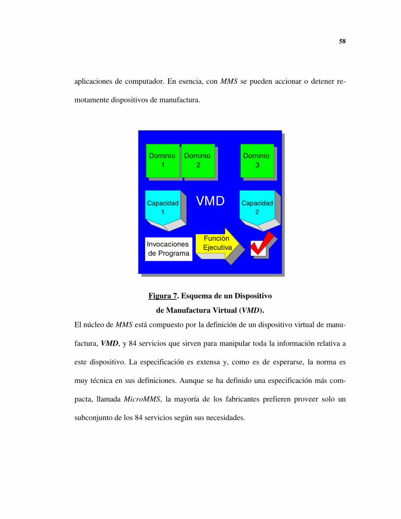
aplicaciones de computador. En esencia, con MMS se pueden accionar o detener re-
motamente dispositivos de manufactura.
VMD
Dominio 1
Capacidad1
Dominio 2
Dominio 3
Capacidad2
Función EjecutivaInvocaciones
de Programa
Figura 7. Esquema de un Dispositivo
de Manufactura Virtual (VMD).
El núcleo de MMS está compuesto por la definición de un dispositivo virtual de manu-
factura, VMD, y 84 servicios que sirven para manipular toda la información relativa a
este dispositivo. La especificación es extensa y, como es de esperarse, la norma es
muy técnica en sus definiciones. Aunque se ha definido una especificación más com-
pacta, llamada MicroMMS, la mayoría de los fabricantes prefieren proveer solo un
subconjunto de los 84 servicios según sus necesidades.

59
El dispositivo virtual consta de cuatro elementos básicos: una función ejecutiva, capa-
cidades, invocaciones de programas y dominios:
• Una capacidad es una descripción que provee el fabricante, en forma cadena de
caracteres, para identificar los recursos de su maquina: un controlador, por ejem-
plo, puede estar conectado a varias máquinas herramientas y por tanto tener varias
capacidades.
• Los dominios son recursos necesarios para ejecutar la función especifica: memoria,
disco, etc.
• Las invocaciones de programa son conjuntos de elementos, instrucciones o infor-
mación que coordinan las actividades a realizar para completar la función.
Al sofisticado VMD se le suma otro objeto; el Event Object Manager (EOM), cuya
función es la de coordinar toda la comunicación entre los diversos interesados, usua-
rios locales y en red, y el VMD. Por supuesto, estos objetos son imaginarios; abstrac-
ciones que representan dispositivos verdaderos o sus comportamientos.
Aunque MMS es independiente de la función realizada y del desarrollador del disposi-
tivo o aplicación, existen normas compañeras con la ISO 9056 que determinan carac-
terísticas específicas para robots, PLC’s y controladores numéricos. Ralph Ma-
ckiewicz, vicepresidente de Cisco, ha trabajado varios años con MMS y ha donado
60
gentilmente el documento que se incluye en el Anexo B, donde se describe con mayor
profundidad el protocolo MMS. Este documento es un aporte importante por la difi-
cultad de encontrar documentación cualitativa sobre este protocolo.
Pese a la gran utilidad de usar un modelo cliente-servidor en un proceso de manufactu-
ra, y a la normatividad existente, la utilización de MMS se ha visto limitada por dos
factures:
1. Los productos MMS son, en general, costosos. Muchos productos son desarrolla-
dos para computadores o redes de fabricantes específicos.
2. Muchos dispositivos de manufactura no poseen soporte para MMS debido a la
complejidad del protocolo: en general, solo los dispositivos más costosos y sofisti-
cados poseen MMS.
Aunque no se posea una red MAP, MMS puede ser implementada sobre otras redes,
por lo cual conviene tenerlo en cuenta en futuros desarrollos de dispositivos. Una po-
sibilidad flexible y eficaz es usar el protocolo TCP-IP, el más usado en las redes co-
merciales, para implementar servicios OSI: una implementación de este tipo se ha pro-
puesto como estándar para permitir una transición de Internet a una futura red OSI.
En el Anexo A se presentan los lineamientos RFC 10068, en los que se basan este tipo
8 N.A: RFC significa Request For Comments; es un documento de libre distribución destinado a definir normas
de Internet.

61
de desarrollos. Raymond Seng-Sim Cheah, Bo-Sung Lee y Long Lim9, de la Universi-
dad Tecnológica de Nanyang, Singapur, parten de ISODE para implementar MMS
sobre una internet. Una implementación de este tipo presenta todas las ventajas que
tiene una red de manufactura y evita la inversión costosa en tarjetas Token Bus.
9 CHEAH, LEE y LIM, Implementing Manufacturing Message Specification Services and Protocol Using ISO
Development Environment, IEEE TENCON’93 Beijing

MODELO DEL CONTROLADOR NUMÉRICO
En el proceso de diseño del software deseado hay dos pasos necesarios: el modela-
miento del sistema a controlar y la determinación de las necesidades del software. Am-
bos temas se relacionan demasiado por lo que se decidió estudiarlos de manera parale-
la.
El modelo de control planteado por Michel Moreaux10 de la École Polytechnique Fe-
derale de Lausanne11 presenta varias características a tener en cuenta:
1. Se identifica el control como un problema con requerimientos en tiempo real, lo
cual obliga a considerar el sincronismo por encima de la respuesta en tiempo.
2. Se identifica una jerarquía en las operaciones que se deben cumplir.
10 Michael Moreaux, A CNC model well-suited for the requirements of CNC software construction environment.
Proceedings of CompEuro 93, Paris, Francia, 1993.
11 http://litsun.epfl.ch
63
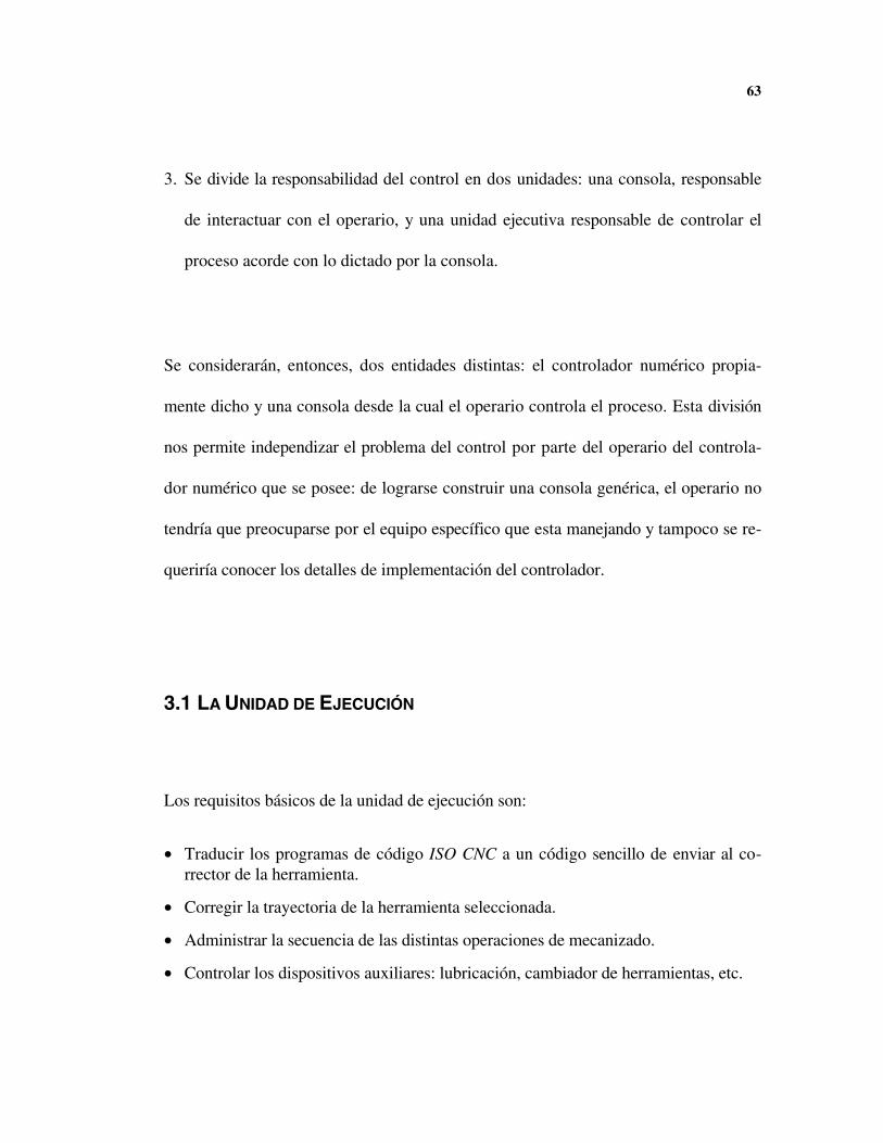
3. Se divide la responsabilidad del control en dos unidades: una consola, responsable
de interactuar con el operario, y una unidad ejecutiva responsable de controlar el
proceso acorde con lo dictado por la consola.
Se considerarán, entonces, dos entidades distintas: el controlador numérico propia-
mente dicho y una consola desde la cual el operario controla el proceso. Esta división
nos permite independizar el problema del control por parte del operario del controla-
dor numérico que se posee: de lograrse construir una consola genérica, el operario no
tendría que preocuparse por el equipo específico que esta manejando y tampoco se re-
queriría conocer los detalles de implementación del controlador.
3.1 LA UNIDAD DE EJECUCIÓN
Los requisitos básicos de la unidad de ejecución son:
• Traducir los programas de código ISO CNC a un código sencillo de enviar al co-rrector de la herramienta.
• Corregir la trayectoria de la herramienta seleccionada.
• Administrar la secuencia de las distintas operaciones de mecanizado.
• Controlar los dispositivos auxiliares: lubricación, cambiador de herramientas, etc.

64
• Generar la trayectoria.
• Controlar los ejes.
• Comunicarse con la red, si ésta existe.
Como se ve, la unidad de ejecución es la de mayor responsabilidad durante el proceso:
esta responsabilidad es aún mayor cuando se opera remotamente o de manera autó-
noma ya que la consola, y a veces el operario, desaparece.
En el modelo de Moreaux, el controlador numérico está compuesto por una jerarquía
de Máquinas de Estado Finito: es decir, células especializadas con funciones específi-
cas cuyo estado se puede determinar con un número finito de variables. Los niveles
más altos de esta jerarquía están constituidos por los sistemas de comunicación, y los
niveles más bajos por las unidades de operación.

65
Aquí se pretende distribuir inteligentemente los controles de tal forma que cada unidad
tenga lo exclusivamente necesario para cumplir su función. Al mantener los controles
muy sencillos se obtiene una disminución en los costos de los equipos y se le da mayor
flexibilidad al sistema.
3.2 LA UNIDAD CONSOLA
Los requisitos básicos de la consola genérica son:
Comandos
Máquina de Estado
Finito
Unidad FuncionalCorr.Herr.
Máquina de Estado
Finito
Unidad FuncionalCamb.Her
Máquina de Estado
Finito
Unidad Funcional
Eje X
Unidad FuncionalTrad. ISO
Unidad Consola
Nivel Superior
(Raíz)
Niveles Inferiores (hojas)
UnidadesFuncionales
Figura 8. Modelo Moreaux de un Controlador Numérico.
66
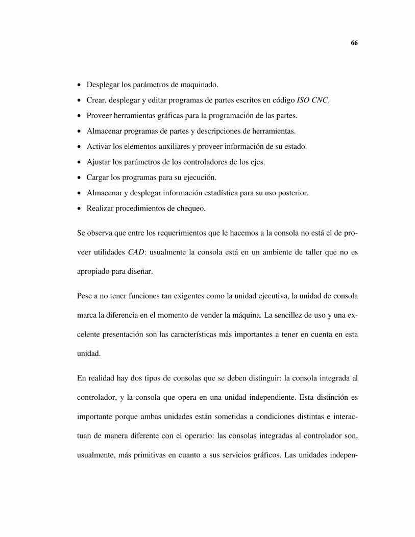
• Desplegar los parámetros de maquinado.
• Crear, desplegar y editar programas de partes escritos en código ISO CNC.
• Proveer herramientas gráficas para la programación de las partes.
• Almacenar programas de partes y descripciones de herramientas.
• Activar los elementos auxiliares y proveer información de su estado.
• Ajustar los parámetros de los controladores de los ejes.
• Cargar los programas para su ejecución.
• Almacenar y desplegar información estadística para su uso posterior.
• Realizar procedimientos de chequeo.
Se observa que entre los requerimientos que le hacemos a la consola no está el de pro-
veer utilidades CAD: usualmente la consola está en un ambiente de taller que no es
apropiado para diseñar.
Pese a no tener funciones tan exigentes como la unidad ejecutiva, la unidad de consola
marca la diferencia en el momento de vender la máquina. La sencillez de uso y una ex-
celente presentación son las características más importantes a tener en cuenta en esta
unidad.
En realidad hay dos tipos de consolas que se deben distinguir: la consola integrada al
controlador, y la consola que opera en una unidad independiente. Esta distinción es
importante porque ambas unidades están sometidas a condiciones distintas e interac-
tuan de manera diferente con el operario: las consolas integradas al controlador son,
usualmente, más primitivas en cuanto a sus servicios gráficos. Las unidades indepen-
67
dientes son, comúnmente, PC´s o terminales adaptadas para que funcionen con el
controlador numérico. Las unidades modernas basadas en PCs vienen dotadas con un
mouse: tal dispositivo no es el más adecuado para un ambiente de taller por lo que
siempre se deben ofrecer alternativas como teclados o pantallas touchscreen.
La división entre unidad ejecutiva y consola surge naturalmente ya que ambas unida-
des frecuentemente están divididas físicamente. La consola también tiene divisiones,
pero éstas son mucho mas sutiles: a nivel funcional sabemos que el acto de editar una
programa es muy distinto al de ejecutarlo. Tenemos, por tanto, dos unidades funciona-
les distintas, un editor y un controlador en software, que deben interactuar de manera
cercana.
PROGRAMACIÓN DE UNA MÁQUINA HERRAMIENTA CNC
4.1 CONTROLES
Los controles son el corazón de la máquina herramienta: entre más fácil sea controlar
la máquina mas fácil será ponerla a producir.
Un área que puede causar confusión, al seleccionar una MHCN, es la velocidad de la
máquina. Es posible alcanzar movimientos rápidos de hasta 0.5 m/s, sin embargo, no
todas las partes lo requieren: el ciclo de producción se beneficiará si el proceso apro-
vecha los movimientos de alta velocidad la mitad o más del tiempo.
Las relaciones de contorneado pueden ser de hasta de hasta 1,000 bloques por segun-
do. Es posible, sin embargo, que algunas máquinas anuncien altas velocidades de
contorneado y no las puedan alcanzar: en una máquina que este conectada con DNC a
una razón de 38,400 baudios, realizando movimientos sencillos X y Y, la velocidad de
comunicación limita la máquina a 250 bloques/segundo. Si el sistema usa WindowsTM,

69
o algún otro ambiente gráfico, la velocidad será aún menor, debido a la existencia de
otras tareas que ocupan al computador. Es de notar que el aumento de velocidad y las
mejoras en los sistemas operativos actuales tienden a reducir este efecto, pero las re-
comendaciones de los fabricantes siguen orientadas a dedicar un computador por con-
trolador CNC. Los bajos precios de los computadores justifican esta decisión.
La mayoría de las máquinas CNC comerciales usan controladores compatibles con Fa-
nucTM: las máquinas más costosas usan los controladores Fanuc originales pero, debi-
do a los altos costos de esta marca, los fabricantes han optado por producir sus pro-
pios controladores y hacerlos compatibles.
Aunque la mayoría de los controladores usan códigos G para ejecutar los movimientos
de la máquina, hay programas de mayor nivel que facilitan la carga de programación:
los programas CAM son capaces de generar movimientos y superficies complejas,
mientras otros programas usan ambientes gráficos con iconos y preguntas. Si el siste-
ma es propio del centro de mecanizado el operario deberá aprender varios sistemas
distintos, dependiendo de las máquinas que estén en uso. Existen códigos gráficos
normalizados para los centros de control numérico convencionales pero son de poca
utilidad en los ambientes de programación.
70
4.2 INSTRUCCIONES OPERACIONALES
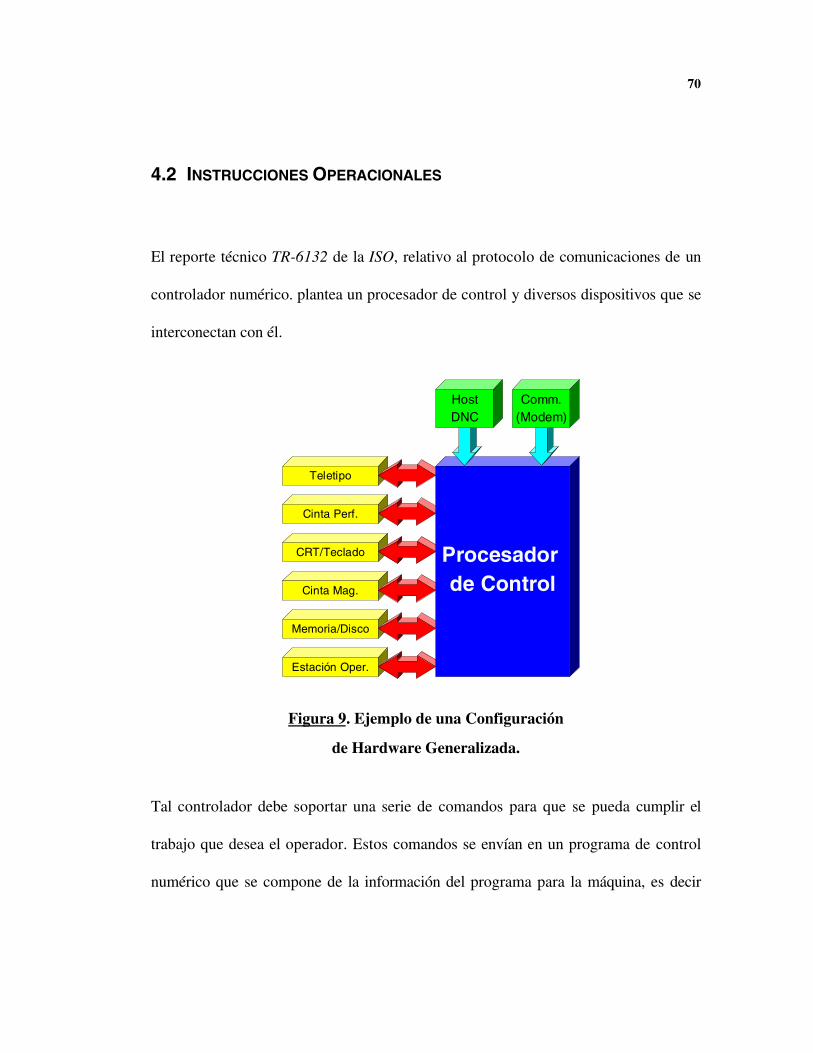
El reporte técnico TR-6132 de la ISO, relativo al protocolo de comunicaciones de un
controlador numérico. plantea un procesador de control y diversos dispositivos que se
interconectan con él.
Teletipo
Estación Oper.
Memoria/Disco
Cinta Mag.
CRT/Teclado
Cinta Perf.
Procesador de Control
HostDNC
Comm.(Modem)
Figura 9. Ejemplo de una Configuración
de Hardware Generalizada.
Tal controlador debe soportar una serie de comandos para que se pueda cumplir el
trabajo que desea el operador. Estos comandos se envían en un programa de control
numérico que se compone de la información del programa para la máquina, es decir

71
los códigos G, y de instrucciones operativas. Las instrucciones operativas se separan
de la información del programa por los paréntesis que las encierran. Estos paréntesis,
de hecho, actúan como señales de encendido y apagado de una modalidad específica
de control.
Las instrucciones operativas son comandos de bajo nivel, en forma mnemónica, que
definen operaciones internas para controlar el procesamiento de la información o con-
figurar el controlador. Las instrucciones operativas no bastan, por sí solas, para gene-
rar acciones en la máquina de control numérico.
Las instrucciones operacionales están organizadas en una sencilla jerarquía de acuerdo
a su funcionalidad.
Comandos de Edición
Comandos para Manejo de Archivos
Comandos Universales
Selector de Modalidad
Comandos de Control de
Máquina
Figura 10. Jerarquía de las Instrucciones Operativas
72
Como se observa en la figura, no habrá acceso a ningún comando operativo hasta
tanto no se seleccione esa modalidad específica. Para seleccionar alguna modalidad
ésta debe activarse directamente en el controlador y usarse con el teclado, o deben
enviarse los comandos entre paréntesis junto con el resto del programa.
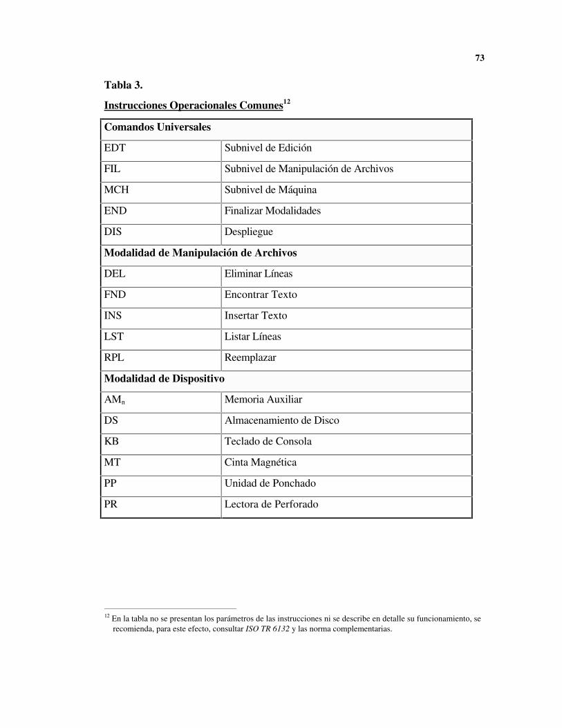
Los comandos, llamados mnemónicos por su similaridad al lenguaje de máquina de un
computador, permiten la manipulación de los datos almacenados y de los dispositivos
secundarios. A continuación se presentan los significados de algunos mnemónicos co-
munes, aclarándose que el fabricante esta en libertad de añadir o retirar algunas in-
trucciones por lo cual se debe consultar los comandos y sus parámetros en el manual
del equipo.
73
12 En la tabla no se presentan los parámetros de las instrucciones ni se describe en detalle su funcionamiento, se
recomienda, para este efecto, consultar ISO TR 6132 y las norma complementarias.
Tabla 3.
Instrucciones Operacionales Comunes12
Comandos Universales
EDT Subnivel de Edición
FIL Subnivel de Manipulación de Archivos
MCH Subnivel de Máquina
END Finalizar Modalidades
DIS Despliegue
Modalidad de Manipulación de Archivos
DEL Eliminar Líneas
FND Encontrar Texto
INS Insertar Texto
LST Listar Líneas
RPL Reemplazar
Modalidad de Dispositivo
AMn Memoria Auxiliar
DS Almacenamiento de Disco
KB Teclado de Consola
MT Cinta Magnética
PP Unidad de Ponchado
PR Lectora de Perforado
74
4.3 INFORMACIÓN DE PROGRAMACIÓN
4.3.1 Información Geométrica
La mayoría de los fabricantes ofrecen programación en códigos G, un lenguaje que
usa códigos predefinidos para controlar los movimientos de la máquina. Los códigos
G estan normalizados por la ISO-EIA en la norma ISO 6983 “Numerical control of
Machines”. Se debe notar que la mayoría de fabricantes americanos tratan de cumplir
esta norma pero hacen variaciones y modificaciones de acuerdo a las características
propias de su producto.
Los códigos G son usados para especificar movimiento, caso en que se denominan
códigos G de eventos, o para realizar funciones en el controlador CNC, caso en el que
se llaman códigos G preparatorios. Existen códigos G para eventos especiales que de-
notan operaciones más complejas como roscados.
Algunos controladores recientes toman medidas de anticipación al cambiar las condi-
ciones de operación. Un ejemplo típico es disminuir la velocidad de mecanizado cuan-
do se va a dar un cambio brusco de sección, de esta manera se provee un mejor termi-
nado en la pieza.
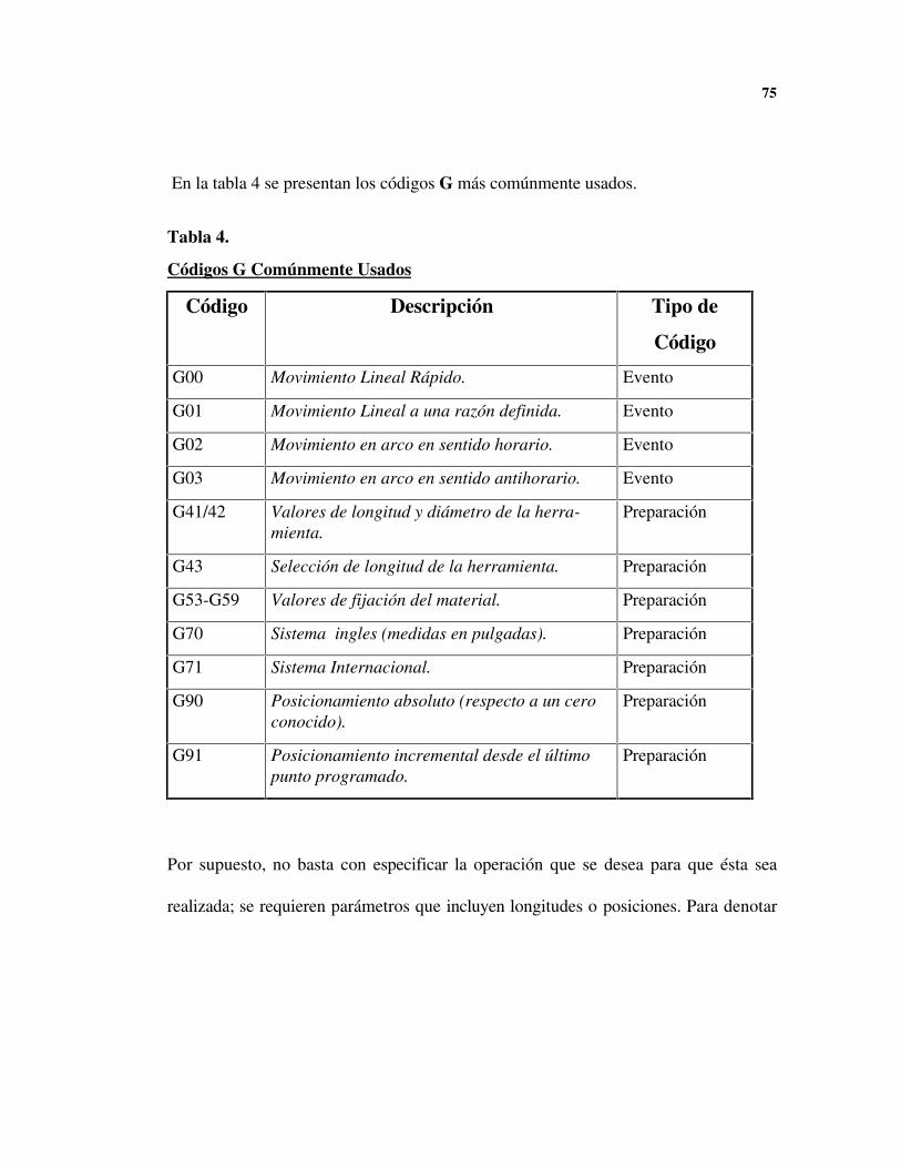
75
En la tabla 4 se presentan los códigos G más comúnmente usados.
Tabla 4.
Códigos G Comúnmente Usados
Código Descripción Tipo de
Código
G00 Movimiento Lineal Rápido. Evento
G01 Movimiento Lineal a una razón definida. Evento
G02 Movimiento en arco en sentido horario. Evento
G03 Movimiento en arco en sentido antihorario. Evento
G41/42 Valores de longitud y diámetro de la herra-mienta.
Preparación
G43 Selección de longitud de la herramienta. Preparación
G53-G59 Valores de fijación del material. Preparación
G70 Sistema ingles (medidas en pulgadas). Preparación
G71 Sistema Internacional. Preparación
G90 Posicionamiento absoluto (respecto a un ceroconocido).
Preparación
G91 Posicionamiento incremental desde el últimopunto programado.
Preparación
Por supuesto, no basta con especificar la operación que se desea para que ésta sea
realizada; se requieren parámetros que incluyen longitudes o posiciones. Para denotar
76
estos parámetros los comandos G, y algunos otros comandos que se describirán mas
adelante, usan palabras y registros.
Las palabras constan de un índice que el controlador identifica (X, Y, Z, Y, J, etc.) se-
guido de un valor. Por ejemplo, la palabra Y2.45 le indicaría al controlador que debe
desplazarse a la posición 2.45 sobre el eje Y. Además del rango que poseen todas las
palabras, se debe considerar el formato y si se usa, o no, el punto decimal, lo cual de-
pende del sistema de unidades seleccionado anteriormente.
Los registros son valores almacenados en el controlador con anterioridad. Usualmente
se designan usando una letra distinta a la de las palabras válidas (H, D, etc.) y un nú-
mero entre 0 y 99. Los registros son usados solo por algunos códigos G y son muy
útiles para almacenar propiedades de las herramientas.
4.3.2 Información Tecnológica
Además de los comandos que realizan las operaciones de mecanizado el integrador del
control, la persona que incluye el controlador en la máquina CNC, define códigos M
que se utilizan para realizar funciones diversas. La norma EIA original no especifica
códigos M, pero la norma ISO se mencionan algunos. En la tabla 5 se presentan algu-
nos códigos M comunes.

77
El comando M06, cambio de herramienta, algunas veces viene precedido por un co-
mando T que identifica la herramienta que se debe preparar. Las máquinas que cuentan
con cambiador automático de herramientas, ATC13, seguirán operando sin interrup-
ción, pero las que no lo tienen se retraen y detienen su funcionamiento para que el
operario cambie la herramienta y dé la señal de proseguir.
4.4 ESTRUCTURA GENERAL
13 ATC significa Automatic Tool Changer
Tabla 5.
Algunos Códigos M
Código Descripción
M02 / M30 Fin del Programa CNC.
M03 Encender husillo, sentido horario.
M04 Encender husillo, sentido antihorario.
M05 Apagar husillo.
M06 Cambio de herramientas.
M08 Abrir llave de refrigerante.
M09 Cerrar llave de refrigerante.

78
Los programas NC deben ser estructurados de tal forma que el programa funcione de
manera segura, confiable y consistente cada vez que se ejecute. Algunos controladores
requieren un comando % al comenzar el programa. El programa usualmente debe ini-
ciar con lo que se denomina un bloque de seguridad: este bloque debe incluir códigos
G que configuran la maquina en los modos de operación deseados. El bloque de segu-
ridad debe definir las unidades, o si se están usando coordenadas incrementales o abso-
lutas, también se deben tener en cuenta valores iniciales como la longitud de la herra-
mienta.
Muchos de los pasos del bloque de seguridad se repiten durante los cambios de he-
rramienta: apagar o prender el refrigerante y posicionar las piezas. Cuando se desea
seguir usando la misma herramienta para una operación distinta se usa un cambio nulo
de herramienta, es decir se omiten el comando M06 y los comandos que especifican la
herramienta. Esta acción tiene la virtud de permitir la continuación del programa NC
desde el punto de cambio de herramienta en caso de que alguna herramienta se rompa
y se deba comenzar a maquinar el vacío.
La mayoría de los controles almacenan el estado definido en el programa anterior y no
es necesario volver a programar todos los datos, esta facilidad, muy apreciada en la
época de las cintas perforadas, se denomina modalidad.
79
El siguiente paso es definir los movimientos deseados para fabricar la pieza. Las má-
quinas CNC solo pueden hacer dos tipos de movimientos: lineales y circulares. Las
formas más complicadas deberán componerse, necesariamente de secciones circulares
o rectas. Los movimientos lineales se realizan a dos velocidades distintas: una veloci-
dad alta, denominada movimiento rápido que se utiliza comúnmente para posicionar la
herramienta, y un movimiento a la velocidad predefinida durante el cual habrá desbaste
de material. El movimiento circular se refiere a cualquier movimiento que comprenda
desplazamiento sobre un arco a un radio dado. El movimiento circular también se divi-
de en dos: uno en el sentido de las manecillas del reloj y otro contrario al sentido de
las manecillas.
Después de terminar las operaciones, el final del programa debe apagar el refrigerante
y el husillo, y la herramienta debe regresar a su hogar. Usualmente se debe dar un co-
mando adicional, M02, para indicar el fin del programa.
Lógicamente, hay importantes diferencias entre los comandos que requiere una fresa-
dora, un torno, o un controlador numérico genérico: estas diferencias se reflejan en la
implementación misma del conjunto de instrucciones que puede recibir la máquina
CNC. El Anexo A resume los comandos básicos de las maquinas M3T del Centro Co-
lombo-Italiano en el Servicio Nacional de Aprendizaje, SENA.
80
4.5 POSTPROCESADORES Y CLDATA
Un problema que se enfrenta en la planta de hoy es la falta de normalización de los
formatos de control numérico. Si bien los códigos G se usan indistintamente en tornos
y fresadoras, estos no son iguales en todas las maquinas herramientas; más aún, el
software de distintas máquinas no es intercambiable por diferencias en las interfaces y
la representación interna de la información.
Las dificultades por interfaces entre los sistemas CAD/CAM y el equipo NC de la
planta frecuentemente comienzan en la etapa del postprocesador: el postprocesador es
software especial que se encarga de cambiar el formato de la salida de un programa, o
de un sistema computarizado NC, al formato exacto que requiere el sistema o el dis-
positivo máquina-herramienta.
El sistema que se usa para asistir el proceso numérico, usualmente un paquete CAM,
produce siempre un archivo CLDATA, es decir, un archivo de información cutter lo-
cation (CL) con los datos requeridos para definir la trayectoria y el movimiento de la
herramienta de corte.
La información CLDATA no incluye las características individuales y dinámicas de la
máquina herramienta que se va a utilizar, por lo que el archivo CL debe ser procesado
81
y convertido al formato específico del sistema particular; es decir, debe ser postproce-
sado. Lógicamente, sistemas distintos requerirán postprocesadores distintos, lo cual
quiere decir que entre mayor variedad de combinaciones máquina-herramienta haya en
la planta, mas postprocesadores se requerirán. Obtener post-procesadores puede ser
problemático: usualmente son costosos por la dificultad de su implementación y re-
quieren personal técnico para mantenerlos o brindarles soporte.
En un intento por solucionar algunos de estos problemas, se desarrolló el formato
normalizado de control numérico EIA RS-949 denominado Binary Cutter Location,
BCL. La idea original fue normalizar el formato CLDATA generado por procesadores
Automated Programmed Tool, APT, y usarlo como entrada común para máquinas he-
rramientas. Diversas instituciones de normalización, incluyendo DIN, ofrecen norma-
tividad de CLDATA, pero BCL tiene la virtud de no estar restringido a sistemas APT;
se puede usar además con programas CAD/CAM y lenguajes de programación NC que
generan archivos intermedios CL.
El precursor de este movimiento fue la compañía Rockwell International, que en 1974
poseía siete sistemas distintos, con 13 formatos de cinta y 23 postprocesadores. En
1975 se comenzó la unificación del formato de entrada a los postprocesadores, consis-
tente en un formato con palabras de 32 bits, y en 1980 se propuso este formato como
82
una norma oficial de la industria, aunque el documento final solo fue publicado en
1983 por la Electronic Industries Asociation, EIA.
El protocolo, en esencia, resulta de utilizar APT para generar código binario de 32
bits: como el código binario se compone de unos y ceros es independiente del código
alfanumérico de la máquina en que se procesa. La norma ISO no esta disponible aún
en Colombia y adquirirla implica pagar portes de nacionalización, además de los im-
puestos normales.
Las ventajas de BCL son:
• Elimina el costo y la dificultad de adquirir, corregir, y mantener un gran número de
postprocesadores.
• Soluciona los problemas de incompatibilidad del programa NC dando como resul-
tado portabilidad de programas entre máquinas herramientas.
Los sistemas de programación NC producen salidas en diversos formatos pero actual-
mente hay pocos vendedores de software CAD/CAM que soportan RS-494 como op-
ción de salida. Una solución para este problema es el desarrollo o adquisición por
parte del usuario de una utilidad de conversión CL.
La figura 11, a continuación. ilustra el proceso que se sigue tradicionalmente y el re-
sultante al usar BCL.

83
Un conversor CL da formato a los datos de rutas de mecanizado en el software exis-
tente para que sea compatible con el especificado por la norma RS-494. Como las co-
ordenadas se calculan en tiempo real en la máquina BCL, el conversor usará menos re-
cursos de procesamiento que el postprocesador convencional y producirá programas
más cortos.
post procesador
Programa para NC
CNC 1
Programa Fuente
Procesador NC
Información CL
post procesador
Programa para NC
CNC 2
post procesador
Programa para NC
CNC 3
(a) Postprocesadores Convencionales.
RS- 494 CNC 1
Programa Fuente
Procesador NC
Información CL
Utilidad de Conversión
BCL
Programa BCL para Máquinas
RS-494
RS-494 CNC 2
RS-494 CNC 3
(b) RS-494 BCL.
Figura 11. CLDATA Convencional vs. BCL.

84
Para los usuarios que no poseen máquinas compatibles con BCL no se justifica actuali-
zar la máquina sólo para usar BCL, por lo que también se consiguen unidades de pos-
tproceso de BCL para la máquina individual.
Gracias a la gran demanda de la industria aerospacial, el sistema BCL esta ampliamen-
te difundido en los Estados Unidos. Algunas empresas que lo soportan son: Cincinatti
Milacron, Allen Bradley, Automation Intelligence, y Justice Peterson & Associates,
además de algunas empresas de CAD/CAM. En Europa, en cambio, el sistema está
muy poco difundido y pocas empresas lo conocen.
DESARROLLOS ANTERIORES EN LA UNIVERSIDAD NACIONAL
5.1 PROTOTIPO DE UNA MESA POSICIONADORA
Durante los últimos años el Servicio Nacional de Aprendizaje, SENA, y el Departa-
mento de Ingeniería Mecánica de la Universidad Nacional (U. N.) han trabajado con-
juntamente en diversos proyectos de manufactura automatizada.
La experiencia entre las dos instituciones ha sido fructífera; en particular se ha cons-
truido una mesa posicionadora con sus controles electrónicos.
Aunque el proyecto ha sido un éxito en cuanto a la eficacia de la máquina, la mesa
posicionadora está lejos de poderse comercializar debido a los altos costos que com-
prenden los controladores usados, y a que se debe trabajar más en su eficiencia y con-
fiabilidad.
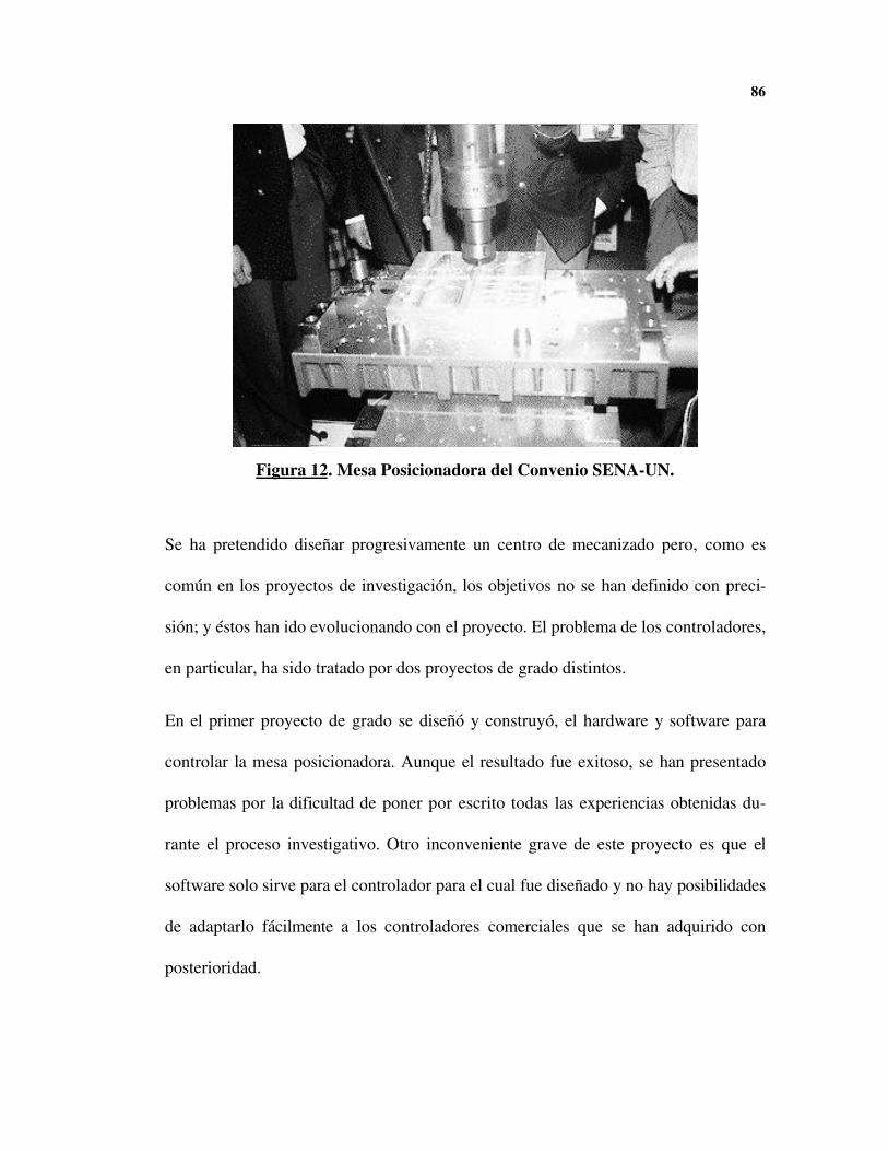
86
Se ha pretendido diseñar progresivamente un centro de mecanizado pero, como es
común en los proyectos de investigación, los objetivos no se han definido con preci-
sión; y éstos han ido evolucionando con el proyecto. El problema de los controladores,
en particular, ha sido tratado por dos proyectos de grado distintos.
En el primer proyecto de grado se diseñó y construyó, el hardware y software para
controlar la mesa posicionadora. Aunque el resultado fue exitoso, se han presentado
problemas por la dificultad de poner por escrito todas las experiencias obtenidas du-
rante el proceso investigativo. Otro inconveniente grave de este proyecto es que el
software solo sirve para el controlador para el cual fue diseñado y no hay posibilidades
de adaptarlo fácilmente a los controladores comerciales que se han adquirido con
posterioridad.
Figura 12. Mesa Posicionadora del Convenio SENA-UN.
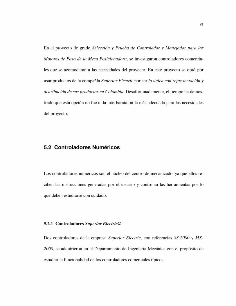
87
En el proyecto de grado Selección y Prueba de Controlador y Manejador para los
Motores de Paso de la Mesa Posicionadora, se investigaron controladores comercia-
les que se acomodaran a las necesidades del proyecto. En este proyecto se optó por
usar productos de la compañía Superior Electric por ser la única con representación y
distribución de sus productos en Colombia. Desafortunadamente, el tiempo ha demos-
trado que esta opción no fue ni la más barata, ni la más adecuada para las necesidades
del proyecto.
5.2 Controladores Numéricos
Los controladores numéricos son el núcleo del centro de mecanizado, ya que ellos re-
ciben las instrucciones generadas por el usuario y controlan las herramientas por lo
que deben estudiarse con cuidado.
5.2.1 Controladores Superior Electric©©
Dos controladores de la empresa Superior Electric, con referencias SS-2000 y MX-
2000, se adquirieron en el Departamento de Ingeniería Mecánica con el propósito de
estudiar la funcionalidad de los controladores comerciales típicos.
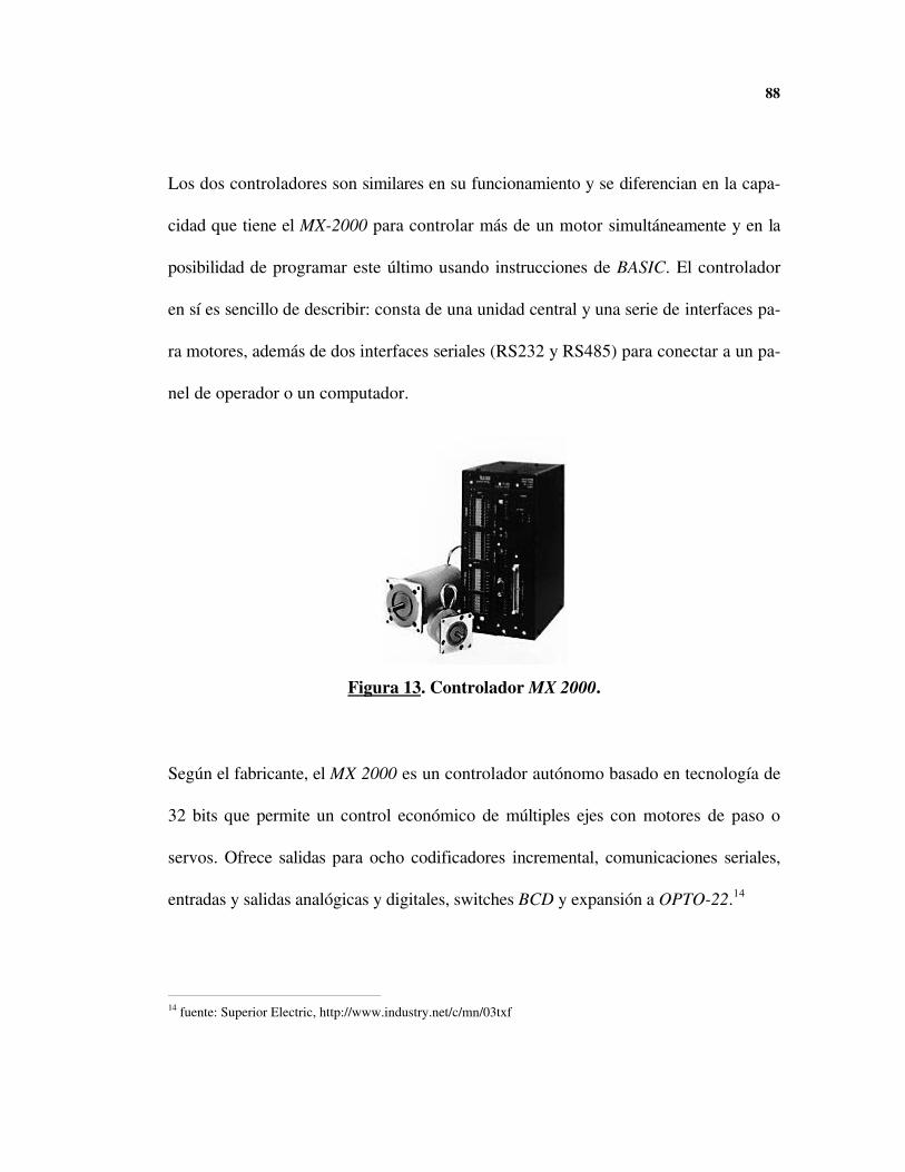
88
Los dos controladores son similares en su funcionamiento y se diferencian en la capa-
cidad que tiene el MX-2000 para controlar más de un motor simultáneamente y en la
posibilidad de programar este último usando instrucciones de BASIC. El controlador
en sí es sencillo de describir: consta de una unidad central y una serie de interfaces pa-
ra motores, además de dos interfaces seriales (RS232 y RS485) para conectar a un pa-
nel de operador o un computador.
Figura 13. Controlador MX 2000.
Según el fabricante, el MX 2000 es un controlador autónomo basado en tecnología de
32 bits que permite un control económico de múltiples ejes con motores de paso o
servos. Ofrece salidas para ocho codificadores incremental, comunicaciones seriales,
entradas y salidas analógicas y digitales, switches BCD y expansión a OPTO-22.14
14 fuente: Superior Electric, http://www.industry.net/c/mn/03txf
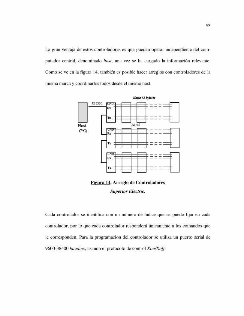
89
La gran ventaja de estos controladores es que pueden operar independiente del com-
putador central, denominado host, una vez se ha cargado la información relevante.
Como se ve en la figura 14, también es posible hacer arreglos con controladores de la
misma marca y coordinarlos todos desde el mismo host.
Figura 14. Arreglo de Controladores
Superior Electric.
Cada controlador se identifica con un número de índice que se puede fijar en cada
controlador, por lo que cada controlador responderá únicamente a los comandos que
le corresponden. Para la programación del controlador se utiliza un puerto serial de
9600-38400 baudios, usando el protocolo de control Xon/Xoff.
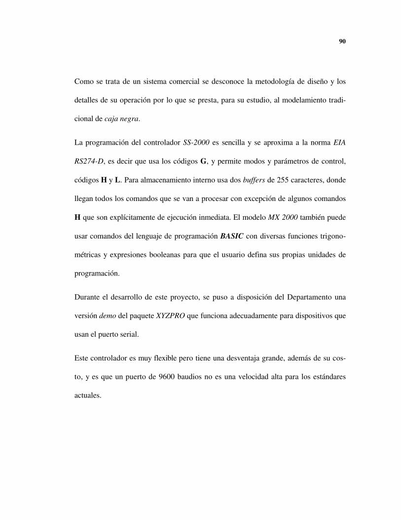
90
Como se trata de un sistema comercial se desconoce la metodología de diseño y los
detalles de su operación por lo que se presta, para su estudio, al modelamiento tradi-
cional de caja negra.
La programación del controlador SS-2000 es sencilla y se aproxima a la norma EIA
RS274-D, es decir que usa los códigos G, y permite modos y parámetros de control,
códigos H y L. Para almacenamiento interno usa dos buffers de 255 caracteres, donde
llegan todos los comandos que se van a procesar con excepción de algunos comandos
H que son explícitamente de ejecución inmediata. El modelo MX 2000 también puede
usar comandos del lenguaje de programación BASIC con diversas funciones trigono-
métricas y expresiones booleanas para que el usuario defina sus propias unidades de
programación.
Durante el desarrollo de este proyecto, se puso a disposición del Departamento una
versión demo del paquete XYZPRO que funciona adecuadamente para dispositivos que
usan el puerto serial.
Este controlador es muy flexible pero tiene una desventaja grande, además de su cos-
to, y es que un puerto de 9600 baudios no es una velocidad alta para los estándares
actuales.
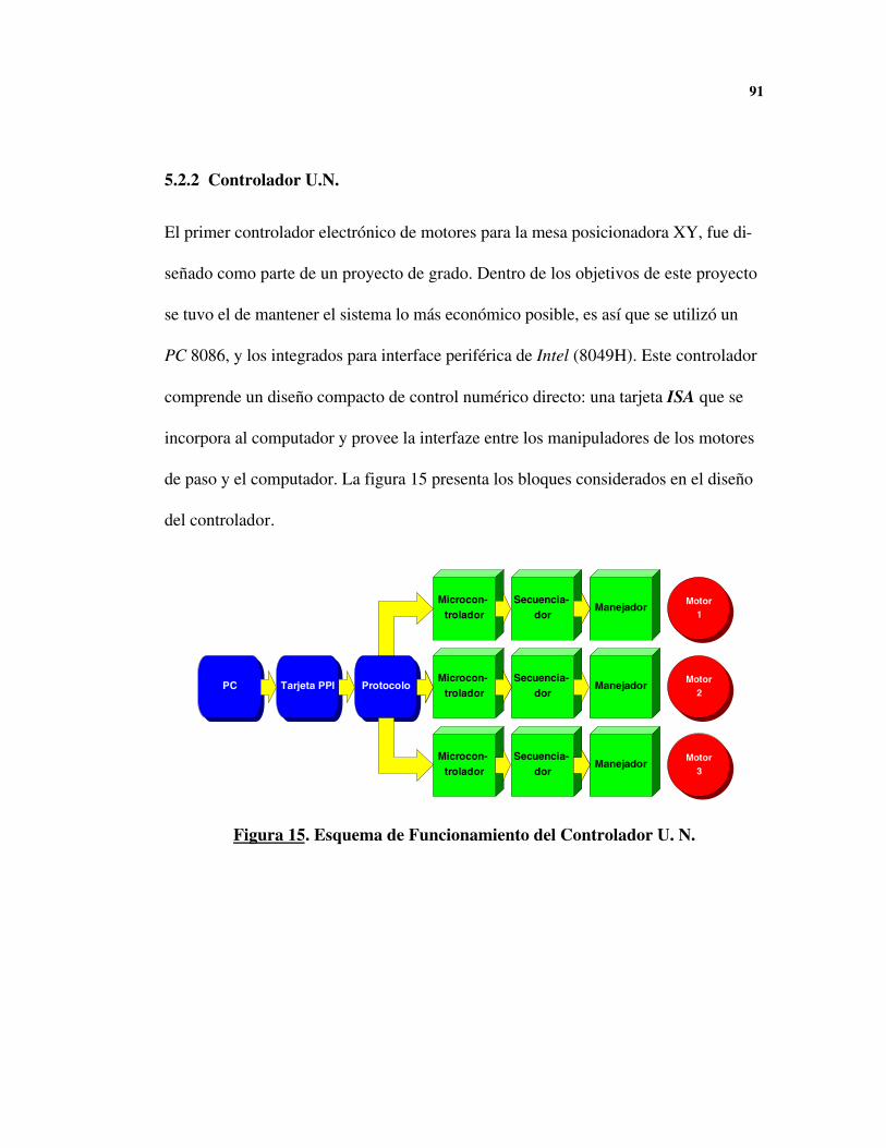
91
5.2.2 Controlador U.N.
El primer controlador electrónico de motores para la mesa posicionadora XY, fue di-
señado como parte de un proyecto de grado. Dentro de los objetivos de este proyecto
se tuvo el de mantener el sistema lo más económico posible, es así que se utilizó un
PC 8086, y los integrados para interface periférica de Intel (8049H). Este controlador
comprende un diseño compacto de control numérico directo: una tarjeta ISA que se
incorpora al computador y provee la interfaze entre los manipuladores de los motores
de paso y el computador. La figura 15 presenta los bloques considerados en el diseño
del controlador.
PC Tarjeta PPI Protocolo
Microcon- trolador
Microcon- trolador
Microcon- trolador
Secuencia- dor
Secuencia- dor
Secuencia- dor
Manejador
Manejador
ManejadorMotor
1
Motor 2
Motor 3
Figura 15. Esquema de Funcionamiento del Controlador U. N.
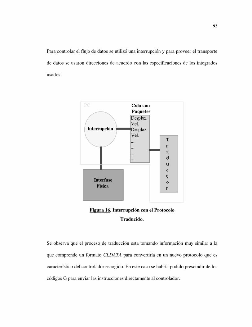
92
Para controlar el flujo de datos se utilizó una interrupción y para proveer el transporte
de datos se usaron direcciones de acuerdo con las especificaciones de los integrados
usados.
Figura 16. Interrupción con el Protocolo
Traducido.
Se observa que el proceso de traducción esta tomando información muy similar a la
que comprende un formato CLDATA para convertirla en un nuevo protocolo que es
característico del controlador escogido. En este caso se habría podido prescindir de los
códigos G para enviar las instrucciones directamente al controlador.

93
Comunicación
Comunicación
Manejador del Motor
Ejecución
Traducción
Interfase Hombre-Máquina Disco
Motor
Interfase F ís ica
PC
Microcontrolador
Figura 17. Configuración Usada en el
Controlador U. N.
Una forma alternativa de ver el controlador numérico se observa en la figura 17. En
este esquema se evidencia la importancia del protocolo escogido: el formato con que
se envían los datos al control numérico lleva de manera implícita los requerimientos de
los microcontroladores, y debe corresponder a las necesidades del usuario final. El
protocolo escogido por el grupo de trabajo en este caso consistió en paquetes com-

94
puestos por los datos de desplazamiento y velocidad en los tres motores. Estos datos
se conocen, en principio, en términos de unidades de unidades del sistema internacio-
nal, pero deben ser traducidas a unidades que entiendan los microcontroladores; es
decir, deben ser pasos o demoras del motor, y además se debe estipular el sentido de
giro. Esta conversión la hace el PC, no la tarjeta controladora, por lo que se realiza
antes de la comunicación.
La comunicación no requiere un sistema sofisticado para transportar la información: la
corrección de errores no es necesaria para este protocolo porque no hay distancia
apreciable entre los elementos y tampoco hay ruido considerable. De haberse escogido
usar los puertos seriales, se habría tenido que usar algún esquema para corregir los
errores inherentes a los sistemas de comunicaciones, y necesariamente se habría tenido
que aumentar la información transmitida con un código de verificación, disminuyendo
así la velocidad con que se alimenta el control numérico.
Después de leer el informe de grado, y observar las opciones de compilación, se dedu-
ce que las limitaciones de los computadores existentes durante la realización del pro-
yecto influyeron en el diseño del software de manera significativa. El computador que
se usa hoy en día en ese controlador es un 80286 con coprocesador numérico y moni-
tor monocromático, computador que es considerado obsoleto pero muy superior al
95
8086 en que se diseñó originalmente el software. Una leve mejora en rendimiento se
consigue recompilando el código fuente con el siguiente comando:
Directorio:\> tpc /B /$E- /$D- /$G+ cnc
El programa, cnc.pas, queda entonces optimizado para nuevas arquitecturas disponi-
bles: como mínimo un 80286 con coprocesador numérico.
Hay dos niveles de software que se deben considerar: Un nivel superior correspondien-
te a la interface hombre-máquina y la traducción de códigos G al formato usado en el
controlador, y un nivel básico encargado de enviar la información de velocidad y po-
sición a los controladores de los motores. El nivel superior se escribió en Turbo Pas-
cal con algunas rutinas en Assembler mientras que el nivel básico está conformado por
rutinas en lenguaje de máquina que están en una memoria Erasable Programable
Read Only Memory (EPROM) y se produjeron exclusivamente con lenguaje Assem-
bler.
Al pasar este programa de nivel superior por un conversor especial entre Pascal y C,
llamado p2c, sobresalió la existencia de código Assembler en prácticamente todas las
operaciones sobre la máquina de CN. El uso de Assembler, opción ofrecida por Turbo
Pascal, tiene como ventaja la sencillez para realizar operaciones de bajo nivel, y por
consiguiente una dramática mejora en la velocidad de ejecución. Desafortunadamente,
el código en assembler tiene efectos nocivos sobre la portabilidad del programa, es

96
decir, este programa no funcionará en arquitecturas distintas y se tendrían que hacer
modificaciones importantes para usarlo con un compilador distinto.
El controlador diseñado en la U. N. tiene grandes desventajas; no se controla el error
acumulado15 ni hay posibilidades de realimentación, pero también tiene grandes virtu-
des y cumple eficientemente la función para la cual fue diseñado; provee un manejo
eficiente de la mesa posicionadora. Se sale de los objetivos planteados un estudio de-
tallado de este controlador, pero se debe destacar que es el único sistema que posee-
mos que se puede desarmar, estudiar y probar sin restricciones.
Si comparamos el costo de este controlador con el costo de un equipo comercial de
similares características, podemos obtener una relación cercana a 1:10, por lo que se
puede concluir que vale la pena continuar esta línea de investigación.
15 Aparentemente el código para corregir el error mecánico no funciono adecuadamente y por eso el código co-
rrespondiente esta comentariado en el programa resultante.

EL SOFTWARE DE CONTROL
El sistema ideal debe resolver todas las necesidades de la unidad consola planteadas
por el grupo de trabajo de Michel Moreaux. Adicionalmente sería ideal proveer un
sistema genérico que permita la operación de todos los controladores numéricos dis-
ponibles y que soporte acceso desde una red de manufactura. No se tiene conocimien-
to de software con estas características, pero se sabe que de existir tendría un costo
elevado.
6.1 SELECCIÓN DEL AMBIENTE DE PROGRAMACIÓN
El mercado nacional tiene limitaciones en cuanto a los lenguajes de programación que
se pueden adquirir de acuerdo al Sistema Operativo sobre el cual correrá la aplicación.
En todo caso es importante tener en cuenta la portabilidad del programa, es decir, la

98
posibilidad de utilizar el mismo programa en otro sistema operativo, inclusive otra má-
quina, sin reescribirlo todo. Un lenguaje que permite una alta portabilidad es C: este
lenguaje viene con la mayoría de sistemas UNIX y está implementado en casi todos, si
no todos, los sistemas operativos. Una ventaja adicional del C es la posibilidad de ha-
cer manipulaciones de bajo nivel.
Una necesidad que surgió tempranamente fue la de usar una metodología orientada a
objetos para desarrollar el software. Hay diversos lenguajes que se prestan para traba-
jar con orientación a objetos, se destacan: SmallTalk, Simula, Modula, ADA y
LabView. Todos estos lenguajes son difíciles de conseguir localmente. Las implemen-
taciones modernas de los lenguajes tradicionales han optado por adoptar modificacio-
nes que faciliten este tipo de programación.
El lenguaje C, por si solo, no provee una estructura que permita usar OOP pero se han
desarrollado extensiones que permiten esta funcionalidad. Una de estas extensiones,
probablemente la más usada, es C++. Bjarne Stoustrup16 de los laboratorios AT&T
Bell desarrollo el lenguaje C++ con el objetivo de proveer un C mejor que el C. El re-
sultado final es un lenguaje en el que se puede usar código ANSI C y adicionalmente
se pueden definir y usar objetos.
16 STROUSTRUP BJARNE, The C++ Programming Language, Ed. Addison Wesley, Segunda Edición
99
El lenguaje C++ se escogió para el prototipo de esta implementación por ser muy co-
mún y por la posibilidad de seguir usando el código C indistintamente.
El sistema operativo más adecuado para desarrollar este tipo de aplicaciones es UNIX:
su ambiente gráfico permite portabilidad entre máquinas distintas, es multitarea, mul-
tiusuario, y además es posible conseguir implementaciones públicas de MicroMMS y la
suite de protocolos OSI. En el mundo UNIX no sólo hay muchos programas gratuitos
sino que el sistema operativo mismo se puede conseguir sin costo alguno.
Pese a las enormes ventajas que tiene UNIX, en nuestro medio el sistema operativo
más usado es MS-Windows y es poco viable, comercialmente, desarrollar el software
en un sistema distinto. Actualmente, solo Windows NT Workstation tiene una estabili-
dad suficiente para el trabajo continuo en una fábrica.
Visual Basic, otra herramienta que se estudió demostró ser mas fácil de manejar, pero
no proveía las opciones de control a bajo nivel que se requerían. Para efectos de la
implementación prototipo, se utilizó Visual C++, una implementación de C++ de Mi-
crosoft que provee bibliotecas especializadas (MFC) para el desarrollo de aplicaciones
gráficas que se planearon para permitir el acceso a 32 bits de los microprocesadores
actuales.
Con la definición del sistema operativo y el lenguaje de programación queda definido
un entorno de programación particular; se considera que en este ambiente se tienen
100
todas las facilidades, de alto y de bajo nivel, para realizar el desarrollo deseado de tal
forma que no es necesario recurrir a herramientas adicionales. No se descarta, sin em-
bargo, que sea deseable combinar el programa con otra utilidad escrita en Visual Ba-
sic.
6.2 DISEÑO DEL SOFTWARE
Claramente el problema de diseñar un software de control numérico requiere conocer
las necesidades del usuario final: la solución adecuada debe proveer la flexibilidad su-
ficiente para permitir que el software evolucione con las necesidades del cliente.
El software a diseñar debe soportar DNC, pero ante todo su estructura debe permitir
la implementación de las nuevas tecnologías que se han mencionado. Este problema
particular requiere, entonces, proporcionar un modelo de tamaño variable que esté en
capacidad de evolucionar de acuerdo a las necesidades del mercado.
La metodología seguida consistió en mantener el prototipo lo más sencillo posible para
después añadirle opciones más avanzadas. Esta metodología estuvo acorde con las ne-
cesidades actuales del Departamento de Mecánica ya que no se cuenta con una red de
manufactura en la cual se puedan realizar pruebas. El camino para la inclusión de una
101
red de este tipo, sin embargo, quedó abierto porque se obtuvieron algunos progra-
mas17 de libre distribución, y se reportaron al exterior los errores que se presentaron al
ponerlas a funcionar en algunas estaciones UNIX de la universidad.
6.2.1 Ventajas de la Programación Orientada a Objetos
La programación orientada a objetos (Object Oriented Programming, OOP), también
denominada programación por simulación, parte de definir unidades con identidad y
funciones propias llamadas objetos, y expresar las interacciones entre estos objetos en
el programa. La programación orientada a objetos se dio a conocer en el desarrollo de
ambientes gráficos, como el de Machintosh* , en que se modelan los elementos de
acuerdo a su función: carpetas, escritorios, canecas, etc...
El concepto de objeto es intuitivo y se presenta naturalmente en el problema estudia-
do: en esencia todos los bloques dentro de cada diagrama de este documento se pue-
den considerar objetos.
La ventaja al usar OOP radica no sólo en facilitar la interacción con el hombre en el
ambiente gráfico; también se mejora el mantenimiento del programa ya que es más
17 ISODE y MicroMMS se mencionaron en el cápitulo de Redes de Manufactura.
* Machintosh es una marca registrada de Apple Computer.

102
sencillo reparar, o actualizar, el código correspondiente a un elemento identificable y
no el conjunto de procedimientos resultantes en la programación tradicional.
Las herramientas básicas, ofrecidas por C++, que se usaron para obtener el modelo
deseado fueron la modularidad y la abstracción de la información
La modularidad consiste en la posibilidad de escribir toda la información relacionada
en una unidad independiente dentro del programa: se puede tener código para funcio-
nes relacionadas sin mezclarlo con el resto del programa. Esta característica se usó al
escribir la implementación de los dispositivos de manufactura en un archivo indepen-
diente: en el futuro, un implementador de dispositivos nuevos sabrá que en este archi-
vo encontrará toda la información que necesita y no la buscará desde el principio hasta
el final del programa.
La abstracción de la información se refiere a la posibilidad de escribir funciones que se
pueden usar en el resto del programa sin necesidad de describir los detalles internos de
la función: de esta manera se pueden hacer cambios sobre la función sin necesidad de
modificar todo el programa. C++ permite, adicionalmente, sobrecargar las funciones
de tal forma que si se necesita usar la una función para manipular información distinta
a la de otra función ya definida, el programa sabrá que función ejecutar de acuerdo a
los parámetros que se envíen. Si, por ejemplo, se usa una función para enviar números
a la pantalla y otra para enviar caracteres, basta ponerle el mismo nombre a las dos y el
103
computador decide que función usa de acuerdo a los valores que se den en tiempo de
ejecución.
6.2.2 Estructura del Programa
La metodología de Booch18 es una de las estrategias preferidas para diseñar software
con un enfoque orientado a objetos: aunque esta metodología no se siguió de manera
estricta se siguieron los lineamientos generales.
La primera etapa consistió en la identificación de los objetos presentes en el problema:
• El dispositivo de manufactura: debe recibir la información y procesarla, en reali-
dad se trabajará con un controlador de dispositivos. Hay una estrecha relación con
el VMD definido por MMS.
• El Controlador de Eventos: Es el encargado de coordinar las actividades de ma-
nufactura de acuerdo a los mensajes que le envían otros objetos.
• La consola: la unidad que interactúa directamente con el operario, comprende un
ambiente gráfico agradable y herramientas básicas de configuración.
18 Grady Booch, Object-oriented development, IEEE Transactions on Software Engineering, SE-12(2):211-221.
1986
104
Estos tres objetos constituyen el núcleo del software considerado: hay otros objetos
derivados del ambiente gráfico que se pueden considerar partes de la consola, como el
editor de codigo CNC, los botones de control y los cuadros de diálogo.
6.2.3 Consideraciones Técnicas
De los tres objetos considerados el usuario sólo necesita conocer la unidad consola: en
la medida de lo posible no se debe reportar el manejo interno a menos que ocurra un
error de ejecución. Los otros dos objetos, el controlador del dispositivo, y el controla-
dor de eventos son responsables del manejo en tiempo real del dispositivo, y pese a ser
transparentes para el usuario deben ser partes muy robustas.
Debido a las debilidades inherentes a Windows, y la mayoría de los sistemas operati-
vos, siempre existe la posibilidad de algún error en tiempo de ejecución, por este moti-
vo se prefirió proveer una consola muy primitiva y dejar la edición de código CNC a
editor especializados. Al independizar estas funciones mejora la confiabilidad porque
las acciones sobre el editor no afectarán la ejecución del proceso.
105
6.3 EL CONTROLADOR DE DISPOSITIVOS
De los dos dispositivos que se podían diseñar, un dispositivo serial para el controlador
MX-2000 y un controlador para el controlador U.N., se escogió escribir un controla-
dor serial genérico que sirva para controlar el MX-2000. Esta decisión se tomó por la
dificultad de rediseñar el software del controlador U.N. y por la poca normalización
que se manejó en el software de ese proyecto. Al escribir un software para el puerto
serial se cubre una variedad de dispositivos comerciales que incluye el MX-2000.
Un archivo de encabezado es un archivo que contiene la descripción del módulo pero
no tiene los detalles del codigo usado: es lo único que requiere saber un futuro usuario
del objeto. El encabezado del módulo de control por el puerto serial se presenta a
continuación (Figura 18). Se debe notar que, por su extensión, no se incluye el listado
completo del programa pero el código fuente se incluye en el disquete que acompaña
esta documentación.
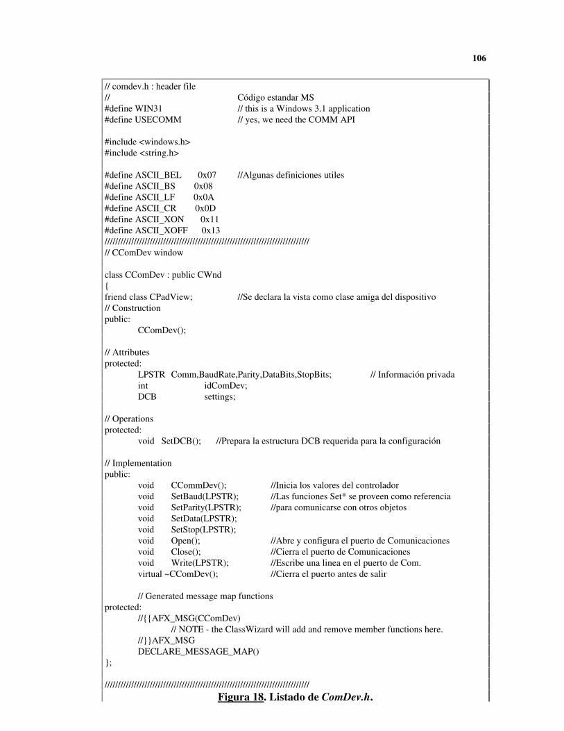
106
// comdev.h : header file// Código estandar MS#define WIN31 // this is a Windows 3.1 application#define USECOMM // yes, we need the COMM API
#include <windows.h>#include <string.h>
#define ASCII_BEL 0x07 //Algunas definiciones utiles#define ASCII_BS 0x08#define ASCII_LF 0x0A#define ASCII_CR 0x0D#define ASCII_XON 0x11#define ASCII_XOFF 0x13/////////////////////////////////////////////////////////////////////////////// CComDev window
class CComDev : public CWnd{friend class CPadView; //Se declara la vista como clase amiga del dispositivo// Constructionpublic:
CComDev();
// Attributesprotected:
LPSTR Comm,BaudRate,Parity,DataBits,StopBits; // Información privadaint idComDev;DCB settings;
// Operationsprotected:
void SetDCB(); //Prepara la estructura DCB requerida para la configuración
// Implementationpublic:
void CCommDev(); //Inicia los valores del controladorvoid SetBaud(LPSTR); //Las funciones Set* se proveen como referenciavoid SetParity(LPSTR); //para comunicarse con otros objetosvoid SetData(LPSTR);void SetStop(LPSTR);void Open(); //Abre y configura el puerto de Comunicacionesvoid Close(); //Cierra el puerto de Comunicacionesvoid Write(LPSTR); //Escribe una linea en el puerto de Com.virtual ~CComDev(); //Cierra el puerto antes de salir
// Generated message map functionsprotected:
//{{AFX_MSG(CComDev)// NOTE - the ClassWizard will add and remove member functions here.
//}}AFX_MSGDECLARE_MESSAGE_MAP()
};
/////////////////////////////////////////////////////////////////////////////Figura 18. Listado de ComDev.h.
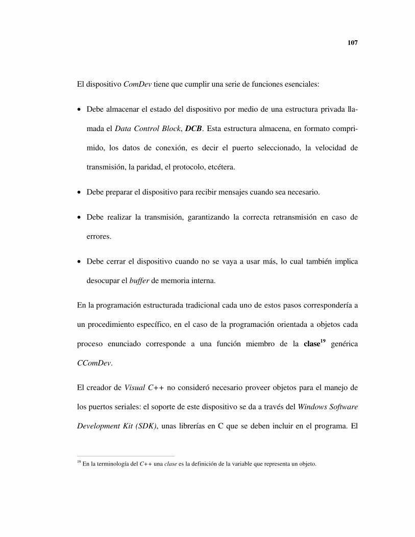
107
El dispositivo ComDev tiene que cumplir una serie de funciones esenciales:
• Debe almacenar el estado del dispositivo por medio de una estructura privada lla-
mada el Data Control Block, DCB. Esta estructura almacena, en formato compri-
mido, los datos de conexión, es decir el puerto seleccionado, la velocidad de
transmisión, la paridad, el protocolo, etcétera.
• Debe preparar el dispositivo para recibir mensajes cuando sea necesario.
• Debe realizar la transmisión, garantizando la correcta retransmisión en caso de
errores.
• Debe cerrar el dispositivo cuando no se vaya a usar más, lo cual también implica
desocupar el buffer de memoria interna.
En la programación estructurada tradicional cada uno de estos pasos correspondería a
un procedimiento específico, en el caso de la programación orientada a objetos cada
proceso enunciado corresponde a una función miembro de la clase19 genérica
CComDev.
El creador de Visual C++ no consideró necesario proveer objetos para el manejo de
los puertos seriales: el soporte de este dispositivo se da a través del Windows Software
Development Kit (SDK), unas librerías en C que se deben incluir en el programa. El
19 En la terminología del C++ una clase es la definición de la variable que representa un objeto.

108
software habría funcionado igual si se hubieran usado estas funciones directamente pe-
ro se prefirió unir todas estas funciones bajo un mismo objeto, de esta manera se le da
una identidad al dispositivo y se abre la posibilidad de usar una característica especial
de la programación orientada a objetos: la herencia.
La herencia permite, por ejemplo, definir una clase VMD que tiene valores y funcio-
nes que la identifican, y adicionalmente se puede derivar una clase CommDev que he-
reda las propiedades de la clase VMD y añade o retira algunas propiedades. De la clase
CommDev, a su vez, se puede derivar una clase MX_2000 que contenga las caracte-
rísticas adicionales de un controlador MX-2000 y utilice las propiedades del dispositi-
vo serial utilizando el código ya probado.
Esta metodología de diseño ahorra mucho tiempo a futuros implementadores porque
no tienen necesidad de rediseñar el código y sus adiciones correrán automáticamente.
Si se desea, por ejemplo, crear una clase ContUN para el controlador U.N. se puede
usar la clase VMD para derivar la nueva clase y se tendrá compatibilidad con varias
funciones ya escritas.
Otra ventaja de crear la clase CommDev fue la definición de una clase amiga para el
cuadro de diálogo de configuración. Una clase amiga es una clase que puede acceder
a los datos privados de una clase distinta. Ocultar la información es elegante y evita

109
accesos erróneos sobre variables restringidas pero en casos especiales, como el cambio
de configuración, es conveniente poder modificar datos privados de un objeto.
Figura 19. Cuadro de Diálogo para Configurar
el Puerto.
6.4 EL CONTROLADOR DE EVENTOS
La gran debilidad de OOP es el manejo en tiempo real: el enfoque de objetos no ga-
rantiza respuesta en un tiempo determinado. Windows maneja los procesos concurren-
tes dándoles tiempo cada vez que el programador envía una señal: la estrategia es en-
110
viar señales cada vez que se termine una labor predefinida. Se consideró que esta es-
trategia no era la adecuada para el problema estudiado porque implicaba darle la prio-
ridad a lo que hiciera el operario en la consola y no al proceso de transmisión.
En este punto, se optó por una solución primitiva pero práctica: mientras se transmite
no se puede hacer nada más. El microprocesador se dedica únicamente a realizar, lo
más eficazmente posible, la transmisión: de esta forma se consigue garantizar la
transmisión en tiempo real.
El controlador de eventos definido en MMS tiene sentido en cuanto hay varios usua-
rios, varios trabajos por realizar, o una red. El soporte de red MAP para Windows no
esta disponible y Windows sólo permite que un proceso a la vez acceda al dispositivo.
Ante éstas condiciones no es necesario implementar un controlador de eventos: con el
manejo interno de mensajes que provee el compilador de Visual C++ es suficiente. El
compilador de Visual C++ añade y retira el código de los mensajes automáticamente
cuando se usa el Class Wizard, una herramienta para organizar el programa
6.5 LA CONSOLA
Usualmente una consola provee una serie de comandos de control y un ambiente có-
modo para la manipulación de procesos que se desean transmitir. Aquí se debió tener

111
en cuenta las exigencias planteadas por el modelo Moreaux. Si bien se deseaba mante-
ner esta unidad muy sencilla, se implementaron las funciones básicas:
• Facilidades de carga y descarga de archivos externos CNC.
• Opciones para corregir, adicionar, o borrar partes del programa.
• Opción de cambiar la configuración del dispositivo
• Posilidad de acceder al resto del entorno y hacer intercambios de información con
otros programas.
En realidad la consola aprovecha los objetos disponibles en las Microsoft Foundation
Classes, MFC, del Visual C++ y tiene todas las funciones características del entorno
Windows: se pueden abrir varios documentos, cambiar el tipo de letra, imprimir, cor-
tar, pegar, etc. Cada opción es descrita en español cuando se va a seleccionar, y tam-
bién existe la alternativa de usar el teclado en vez del mouse.

112
6.6 FUNCIONAMIENTO DEL PROGRAMA
El programa se llamó DNCPad, ya que funciona similar a un editor de texto corriente
pero además ofrece acceso a un dispositivo de manufactura DNC. El manejo del dis-
positivo es transparente para el usuario, por lo que no se requiere una explicación de-
tallada del programa.
Figura 20. Imagen del Menu de Edición en la Aplicación.
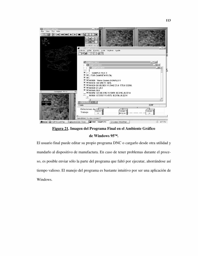
113
El usuario final puede editar su propio programa DNC o cargarlo desde otra utilidad y
mandarlo al dispositivo de manufactura. En caso de tener problemas durante el proce-
so, es posible enviar sólo la parte del programa que faltó por ejecutar, ahorrándose así
tiempo valioso. El manejo del programa es bastante intuitivo por ser una aplicación de
Windows.
Figura 21. Imagen del Programa Final en el Ambiente Gráfico
de Windows 95™™.

CONCLUSIONES
Considerando la bibliografía estudiada, la manufactura automatizada en la Universidad
Nacional presenta un atraso tecnológico de por lo menos cinco años frente a la tecno-
logía actual. Existen diversas causas para este atraso, pero sobresalen la poca demanda
de la industria nacional y la escasa inversión del estado en la investigación tecnológica.
Por supuesto, la Universidad Nacional refleja la realidad del país y una de sus misiones
es generar profesionales que se adapten bien al entorno en que éste se desarrolla: para
el estado carece de sentido invertir en profesionales que no serán contratados. La tec-
nología avanza muy rápidamente y las empresas se limitan a esperar los nuevos adelan-
tos provenientes del exterior; como resultado no existe una demanda interna de ma-
quinaria que justifique un alto desarrollo en manufactura automatizada. Del estudio
expuesto en el numeral 1.2 se deduce que la comunidad académica no está en capaci-
dad de lograr avances tecnológicos importantes si no cuenta con el apoyo decidido del
sector privado, y en particular del sector metalmecánico.
115
Otro factor que ha afectado el desarrollo tecnológico de la manufactura automatizada
en la Universidad Nacional es la demora con que la información llega al país. Hoy está
disponible en el país mucha información reciente relativa a la manufactura automatiza-
da, que no era posible conseguir hace unos años, pero aún hay factores coyunturales
que frenan el acceso a la información. Los avances en redes de computadores, las ba-
ses de datos en CDROM y la necesaria normalización de los procesos industriales han
hecho que sea posible reducir la brecha tecnológica entre los países desarrollados y los
subdesarrollados, pero la tecnología más reciente siempre permanece en las industrias
y universidades extranjeras hasta que alcanza una madurez que garantiza su comercia-
lización.
La creación del postgrado en manufactura automatizada es un signo alentador ante la
perspectiva de colaborar en el desarrollo industrial del país. Si bien el país estará obli-
gado a comprar tecnología del exterior por mucho tiempo, más importante que adqui-
rirla es saberla manejar con inteligencia para solucionar eficientemente las necesidades
de la industria. El postgrado puede forjar una cultura de industria automatizada que el
país requiere.
Las redes de manufactura surgen como una solución novedosa a las dificultades de
comunicación propias de una planta. Si bien las redes industriales sólo se encontraban
en empresas como General Motors, la tendencia mundial es aplicar la tecnología de la
116
red internet a nivel interno, consolidándose el concepto de una intranet. Es de espe-
rarse que estas intranets lleguen a formar parte directa del proceso de manufactura si-
guiendo las normas que se han establecido para redes MAP y TOP.
Los desarrollos anteriores en la Universidad Nacional, concretamente la mesa posicio-
nadora y el controlador numérico, demuestran que es viable hacer construcciones fun-
cionales en la universidad y es de esperarse que se logren diseños competitivos si se
logra coordinar todos los esfuerzos con una sola metodología. Desafortunadamente
los esfuerzos de los años recientes no han tenido siempre la misma orientación y las
conclusiones de un proyecto particular no son aplicables a los demás. Es claro que el
diseño de un centro de mecanizado es un proyecto a largo plazo que requiere la con-
currencia de diversas ramas de la ingeniería, por lo que la adopción de normas y una
adecuada documentación de cada subproyecto son las claves fundamentales del éxito.
Si bien las normas ISO no delimitan el proceso de diseño, dan unos requerimientos
básicos que deben tenerse en cuenta. Por ejemplo: la normatividad de los lenguajes
ISO-CNC, también denominados códigos G, se debió gobernar el desarrollo el contro-
lador numérico U.N., como el protocolo en que se almacena la información no es
acorde a la norma, los programas escritos para fabricar piezas con este controlador no
sirven para la máquina industrial convencional.
117
En general, los ambientes gráficos tienen una serie de ventajas en cuanto a flexibilidad
ya que permiten una interacción cercana entre todas las aplicaciones, de allí la tenden-
cia a preferirlos, pero también tienen un efecto nocivo sobre el rendimiento general del
equipo ya que exigen más recursos, y especialmente más tiempo de ejecución. Aunque
el costo de los equipos ha estado disminuyendo dramáticamente en los últimos años,
se debe tener cuidado en garantizar que el equipo y el sistema operativo puedan con-
trolar los procesos asignados en tiempo real. En el caso de Windows, la opción más
práctica es dedicar todo el tiempo del microprocesador a realizar los trabajos críticos,
en el caso de UNIX se puede usar el soporte de procesamiento concurrente para brin-
dar una solución más elegante.
La programación orientada a objetos, OOP, se plantea como la metodología más ade-
cuada para obtener diseños portables y fáciles de mantener. Se debe notar, sin embar-
go, que el manejo de funciones de bajo nivel y los procesos en tiempo real requieren
un tratamiento especial en tales ambientes. C++ brindó facilidades para programar
funciones de bajo nivel.
Al diseñar software de control numérico es necesario tener en cuenta la posibilidad de
hacer mejoras o modificaciones al software ya que la tecnología cambia rápidamente.
El programa de control DNCPad puede ampliarse, en un futuro, para soportar DCN
sin hacer cambios excesivos, ya que el modelo propuesto le permite al diseñador del

118
dispositivo definir las funciones básicas de comunicaciones de su dispositivo sin tener
que preocuparse por la interacción con el usuario. El diseñador del dispositivo debe
limitarse a escribir el código que envía la línea con comandos CNC al controlador nu-
mérico donde será procesada.
El costo de un programa comercial para control numérico es elevado, y su costo au-
menta de acuerdo a los dispositivos que se soportan. En estos programas no es posible
añadir más dispositivos ni hacer mejoras a medida que la tecnología avanza porque el
código fuente no está disponible, por lo que se demuestran enormes beneficios al dise-
ñar software genérico para controladores numéricos y hacerlo disponible en el medio
académico.
Un requisito importante para el software de control numérico es la posibilidad de inte-
ractuar con la demás aplicaciones del ambiente gráfico. El programa que se construyó,
DNCPad, permite intercambios de información con el editor de programas CNC de
XYZPRO y con las demás aplicaciones disponibles comercialmente.

ANEXO A.
RFC 1006 ISO Transport Service on top of the TCP V. 3
Network Working Group Marshall T. Rose, Dwight E. CassRequest for Comments: RFC 1006 Northrop Research and Technology CenterObsoletes: RFC 983 May 1987
ISO Transport Service on top of the TCPVersion: 3
Status of this Memo
This memo specifies a standard for the Internet community. Hosts on the Internet that choose to im-plement ISO transport services on top of the TCP are expected to adopt and implement this standard.TCP port 102 is reserved for hosts which implement this standard. Distribution of this memo is un-limited.
This memo specifies version 3 of the protocol and supersedes [RFC983]. Changes between the proto-col as described in Request for Comments 983 and this memo are minor, but are unfortunately in-compatible.
1. INTRODUCTION AND PHILOSOPHY
The Internet community has a well-developed, mature set of transport and internetwork protocols(TCP/IP), which are quite successful in offering network and transport services to end-users. TheCCITT and the ISO have defined various session, presentation, and application recommendationswhich have been adopted by the international community and numerous vendors. To the largest ex-tent possible, it is desirable to offer these higher level directly in the ARPA Internet, without disrup-

120
ting existing facilities. This permits users to develop expertise with ISO and CCITT applicationswhich previously were not available in the ARPA Internet. It also permits a more graceful conver-gence and transition strategy from TCP/IP-based networks to ISO-based networks in the medium-andlong-term.There are two basic approaches which can be taken when "porting" an ISO or CCITT application to aTCP/IP environment. One approach is to port each individual application separately, developing lo-cal protocols on top of the TCP. Although this is useful in the short-term (since special-purpose in-terfaces to the TCP can be developed quickly), it lacks generality.
A second approach is based on the observation that both the ARPA Internet protocol suite and theISO protocol suite are both layered systems (though the former uses layering from a more pragmaticperspective). A key aspect of the layering principle is that of layer-independence. Although this sec-tion is redundant for most readers, a slight bit of background material is necessary to introduce thisconcept.
Externally, a layer is defined by two definitions:
• a service-offered definition, which describes the services provided by the layer and the interfaces itprovides to access those services; and,
• a service-required definitions, which describes the services used by the layer and the interfaces it
uses to access those services.
Collectively, all of the entities in the network which co-operate to provide the service are known asthe service-provider. Individually, each of these entities is known as a service-peer.
Internally, a layer is defined by one definition:
• a protocol definition, which describes the rules which each service-peer uses when communicatingwith other service-peers.
Putting all this together, the service-provider uses the protocol and services from the layer belowto offer the its service to the layer above. Protocol verification, for instance, deals with proving thatthis in fact happens (and is also a fertile field for many Ph.D. dissertations in computer science).
The concept of layer-independence quite simply is:
• IF one preserves the services offered by the service-provider • THEN the service-user is completely naive with respect to the protocol which the service-peers use
For the purposes of this memo, we will use the layer-independence to define a Transport Service Ac-cess Point (TSAP) which appears to be identical to the services and interfaces offered by theISO/CCITT TSAP (as defined in [ISO8072]), but we will in fact implement the ISO TP0 protocol ontop of TCP/IP (as defined in [RFC793,RFC791]), not on top of the the ISO/CCITT network protocol.Since the transport class 0 protocol is used over the TCP/IP connection, it achieves identical functio-nality as transport class 4. Hence, ISO/CCITT higher level layers (all session, presentation, andapplication entities) can operate fully without knowledge of the fact that they are running on a

121
TCP/IP internetwork.
2. MOTIVATION
In migrating from the use of TCP/IP to the ISO protocols, there are several strategies that one mightundertake. This memo was written with one particular strategy in mind.
The particular migration strategy which this memo uses is based on the notion of gatewaying betweenthe TCP/IP and ISO protocol suites at the transport layer. There are two strong arguments for thisapproach:
1. Experience teaches us that it takes just as long to get good implementations of the lower levelprotocols as it takes to get implementations of the higher level ones. In particular, it has been ob-served that there is still a lot of work being done at the ISO network and transport layers. As a re-sult, implementations of protocols above these layers are not being aggressively pursued. Thus,something must be done "now" to provide a medium in which the higher level protocols can bedeveloped. Since TCP/IP is mature, and essentially provides identical functionality, it is an idealmedium to support this development.
2. Implementation of gateways at the IP and ISO IP layers are probably not of general use in the
long term. In effect, this would require each Internet host to support both TP4 and TCP. As such,a better strategy is to implement a graceful migration path from TCP/IP to ISO protocols for theARPA Internet when the ISO protocols have matured sufficiently.
Both of these arguments indicate that gatewaying should occur at or above the transport layer serviceaccess point. Further, the first argument suggests that the best approach is to perform the gatewayingexactly AT the transport service access point to maximize the number of ISO layers which can be de-veloped.
NOTE: This memo does not intend to act as a migration or intercept document. It is intendedONLY to meet the needs discussed above. However, it would not be unexpected that theprotocol described in this memo might form part of an overall transition plan. The des-cription of such a plan however is COMPLETELY beyond the scope of this memo.
Finally, in general, building gateways between other layers in the TCP/IP and ISO protocol suites isproblematic, at best.
To summarize: the primary motivation for the standard described in this memo is to facilitate theprocess of gaining experience with higher-level ISO protocols (session, presentation, and applica-tion). The stability and maturity of TCP/IP are ideal forproviding solid transport services independentof actual implementation.
3. THE MODEL

122
The [ISO8072] standard describes the ISO transport service definition, henceforth called TP.
ASIDE: This memo references the ISO specifications rather than the CCITT recom-mendations. The differences between these parallel standards are quite small, and can beignored, with respect to this memo, without loss of generality. To provide the reader withthe relationships:
Transport service [ISO8072] [X.214]Transport protocol [ISO8073] [X.224]
Session protocol [ISO8327] [X.225]
The ISO transport service definition describes the services offered by the TS-provider (transport ser-vice) and the interfaces used to access those services. This memo focuses on how the ARPA Trans-mission Control Protocol (TCP) [RFC793] can be used to offer the services and provide the interfaces.
For expository purposes, the following abbreviations are used:
TS-peer a process which implements the protocol described by this memo
TS-user a process talking using the services of a TS-peer
TS-provider the black-box entity implementing the protocol described by this memo
For the purposes of this memo, which describes version 2 of the TSAP protocol, all aspects of[ISO8072] are supported with one exception:
Quality of Service parameters
In the spirit of CCITT, this is left "for further study". A future version of the protocol will most likelysupport the QOS parameters for TP by mapping these onto various TCP parameters.
+-----------+ +-----------+| TS-user | | TS-user |+-----------+ +-----------+ | | | TSAP interface TSAP interface | | [ISO8072] | | |+----------+ ISO Transport Services on the TCP +----------+| client |-----------------------------------------| server |+----------+ (this memo) +----------+ | | | TCP interface TCP interface | | [RFC793] | | |

123
The ISO standards do not specify the format of a session port (termed a TSAP ID). This memo man-dates the use of the GOSIP specification [GOSIP86] for the interpretation of this field. (Please refer toSection 5.2, entitled "UPPER LAYERS ADDRESSING".)
Finally, the ISO TSAP is fundamentally symmetric in behavior. There is no underlying client/servermodel. Instead of a server listening on a well-known port, when a connection is established, the TS-provider generates an INDICATION event which, presumably the TS-user catches and acts upon.Although this might be implemented by having a server "listen" by hanging on the INDICATIONevent, from the perspective of the ISO TSAP, all TS-users just sit around in the IDLE state until theyeither generate a REQUEST or accept an INDICATION.
4. THE PRIMITIVES
The protocol assumes that the TCP[RFC793] offers the following service primitives:
Events
connected - open succeeded (either ACTIVE or PASSIVE)connect fails - ACTIVE open faileddata ready - data can be read from the connectionerrored - the connection has errored and is now closedclosed - an orderly disconnection has started Actionslisten on port - PASSIVE open on the given portopen port - ACTIVE open to the given portread data - data is read from the connectionsend data - data is sent on the connectionclose - the connection is closed (pending data is sent)
This memo describes how to use these services to emulate the following service primitives, which arerequired by [ISO8073]:
Events
N-CONNECT.INDICATION - An NS-user (responder) is notified that connection establishment is in progress
N-CONNECT.CONFIRMATION - An NS-user (responder) is notified that the connection has been established
N-DATA.INDICATION - An NS-user is notified that data can be read from the connection
N-DISCONNECT.INDICATION - An NS-user is notified that the connection is closed
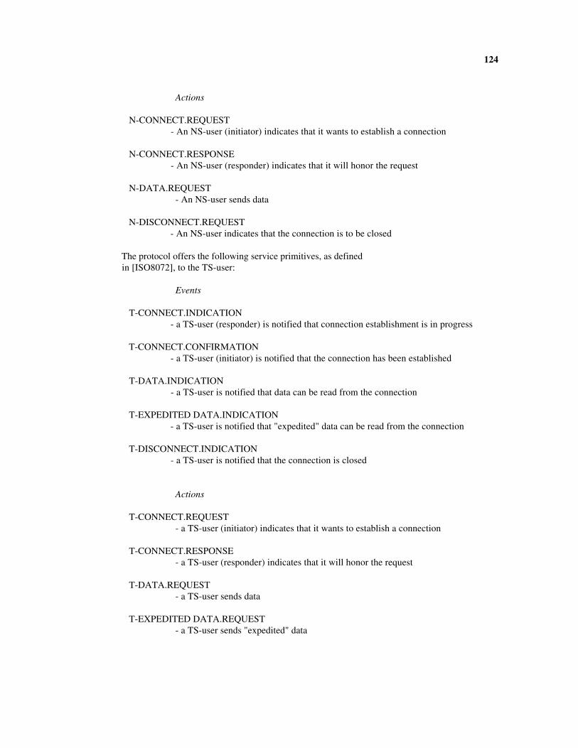
124
Actions
N-CONNECT.REQUEST - An NS-user (initiator) indicates that it wants to establish a connection
N-CONNECT.RESPONSE - An NS-user (responder) indicates that it will honor the request
N-DATA.REQUEST- An NS-user sends data
N-DISCONNECT.REQUEST - An NS-user indicates that the connection is to be closed
The protocol offers the following service primitives, as defined in [ISO8072], to the TS-user:
Events
T-CONNECT.INDICATION - a TS-user (responder) is notified that connection establishment is in progress
T-CONNECT.CONFIRMATION - a TS-user (initiator) is notified that the connection has been established
T-DATA.INDICATION - a TS-user is notified that data can be read from the connection
T-EXPEDITED DATA.INDICATION - a TS-user is notified that "expedited" data can be read from the connection
T-DISCONNECT.INDICATION - a TS-user is notified that the connection is closed
Actions
T-CONNECT.REQUEST- a TS-user (initiator) indicates that it wants to establish a connection
T-CONNECT.RESPONSE- a TS-user (responder) indicates that it will honor the request
T-DATA.REQUEST- a TS-user sends data
T-EXPEDITED DATA.REQUEST- a TS-user sends "expedited" data

125
T-DISCONNECT.REQUEST - a TS-user indicates that the connection is to be closed
5. THE PROTOCOL
The protocol specified by this memo is identical to the protocol for ISO transport class 0, with the fo-llowing exceptions:
- for testing purposes, initial data may be exchanged during connection establishment
- for testing purposes, an expedited data service is supported
- for performance reasons, a much larger TSDU size is supported
- the network service used by the protocol is provided by the TCP
The ISO transport protocol exchanges information between peers in discrete units of information ca-lled transport protocol data units (TPDUs). The protocol defined in this memo encapsulates theseTPDUs in discrete units called TPKTs. The structure of these TPKTs and their relationship toTPDUs are discussed in the next section.
PRIMITIVES
The mapping between the TCP service primitives and the service primitives expected by transportclass 0 are quite straight-forward:
network service TCP
CONNECTION ESTABLISHMENT
N-CONNECT.REQUEST open completes
N-CONNECT.INDICATION listen (PASSIVE open) finishes
N-CONNECT.RESPONSE listen completes
N-CONNECT.CONFIRMATION open (ACTIVE open) finishes
DATA TRANSFER
N-DATA.REQUEST send data
N-DATA.INDICATION data ready followed by read data
CONNECTION RELEASE
N-DISCONNECT.REQUEST close

126
N-DISCONNECT.INDICATION connection closes or errors
Mapping parameters is also straight-forward:
network service TCP
CONNECTION RELEASE
Called address server's IP address (4 octets)
Calling address client's IP address (4 octets)
all others ignored
DATA TRANSFER
NS-user data (NSDU) data
CONNECTION RELEASE
all parameters ignored
CONNECTION ESTABLISHMENT
The elements of procedure used during connection establishment are identical to those presented in[ISO8073], with three exceptions.
In order to facilitate testing, the connection request and connection confirmation TPDUs may ex-change initial user data, using the user data fields of these TPDUs.
In order to experiment with expedited data services, the connection request and connection confirma-tion TPDUs may negotiate the use of expedited data transfer using the negotiation mechanism speci-fied in [ISO8073] is used (e.g., setting the "use of transport expedited data transfer service" bit in the"Additional Option Selection" variable part). The default is not to use the transport expedited datatransfer service.
In order to achieve good performance, the default TPDU size is 65531 octets, instead of 128 octets.In order to negotiate a smaller (standard) TPDU size, the negotiation mechanism specified in[ISO8073] is used (e.g., setting the desired bit in the "TPDU Size" variable part).
To perform an N-CONNECT.REQUEST action, the TS-peer performs an active open to the desiredIP address using TCP port 102. When the TCP signals either success or failure, this results in an N-CONNECT.INDICATION action.
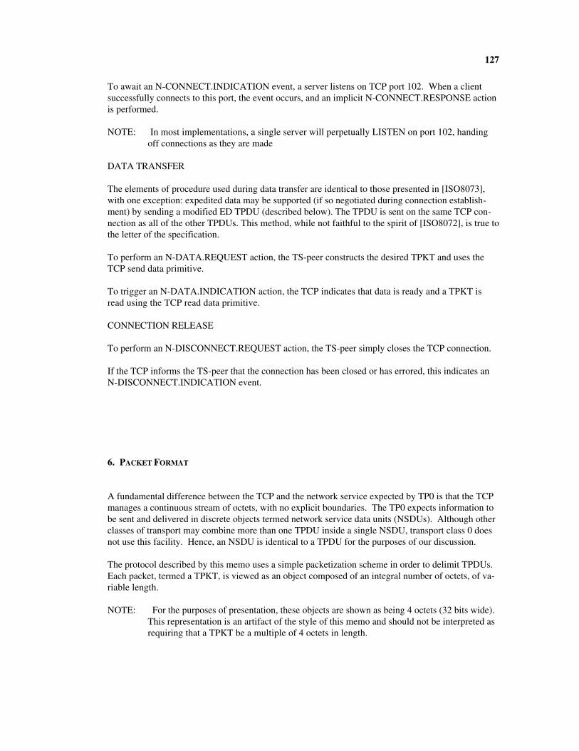
127
To await an N-CONNECT.INDICATION event, a server listens on TCP port 102. When a clientsuccessfully connects to this port, the event occurs, and an implicit N-CONNECT.RESPONSE actionis performed.
NOTE: In most implementations, a single server will perpetually LISTEN on port 102, handingoff connections as they are made
DATA TRANSFER
The elements of procedure used during data transfer are identical to those presented in [ISO8073],with one exception: expedited data may be supported (if so negotiated during connection establish-ment) by sending a modified ED TPDU (described below). The TPDU is sent on the same TCP con-nection as all of the other TPDUs. This method, while not faithful to the spirit of [ISO8072], is true tothe letter of the specification.
To perform an N-DATA.REQUEST action, the TS-peer constructs the desired TPKT and uses theTCP send data primitive.
To trigger an N-DATA.INDICATION action, the TCP indicates that data is ready and a TPKT isread using the TCP read data primitive.
CONNECTION RELEASE
To perform an N-DISCONNECT.REQUEST action, the TS-peer simply closes the TCP connection.
If the TCP informs the TS-peer that the connection has been closed or has errored, this indicates anN-DISCONNECT.INDICATION event.
6. PACKET FORMAT
A fundamental difference between the TCP and the network service expected by TP0 is that the TCPmanages a continuous stream of octets, with no explicit boundaries. The TP0 expects information tobe sent and delivered in discrete objects termed network service data units (NSDUs). Although otherclasses of transport may combine more than one TPDU inside a single NSDU, transport class 0 doesnot use this facility. Hence, an NSDU is identical to a TPDU for the purposes of our discussion.
The protocol described by this memo uses a simple packetization scheme in order to delimit TPDUs.Each packet, termed a TPKT, is viewed as an object composed of an integral number of octets, of va-riable length.
NOTE: For the purposes of presentation, these objects are shown as being 4 octets (32 bits wide).This representation is an artifact of the style of this memo and should not be interpreted asrequiring that a TPKT be a multiple of 4 octets in length.

128
A TPKT consists of two parts: a packet-header and a TPDU. The format of the header is constantregardless of the type of packet. The format of the packet-header is as follows:
where:
vrsn 8 bits
This field is always 3 for the version of the protocol described in this memo.
packet length 16 bits (min=7, max=65535)
This field contains the length of entire packet in octets, including packet-header. This permits a ma-ximum TPDU size of 65531 octets. Based on the size of the data transfer (DT) TPDU, this permits amaximum TSDU size of 65524 octets.
The format of the TPDU is defined in [ISO8073]. Note that only TPDUs formatted for transport class0 are exchanged (different transport classes may use slightly different formats).
To support expedited data, a non-standard TPDU, for expedited data is permitted. The format usedfor the ED TPDU is nearly identical to the format for the normal data, DT, TPDU. The only diffe-rence is that the value used for the TPDU's code is ED, not DT:
After the credit field (which is always ZERO on output and ignored on input), there is one additionalfield prior to the user data.
TPDU-NR and EOT 8 bits
Bit 7 (the high-order bit, bit mask 1000 0000) indicates the end of a TSDU. All other bits should beZERO on output and ignored on input.
Note that the TP specification limits the size of an expedited transport service data unit (XSDU) to 16octets.
0 1 2 30 1 2 3 4 5 6 7 8 9 0 1 2 3 4 5 6 7 8 9 0 1 2 3 4 5 6 7 8 9 0 1+-+-+-+-+-+-+-+-+-+-+-+-+-+-+-+-+-+-+-+-+-+-+-+-+-+-+-+-+-+-+-+-+| vrsn | reserved | packet length |+-+-+-+-+-+-+-+-+-+-+-+-+-+-+-+-+-+-+-+-+-+-+-+-+-+-+-+-+-+-+-+-+
0 1 2 30 1 2 3 4 5 6 7 8 9 0 1 2 3 4 5 6 7 8 9 0 1 2 3 4 5 6 7 8 9 0 1+-+-+-+-+-+-+-+-+-+-+-+-+-+-+-+-+-+-+-+-+-+-+-+-+-+-+-+-+-+-+-+-+| header length | code |credit |TPDU-NR and EOT| user data |+-+-+-+-+-+-+-+-+-+-+-+-+-+-+-+-+-+-+-+-+-+-+-+-+-+-+-+-+-+-+-+-+| ... | ... | ... | ... || ... | ... | ... | ... || ... | ... | ... | ... |+-+-+-+-+-+-+-+-+-+-+-+-+-+-+-+-+-+-+-+-+-+-+-+-+-+-+-+-+-+-+-+-+
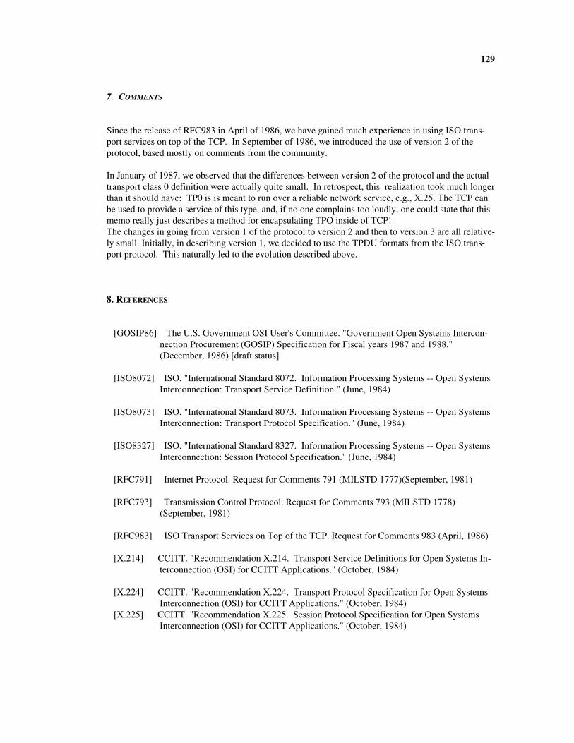
129
7. COMMENTS
Since the release of RFC983 in April of 1986, we have gained much experience in using ISO trans-port services on top of the TCP. In September of 1986, we introduced the use of version 2 of theprotocol, based mostly on comments from the community.
In January of 1987, we observed that the differences between version 2 of the protocol and the actualtransport class 0 definition were actually quite small. In retrospect, this realization took much longerthan it should have: TP0 is is meant to run over a reliable network service, e.g., X.25. The TCP canbe used to provide a service of this type, and, if no one complains too loudly, one could state that thismemo really just describes a method for encapsulating TPO inside of TCP!The changes in going from version 1 of the protocol to version 2 and then to version 3 are all relative-ly small. Initially, in describing version 1, we decided to use the TPDU formats from the ISO trans-port protocol. This naturally led to the evolution described above.
8. REFERENCES
[GOSIP86] The U.S. Government OSI User's Committee. "Government Open Systems Intercon-nection Procurement (GOSIP) Specification for Fiscal years 1987 and 1988."(December, 1986) [draft status]
[ISO8072] ISO. "International Standard 8072. Information Processing Systems -- Open SystemsInterconnection: Transport Service Definition." (June, 1984)
[ISO8073] ISO. "International Standard 8073. Information Processing Systems -- Open SystemsInterconnection: Transport Protocol Specification." (June, 1984)
[ISO8327] ISO. "International Standard 8327. Information Processing Systems -- Open SystemsInterconnection: Session Protocol Specification." (June, 1984)
[RFC791] Internet Protocol. Request for Comments 791 (MILSTD 1777)(September, 1981)
[RFC793] Transmission Control Protocol. Request for Comments 793 (MILSTD 1778)(September, 1981)
[RFC983] ISO Transport Services on Top of the TCP. Request for Comments 983 (April, 1986)
[X.214] CCITT. "Recommendation X.214. Transport Service Definitions for Open Systems In-terconnection (OSI) for CCITT Applications." (October, 1984)
[X.224] CCITT. "Recommendation X.224. Transport Protocol Specification for Open SystemsInterconnection (OSI) for CCITT Applications." (October, 1984)
[X.225] CCITT. "Recommendation X.225. Session Protocol Specification for Open SystemsInterconnection (OSI) for CCITT Applications." (October, 1984)

ANEXO B.
An Overview to the Manufacturing Message Specification
By:
Ralph Mackiewicz
(c) Copyright 1994. Ralph Mackiewicz. All Rights Reserved. Permission is hereby granted by theauthor for any individual or educational institution to copy and distribute this document freely provi-ded that 1) the document, or any copy thereof, is not used for commercial purposes, 2) is not copied,used or distributed by a commercial organization or company, and 3) that appropriate credit(including the copyright notice) be given in all reproductions and any other usage. Other rights maybe granted by written permission of the author.
DISCLAIMER: This document is provided "as is" without warranty of any kind. While the informa-tion contained herein is thought to be accurate at the time of publication, the author accepts no liabili-ty or responsibility of any kind for any use of this document.
OVERVIEW OF MMS:
What is MMS?
MMS (Manufacturing Message Specification) is an internationally standardized messaging system forexchanging real-time data and supervisory control information between networked devices and/orcomputer applications in a manner that is independent of: 1) the application function being perfor-med or 2) the developer of the device or application. MMS is an international standard(ISO 9506) that is developed and maintained by Technical Committee Number 184 (TC184), Indus-trial Automation, of the International Organization for Standardization (ISO).
The messaging services provided by MMS are generic enough to be appropriate for a wide variety ofdevices, applications, and industries. For instance, the MMS Read service allows an application ordevice to read a variable from another application or device. Whether the device is a ProgrammableLogic Controller (PLC) or a robot, the MMS services and messages are identical. Similarly, applica-tions as diverse as material handling, fault annunciation, energy management, electrical

117
power distribution control, inventory control, and deep space antenna positioning in industries as va-ried as automotive, aerospace, petro-chemical, electric utility, office machinery and space explorationhave put MMS to useful work.
The History of MMS
In the early 1980s a group of numerical controller (NC) vendors, machine builders and users workingunder the auspices of committee IE31 of the Electronic Industries Association (EIA) had developeddraft standard proposal #1393A titled "User Level Format and Protocol for Bi-directional Transfer ofDigitally Encoded Information in a Manufacturing Environment". When the General Motors Corpo-ration began its Manufacturing Automation Protocol (MAP) effort in 1980 they used the EIA-1393Adraft standard proposal as the basis for a more generic messaging protocol that could be used for NCs,programmable logic controllers (PLC), robots and other intelligent devices commonly used in a ma-nufacturing environments. The result was the Manufacturing Message Format Standard (MMFS).MMFS was used in the MAP Version 2 specifications published in 1984. During theinitial usage of MMFS it became apparent that a more rigorous messaging standard was needed.MMFS allowed too many choices for device and application developers. This resulted in severalmostly incompatible dialects of MMFS. Furthermore, MMFS did not provide sufficient functionalityto be useful for the Process Control Systems (PCS) found in continuous processing industries.With the objective of developing a generic and non-industry specific messaging system for communi-cations between intelligent manufacturing devices the MMS effort was begun under theauspices of Technical Committee Number 184, Industrial Automation, of the International Organiza-tion for Standardization (ISO).
The result was a standard based upon the Open Systems Interconnection (OSI) networking model ca-lled the Manufacturing Message Specification (MMS). A Draft International Standard (DIS) versionof MMS was published in December 1986 as ISO DIS 9506. The DIS version of MMS (Version 0)overcame the problems with MMFS but had not yet been advanced to the status of anInternational Standard (IS). Faced with a publication deadline of November 1988 the MAP technicalcommittees referenced the DIS version of MMS for the MAP V3.0 specification. In December 1988the IS version of MMS (Version 1) was released as ISO 9506 parts 1 and 2. It was not until after thedevelopment of backwards compatibility agreements by the National Institute of Standards and Te-chnology (NIST) that the IS version of MMS was referenced by the MAP V3.0 specifications.
The MMS Standard
The MMS standard (ISO 9506) is jointly managed by Technical Committee Number 184, IndustrialAutomation, of ISO and the International Electrotechnical Commission (IEC) and consists of two ormore parts (see "Companion Standards"). Parts 1 and 2 define what is referred to as the "core" ofMMS. Part 1 is the service specification. The service specification contains a definition of 1) theVirtual Manufacturing Device, 2) the services (or messages) exchanged between nodes on a network,and 3) the attributes and parameters associated with the VMD and services. Part 2 is the protocolspecification. The protocol specification defines the rules of communication which includes 1) the se-quencing of messages across the network, 2) the format (or encoding) of the messages, and 3) the in-teraction of the MMS layer with the other layers of the communications network. The protocol speci-fication utilizes a presentation layer standard called the Abstract Syntax Notation Number One(ASN.1 - ISO 8824) to specify the format of the MMS messages.
MMS provides a rich set of services for peer-to-peer real-time communications over a network. MMShas been used as a communication protocol for many common industrial control devices like CNCs,PLCs, robots. There are MMS applications in the electrical utility industry such as in Remote Termi-
118
nal Units (RTU), Energy Management Systems (EMS) and other Intelligent Electronic Devices (IED)like reclosers and switches. Most popular computing platforms have MMS connectivity available ei-ther from the computer manufacturer or via a third party. Some of the computer applications availa-ble include Application Programming Interfaces (API), graphical monitoring systems, gateways, anddrivers for spreadsheets, word processors, Application Enablers (A/Es) and relational data base ma-nagement systems (RDBMS). MMS implementations support a variety of communications links in-cluding Ethernet, Token Bus, RS-232C, OSI, TCP/IP, MiniMAP, FAIS, etc. and can connect to manymore types of systems using networking bridges, routers, and gateways.
Benefits of MMS
MMS provides benefits by lowering the cost of building and using automated systems. In particular,MMS is appropriate for any application that requires a common communications mechanism forperforming a diversity of communications functions related to real-time access and distribution ofprocess data and supervisory control. When looking at how the use of a common communicationsservice like MMS can benefit a particular system it is important to evaluate the three major affects ofusing MMS that can contribute to cost savings: 1) Interoperability, 2) Independence and 3) Access.
Interoperability is the ability of two or more networked applications to exchange useful supervisorycontrol and process data information between them without the user of the applications having tocreate the communications environment. While many communication protocols can provide some le-vel of interoperability, many of them are either too specific (to brand/type of application or device,network connectivity, or function performed -- see Independence below) or not specific enough(provide too many choices for how a developer uses the network).
Independence allows interoperability to be achieved independent of:
• The Developer of the Application. Other communications schemes are usually specific to a parti-cular brand (or even model in some cases) of application or device. MMS is defined by indepen-dent international standards bodies with participation from many leading industry experts andvendors.
• Network Connectivity. MMS becomes THE interface to the network for applications thereby iso-
lating the application from most of the non-MMS aspects of the network and how the networktransfers messages from one node to another.
• Function Performed. MMS provides a common communications environment independent of the
function performed. An inventory control application accesses production data contained in acontrol device in the exact same manner as an energy management system would read energy con-sumption data from the same device.
Data Access is the ability of networked applications to obtain the information required by an applica-tion. Although virtually any communications scheme can provide access to data at least insome minimal manner, they lack the other benefits of MMS particularly Independence (see above).
MMS is rigorous enough to minimize the differences between applications performing similar orcomplimentary functions while still being generic enough for many different kinds of applicationsand devices. Communications schemes that are not specific enough can result in applications that allperform similar or complimentary functions in different ways. The result is applications that cannotcommunicate with each other because the developers all made different choices when implementing.While many communications schemes only provide a mechanism for transmitting a sequence of bytes

119
(a message) across a network, MMS does much more. MMS also provides definition, structure andmeaning to the messages that significantly enhances the likelihood of two independently developedapplications interoperating. MMS has a rich set of features that facilitate the real-time distribution ofdata and supervisory control functions across a network in a client/server environment that can be assimple or sophisticated as the application warrants.
Justifying MMS
The real challenge in trying to develop a business justification for MMS (or any network investment)is in assigning value to the benefits given a specific business goal. In order to do this properly it isimportant to properly understand the relationship between the application functions, the connectivityfunctions and the business functions of the network.
In order to assign value to the use of MMS it is important to first understand the role that MMS playswith respect to applications. MMS, as an application layer protocol, provides applicationservices to the business functions, not connectivity services. It is common to view the network simplyas a mechanism to transfer messages (connectivity only). That view hides the value of the applicationfunctions because they become indistinguishable from the business applications which must thenprovide the network application functions. However, the costs are still there. Justifying MMS requi-res that the user recognize the value provided by the network application functions in facilitating inte-roperability, independence and access to data.
In some cases the benefit of the common communications infrastructure MMS provides is only reali-zed as the system is used, maintained, modified, and expanded over time. Therefore a justificationfor such a system must look at life cycle costs versus just the purchase price. It is also important notto underestimate the cost associated with developing, maintaining, and expanding theapplication functions that have to be created if MMS is not used. A key element in assigning value isunderstanding that the business functions are what provide value to the enterprise. The cost of thecustom network application functions directly reduces the amount of effort (i.e. cost) that can be pla-ced on developing, maintaining, and expanding the business functions. With MMS, the communica-tions infrastructure is built once and then re-used by all the business functions.
MMS Application Services
The key feature of MMS is the Virtual Manufacturing Device (VMD) model. The VMD model spe-cifies how MMS devices , also called servers, behave as viewed from an external MMS client appli-cation point of view. MMS allows any application or device to provide both client and server func-tions simultaneously. In general the VMD model defines:
• objects (e.g. variables) that are contained in the server, • the services that a client can use to access and manipulate these objects (e.g. read or write a va-
riable), and • the behavior of the server upon receipt of these service requests from clients.
The remainder of this overview of MMS will provide a summary of the objects defined by the VMDmodel and the MMS services provided to access and manipulate those objects. While the range ofobjects and services is broad, a given device or application need only implement whatever subset ofthese objects and services that are useful in that situation. A more detailed discussion of the MMS

120
VMD model and the various MMS objects and their services will be presented following this over-view.
VMD Object
The VMD itself can be viewed as an object to which all other MMS objects are subordinate (variables,domains, etc. are contained within the VMD). MMS provides services such as Status, UnsolicitedSta-tus, and Identify for obtaining information and status about the VMD. It also provides services likeGetNameList and Rename for managing and obtaining information about objects defined in theVMD.
Variable and Type Objects
MMS provides a comprehensive and flexible framework for exchanging variable information over anetwork. The MMS variable access model includes capabilities for named, unnamed (addressed), andnamed lists of variables. MMS also allows the type description of the variables to be manipulated asa separate MMS object (named type object). MMS variables can be simple (e.g. integer, boolean,floating point, string, etc.) or complex (e.g. arrays and structures). The services available to accessand manage MMS variable and type objects are very powerful and include services for:
Read and Write services allow MMS client applications to access the contents of Named Variables,Unnamed Variables, and Named Variable List objects.
The InformationReport service allows a server to report the contents of a variable to a remote client inan unsolicited manner.
Define, delete, and get attribute services are available for both variables and types to allow clients tomanage the variable access environment.
Service options allow groups of variables to be accessed in a single MMS request, allow large arraysand complex structures to be partially accessed (alternate access), and allow clients to recast variabletypes and complex structures to suit their needs (access by description).
Program Control Objects (Domains and Program Invocations)
The VMD execution model defines two objects for controlling the execution of programs within theVMD. A MMS domain is defined as an object that represents a resource within the VMD (e.g. thememory in which a program is stored). A program invocations is defined as a group of domains theexecution of which can be controlled and monitored. Some of the features of the services the VMDexecution model provides for MMS clients are:
• Services for commanding a VMD to upload/download their domains to/from a MMS client or filein a filestore system (either in the VMD or external to the VMD)
• Services for a VMD to request a domain upload/download from a client. • Start, Stop, Reset, Resume, and Kill services for controlling the execution of program invocations. • Services for deleting, creating, and obtaining the attributes of domains and program invocations. • State changes in program invocations can be linked to MMS events.

121
Event Objects
The MMS event management model defines several named objects consisting of:
• event conditions: an object that represents the state of an event (i.e. active or idle), • event actions: an object that consists of the action that should be taken by the VMD upon the oc-
currence of a change in state of the event condition, and • event enrollments: an object that represents which MMS clients should be notified upon a change
in state of an event condition.
The event management model provides a rich set of services for MMS clients:
Services for notifying clients about events and for clients to acknowledge these notifications.
Services for obtaining summaries of event conditions and event enrollments (called alarm summa-ries).
Services for deleting, defining, obtaining the status and attributes of, and controlling event condi-tions, event actions, and event enrollments.
Semaphore Objects
MMS semaphores are named objects that can be used to control access to other resources and objectswithin the VMD. For instance, a VMD that controls access to a setpoint (a variable) for a control lo-op could use semaphores to only allow one client at a time to be able to change the setpoint. (e.g. withthe MMS Write service). The MMS semaphore model defines two kinds of semaphores. Token se-maphores are used to represent a specific resource within the control of the VMD. Pool semaphoresconsist of one or more named tokens each representing a similar but distinct resource under the con-trol of the VMD. MMS provides semaphore services allow MMS clients to:
Take control of and relinquish the control of semaphores.
Define, delete, and get the attributes or status of semaphores.
Journal Objects
A MMS journal is a named object that represents a time based record, or log, of data. Each entry ina journal can contain the state of an event, the value of a variable, or character string data (called an-notation) that the VMD, or a MMS client, enters into the journal. Services available allow journals tocreated, read, deleted, and cleared (in whole or in part).
Operator Station Object
The operator station is an object that represents a means of communicating with the operator of theVMD via a keyboard and display. An Output service is available to display an alpha-numeric stringon a text display. An Input service is available to obtain alpha-numeric keyboard input with and wi-thout a text prompt on the display.
122
Files
An annex of MMS provides a simple set of services for transferring, renaming, and deleting files in aVMD. A FileDirectory service is provided to obtain a list of available files.
THE VIRTUAL MANUFACTURING DEVICE (VMD) MODEL
The primary goal of MMS was to specify a standard communications mechanism for devices andcomputer applications that would achieve a high level of interoperability. In order to achieve this goalit would be necessary for MMS to define much more than just the format of the messages to be ex-changed -- a common message format, or protocol, is only one aspect of achieving interoperability. Inaddition to protocol, the MMS standard also provides definitions for:
• Objects. MMS defines a set of common objects (e.g. variables, programs, events, etc.) and definesthe network visible attributes of those objects (e.g. name, value, type, etc.).
• Services. MMS defines a set of communications services (e.g. read, write, delete, etc.) for acces-
sing and managing these objects in a networked environment. • Behavior. MMS defines the network visible behavior that a device should exhibit when processing
these services.
This definition of objects, services, and behavior comprises a comprehensive definition of how devi-ces and applications communicate that MMS calls the Virtual Manufacturing Device (VMD) model.The VMD model only specifies the network visible aspects of communications. The internal detail ofhow a real device implements the VMD model (i.e. the programming language, operating system,CPU type, input/output (I/O) systems, etc.) are not specified by MMS. By focusing only on thenetwork visible aspects of a device, the VMD model is specific enough to provide a high level of inte-roperability while still being general enough to allow innovation in application/device implementa-tion and making MMS suitable for application across a range of industries and devices types.
A key aspect of the VMD model is the client/server relationship between networked applicationsand/or devices. A server is a device or application that contains a VMD and its objects (variables,etc.). A client is a networked application (or device) that asks for data or an action from the server. Ina very general sense, a client is a network entity that issues MMS service requests to a server. A ser-ver is a network entity that responds to the MMS requests of a client. While MMS defines theservices for both clients and servers, the VMD model defines the network visible behavior of serversonly.
Many MMS applications and MMS compatible devices provide both MMS client and server func-tions. The VMD model would only define the behavior of the server functions of those applications.Any MMS application or device that provides MMS server functions must follow the VMD modelfor all the network visible aspects of the server application or device. MMS clients are only requiredto conform to rules governing message format or construction and sequencing of messages (the proto-col).
"Real" and "Virtual" Devices and Objects

123
There is a distinction between a real device (e.g. a PLC, CNC, or robot) and the real objects containedin it (e.g. variables, programs, etc.) and the virtual device and objects defined by the VMD model.Real devices and objects have peculiarities (a.k.a. product features) associated with them that are uni-que to each brand of device or application. Virtual devices and objects conform to the VMD modeland are independent of brand, language, operating system, etc. Each developer of a MMS serverdevice or MMS server application is responsible for "hiding" the details of their real devices and ob-jects, by providing an executive function. The executive function translates the real devices and ob-jects into the virtual ones defined by the VMD model when communicating with MMS client appli-cations and devices. Because MMS clients always interact with the virtual device and objects definedby the VMD model, the client applications are isolated from the specifics of the real devicesand objects. A properly designed MMS client application can communicate with many differentbrands and types of devices in the same manner because the details of the real devices and objects arehidden from the MMS client by the executive function in each VMD. This virtual approach to des-cribing server behavior does not constrain the development of innovative devices and product featuresand improvements. The MMS VMD model places constraints only on the network visible aspects ofthe virtual devices and objects, not the real ones.
MMS Device and Object Modeling
The implementor of the executive function (the application or device developer) must decide how to"model" the real objects as virtual objects. The manner in which these objects are modeled is criticalto achieving interoperability between clients and servers among many different developers. Inappro-priate or incorrect modeling can lead to an implementation that is difficult to use or difficult to inte-roperate with.
For instance, take the situation of a PLC that contains a ladder program (a real object). The MMSimplementor (the designer of the executive function) wishes to allow external client applications tocopy the program from the PLC to another computer. For the purposes of this example we shallassume that the MMS VMD model gives the implementor the choice of modeling the ladder programobject as a variable or domain object (both virtual objects). The choice of which virtual object to mapto the real ladder program object is critical because MMS provides a set of services to manipulate va-riables that are quite different from the services used to manipulate domains. Variables can be readindividually or in a list of typed data. Domains can be copied in whole only. If the ladder program ismodeled as a MMS variable it makes the task of performing a simple copying of the program com-plex because the nature of the ladder program data (typically a large block of contiguous memory)would result in an extremely large variable that would be difficult to access easily. If the ladder pro-gram is modeled as a domain, there are specific MMS services provided for uploading and downloa-ding the large blocks of untyped data typical of ladder programs. An incorrect modeling choice canmake the real object difficult to access.
In some cases it makes sense to represent the same real object with two different MMS objects. Forinstance, a large block of variables may also be modeled as a domain. This would provide the MMSclient the choice of services to use when accessing the data. The variable services would give access tothe individual elements in the block. The domain services would allow the entire block to beread/uploaded or written/downloaded as an element of a program invocation (see the batch controllerexample of page 16).
Companion Standards
In many cases the relationship between the real objects and the virtual objects can be standardized fora particular class of device or application (e.g. a PLC or PCS). Developers and users of these real de-
124
vices can define more precisely how MMS is applied to a particular class of device or application.The result is a companion standard. In general, companion standards perform the following func-tions:
• Define the mapping of real objects to the VMD model for a particular class of device. For instan-ce, the companion standard for process control systems would define the relationships betweenreal objects such as setpoints, alarm limits and proportional-integral-derivative (PID) control lo-ops to MMS domains, variables, and program invocations.
• Provide additional definition of the behavioral characteristics of the VMD model for particular
classes of devices. For instance, the actions a PLC takes when receiving a MMS Start or Stop ser-vice request is very different from the actions taken by robots to these same service requests.
• Define additional network visible attributes for common objects. For example, the PLC companion
standard defines additional status information for use in the MMS Status and UnsolicitedStatusservices.
• Define additional objects and services that are unique to a particular class of device. The robot
companion standard contains a definition of the VMDStop service different from the core MMSStop service.
• Define object naming and usage conventions for a particular class of device. For instance, stan-
dardized names and other naming conventions for common objects.
A companion standard, after proceeding through all the committees and work needed to become anISO international standard, becomes a companion of the MMS standard as an additional part. Therobot companion standard is ISO 9506 part 3, the NC companion standard will be ISO 9506 part 4,the PLC companion standard will be ISO 9506 part 5, and the PCS companion standard will be ISO9506 part 6.
The reader should be aware that, for most systems, companion standards are not necessary even whenusing devices for which companion standards exist. The core MMS services defined in parts 1 and 2of MMS provides sufficient standardization to achieve interoperability in most cases. Furthermore,aspects of the companion standards such as object naming, usage, and modeling conventions can beused in a core MMS application without having to implement the entire companion standard.
MMS Objects
MMS defines a variety of objects that are found in many typical devices and applications requiringreal-time communications. A list of these objects is given below. For each object there are correspon-ding MMS services that let client applications access and manipulate those objects. The model forthese objects and the services available are described in more detail later.
- VMD. The device itself is an object
- Domain. Represents a resource (e.g. a program) within the VMD.
- Program Invocation. A runnable program consisting of one or more domains.
- Variable. An element of typed data (e.g. integer, floating point, array, etc.)

125
- Type. A description of the format of a variable's data.
- Named Variable List. A list of variables that is named as a list.
- Semaphore. An object used to control access to a shared resource.
- Operator Station. A display and keyboard for use by an operator.
- Event Condition. An object that represents the state of an event.
- Event Action. Represents the action taken when an event condition changes state.
- Event Enrollment. Which network application to notify when an event condition changes state.
- Journal. A time based record of events and variables.
- File. A file in a filestore or fileserver.
- Transaction. Represents an individual MMS service request. Not a named object.
Object Attributes and Scope
Associated with each object are a set of attributes that describe that object. MMS objects have a nameattribute and other attributes that vary from object to object. Variables have attributes like, name, va-lue, type, etc. while other objects, program invocations for instance, have attributes like name andcurrent state.
Subordinate objects exist only within the scope of another object. For instance, all other objects aresubordinate to, or contained within, the VMD itself. Some objects, such as the operator station objectfor example, may be subordinate only to the VMD. Some objects by be contained within other objectssuch as variables contained within a domain. This attribute of an object is called its scope. The ob-ject's scope also reflects the lifetime of an object. An object's scope may be defined to be:
- VMD-Specific. The object has meaning and exists across the entire VMD (is subordinate to theVMD). The object exists as long as the VMD exists.
- Domain-Specific. The object is defined to be subordinate to a particular domain. The object willexist only as long as the domain exists.
- Application-Association-Specific. Also referred to as AA-Specific. The object is defined by theclient over a specific application association and can only be used by that specific client. Theobject exists as long as the association between the client and server exists.
The name of a MMS object must also reflect the scope of the object. For instance, the object name fora domain-specific variable must not only specify the name of the variable within that domain but alsothe name of the domain. Names of a given scope must be unique. For instance, the name of a variablespecific to a given domain must be unique for all domain specific variables in that domain. Some ob-jects, such as variables, are capable of being defined with any of the scopes described above. Others,like semaphores for example, cannot be defined to be AA-specific. Still others, like operator stations
126
for example, are only defined as VMD-specific. When an object like a domain is deleted, all the ob-jects subordinate to that domain must also be deleted.
The VMD Object
The VMD itself is also an object and has attributes associated with it. Some of the network visibleattributes for a VMD are:
- Capabilities. A capability of a VMD is a resource or capacity defined by the real device. There canbe more than one capability to a VMD. The capabilities are represented by a sequence ofcharacter strings. The capabilities are defined by the implentor of the VMD and providesuseful information about the real device or application.
- Logical Status. Logical status refers to the status of the MMS communication system for the VMDwhich can be:
STATE-CHANGES-ALLOWED, NO-STATE-CHANGES-ALLOWED or ONLY-SUPPORT-SERVICES-ALLOWED.
- Physical Status. Physical status refers to the status of all the capabilities taken as a whole which canbe equal to:
OPERATIONAL, PARTIALLY-OPERATIONAL, INOPERABLE or NEEDS-COMMISSIONING.
VMD Support Services
- Status. This confirmed service is used by a client to obtain the logical and physical status of theVMD. The Status and UnsolicitedStatus service also supports access to implementationspecific status information (called local detail) defined by the implementor of the VMD.
- UnsolicitedStatus. This unconfirmed service is used by a server (VMD) to report its status to a clientunsolicited by the client.
- GetNameList. This confirmed service allows a client to obtain a list of named objects defined withinthe VMD.
- Identify. This confirmed service allows the client to obtain information about the MMS implemen-tation such as the vendor's name, model number, and revision level.
THE VMD EXECUTION MODEL
The VMD model has a flexible execution model that provides a definition of how the execution ofprograms by the MMS server can be controlled. Central to this execution model are the definitions ofthe domain and program invocation objects.
Domains
The MMS domain is a named MMS object that is a representation of some resource within the realdevice. This resource can be anything that is appropriately represented as a contiguous block of un-typed data (referred to as load data). In many typical applications domains are used to represent areasof memory in a device. For instance, a PLC's ladder program memory is typically represented as a
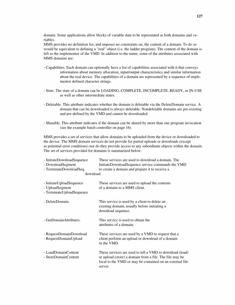
127
domain. Some applications allow blocks of variable data to be represented as both domains and va-riables.MMS provides no definition for, and imposes no constraints on, the content of a domain. To do sowould be equivalent to defining a "real" object (i.e. the ladder program). The content of the domain isleft to the implementor of the VMD. In addition to the name, some of the attributes associated withMMS domains are:
- Capabilities. Each domain can optionally have a list of capabilities associated with it that conveysinformation about memory allocation, input/output characteristics and similar informationabout the real device. The capabilities of a domain are represented by a sequence of imple-mentor defined character strings.
- State. The state of a domain can be LOADING, COMPLETE, INCOMPLETE, READY, or IN-USEas well as other intermediate states.
- Deletable. This attribute indicates whether the domain is deletable via the DeleteDomain service. Adomain that can be downloaded is always deletable. Nondeletable domains are pre-existingand pre-defined by the VMD and cannot be downloaded.
- Sharable. This attribute indicates if the domain can be shared by more than one program invocation(see the example batch controller on page 16).
MMS provides a set of services that allow domains to be uploaded from the device or downloaded tothe device. The MMS domain services do not provide for partial uploads or downloads (exceptas potential error conditions) nor do they provide access to any subordinate objects within the domain.The set of services provided for domains is summarized below:
- InitiateDownloadSequence These services are used to download a domain. The- DownloadSegment InitiateDownloadSequence service commands the VMD- TerminateDownloadSeq. to create a domain and prepare it to receive a download.
- InitiateUploadSequence These services are used to upload the contents- UploadSegment of a domain to a MMS client.- TerminateUploadSequence
- DeleteDomain. This service is used by a client to delete an existing domain, usually before initiating a download sequence.
- GetDomainAttributes. This service is used to obtain the attributes of a domain.
- RequestDomainDownload These services are used by a VMD to request that a- RequestDomainUpload client perform an upload or download of a domain in the VMD.
- LoadDomainContent These services are used to tell a VMD to download (load)- StoreDomainContent or upload (store) a domain from a file. The file may be local to the VMD or may be contained on an external file server.
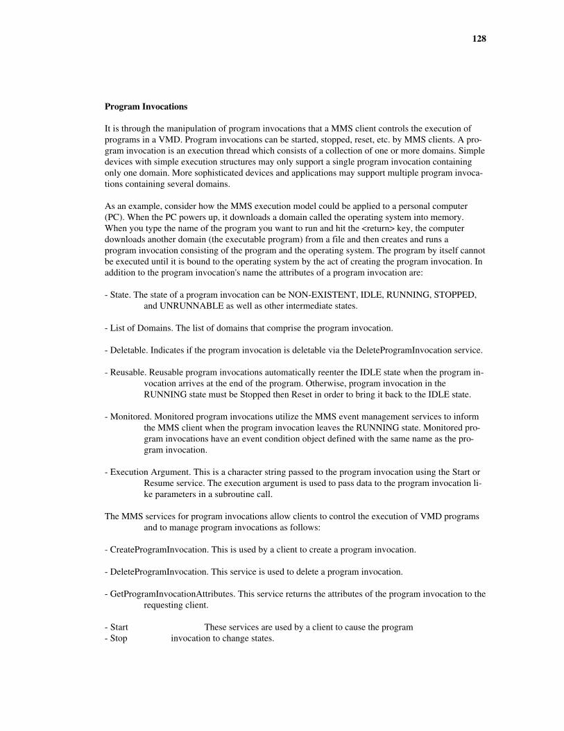
128
Program Invocations
It is through the manipulation of program invocations that a MMS client controls the execution ofprograms in a VMD. Program invocations can be started, stopped, reset, etc. by MMS clients. A pro-gram invocation is an execution thread which consists of a collection of one or more domains. Simpledevices with simple execution structures may only support a single program invocation containingonly one domain. More sophisticated devices and applications may support multiple program invoca-tions containing several domains.
As an example, consider how the MMS execution model could be applied to a personal computer(PC). When the PC powers up, it downloads a domain called the operating system into memory.When you type the name of the program you want to run and hit the <return> key, the computerdownloads another domain (the executable program) from a file and then creates and runs aprogram invocation consisting of the program and the operating system. The program by itself cannotbe executed until it is bound to the operating system by the act of creating the program invocation. Inaddition to the program invocation's name the attributes of a program invocation are:
- State. The state of a program invocation can be NON-EXISTENT, IDLE, RUNNING, STOPPED,and UNRUNNABLE as well as other intermediate states.
- List of Domains. The list of domains that comprise the program invocation.
- Deletable. Indicates if the program invocation is deletable via the DeleteProgramInvocation service.
- Reusable. Reusable program invocations automatically reenter the IDLE state when the program in-vocation arrives at the end of the program. Otherwise, program invocation in theRUNNING state must be Stopped then Reset in order to bring it back to the IDLE state.
- Monitored. Monitored program invocations utilize the MMS event management services to informthe MMS client when the program invocation leaves the RUNNING state. Monitored pro-gram invocations have an event condition object defined with the same name as the pro-gram invocation.
- Execution Argument. This is a character string passed to the program invocation using the Start orResume service. The execution argument is used to pass data to the program invocation li-ke parameters in a subroutine call.
The MMS services for program invocations allow clients to control the execution of VMD programsand to manage program invocations as follows:
- CreateProgramInvocation. This is used by a client to create a program invocation.
- DeleteProgramInvocation. This service is used to delete a program invocation.
- GetProgramInvocationAttributes. This service returns the attributes of the program invocation to therequesting client.
- Start These services are used by a client to cause the program- Stop invocation to change states.

129
- Reset- Resume- Kill
THE VARIABLE ACCESS MODEL
MMS Variables
A real variable is an element of typed data that is contained within a VMD. A MMS variable is avirtual object that represents a mechanism for MMS clients to access the real variable. Thedistinction between the real variable (which contains the value) and the virtual variable (which repre-sents the access path to the variable) is important. When a MMS variable is deleted, onlythe access to the variable is deleted, not the actual real variable. When a MMS variable is created it isthe access path that is created, not the real variable. MMS defines two types of virtual objects for des-cribing variable access:
- Unnamed Variable Object. An unnamed variable object describes the access to the real variable byusing a device specific address. MMS includes unnamed variable objects primarily for compatibilitywith older devices that are not capable of supporting names. An unnamed variable object is a directmapping to the underlying real variable that is located at the specified address. The attributes of theunnamed variable object are:
- Address. This is the key attribute of the unnamed variable object.
- MMS Deletable. This attribute is always FALSE for an unnamed variable object. Unnamed variableobjects cannot be deleted because they are a direct representation of the "real" variable loca-ted at a specific address in the VMD.
- Type Description. This attribute describes the type (format and range of (values) of the variable.
- Named Variable Object. The named variable object describes the access to the real variable by usinga MMS object name. MMS clients need only know the name of the object in order to accessit. Remember that the name of a MMS variable also specifies the scope (see page 12) of theobject. In addition to the name a named variable object has the following attributes:
- MMS Deletable. This attribute indicates if access to the variable can be deleted via the DeleteVa-riableAccess service.
- Type Description. This attribute describes the type (format and range of values) of the variable.
- Access Method. If the access method is PUBLIC, it means that the underlying address of the na-med variable object is visible to the MMS Client. In this case the same variable can be ac-cessed as an unnamed variable object.
Addresses
A MMS variable address can take on one of several forms. Which specific form that is used by aspecific VMD, and the specific conventions used by that address form, is determined by the imple-mentor of the VMD based upon what is most appropriate for that device. The possible forms for aMMS variable address are:
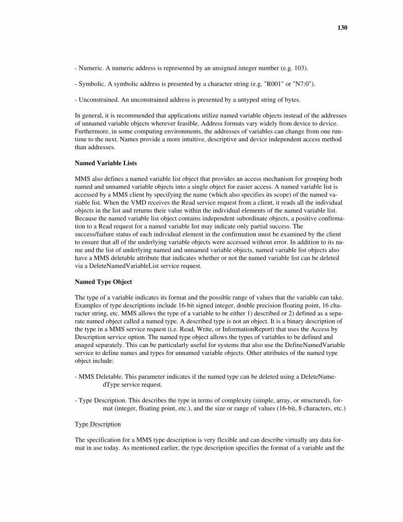
130
- Numeric. A numeric address is represented by an unsigned integer number (e.g. 103).
- Symbolic. A symbolic address is presented by a character string (e.g. "R001" or "N7:0").
- Unconstrained. An unconstrained address is presented by a untyped string of bytes.
In general, it is recommended that applications utilize named variable objects instead of the addressesof unnamed variable objects wherever feasible. Address formats vary widely from device to device.Furthermore, in some computing environments, the addresses of variables can change from one run-time to the next. Names provide a more intuitive, descriptive and device independent access methodthan addresses.
Named Variable Lists
MMS also defines a named variable list object that provides an access mechanism for grouping bothnamed and unnamed variable objects into a single object for easier access. A named variable list isaccessed by a MMS client by specifying the name (which also specifies its scope) of the named va-riable list. When the VMD receives the Read service request from a client, it reads all the individualobjects in the list and returns their value within the individual elements of the named variable list.Because the named variable list object contains independent subordinate objects, a positive confirma-tion to a Read request for a named variable list may indicate only partial success. Thesuccess/failure status of each individual element in the confirmation must be examined by the clientto ensure that all of the underlying variable objects were accessed without error. In addition to its na-me and the list of underlying named and unnamed variable objects, named variable list objects alsohave a MMS deletable attribute that indicates whether or not the named variable list can be deletedvia a DeleteNamedVariableList service request.
Named Type Object
The type of a variable indicates its format and the possible range of values that the variable can take.Examples of type descriptions include 16-bit signed integer, double precision floating point, 16 cha-racter string, etc. MMS allows the type of a variable to be either 1) described or 2) defined as a sepa-rate named object called a named type. A described type is not an object. It is a binary description ofthe type in a MMS service request (i.e. Read, Write, or InformationReport) that uses the Access byDescription service option. The named type object allows the types of variables to be defined andanaged separately. This can be particularly useful for systems that also use the DefineNamedVariableservice to define names and types for unnamed variable objects. Other attributes of the named typeobject include:
- MMS Deletable. This parameter indicates if the named type can be deleted using a DeleteName-dType service request.
- Type Description. This describes the type in terms of complexity (simple, array, or structured), for-mat (integer, floating point, etc.), and the size or range of values (16-bit, 8 characters, etc.)
Type Description
The specification for a MMS type description is very flexible and can describe virtually any data for-mat in use today. As mentioned earlier, the type description specifies the format of a variable and the
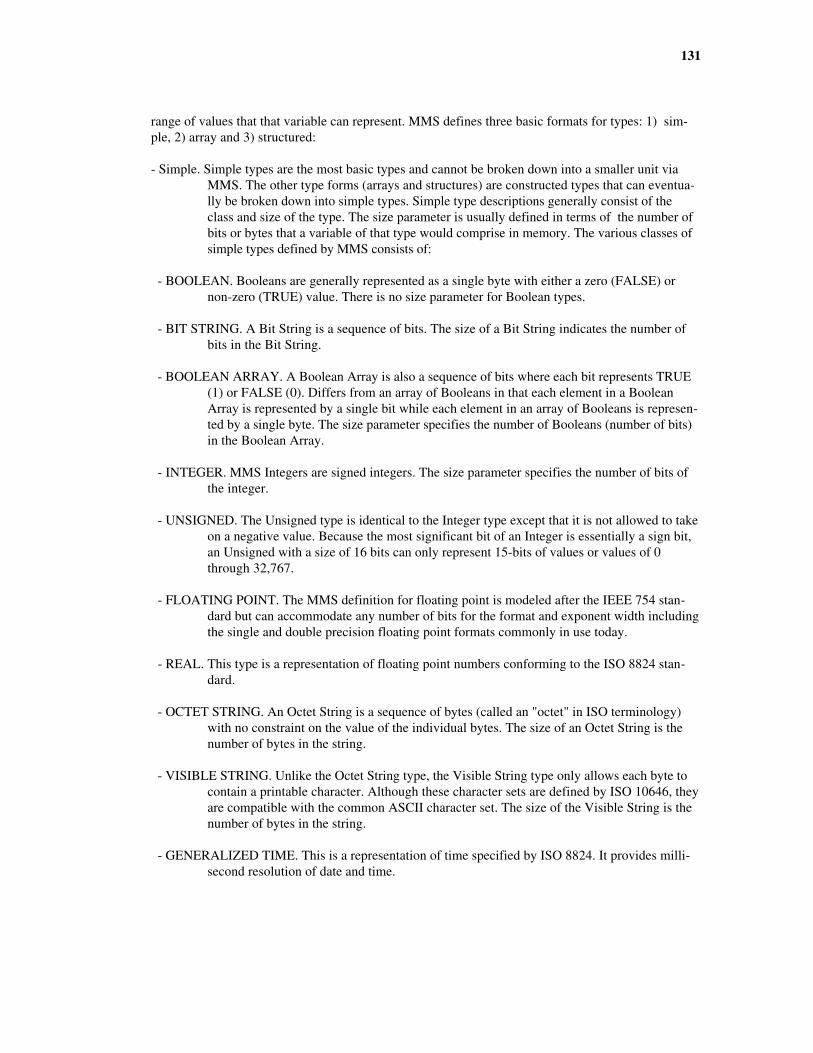
131
range of values that that variable can represent. MMS defines three basic formats for types: 1) sim-ple, 2) array and 3) structured:
- Simple. Simple types are the most basic types and cannot be broken down into a smaller unit viaMMS. The other type forms (arrays and structures) are constructed types that can eventua-lly be broken down into simple types. Simple type descriptions generally consist of theclass and size of the type. The size parameter is usually defined in terms of the number ofbits or bytes that a variable of that type would comprise in memory. The various classes ofsimple types defined by MMS consists of:
- BOOLEAN. Booleans are generally represented as a single byte with either a zero (FALSE) ornon-zero (TRUE) value. There is no size parameter for Boolean types.
- BIT STRING. A Bit String is a sequence of bits. The size of a Bit String indicates the number ofbits in the Bit String.
- BOOLEAN ARRAY. A Boolean Array is also a sequence of bits where each bit represents TRUE(1) or FALSE (0). Differs from an array of Booleans in that each element in a BooleanArray is represented by a single bit while each element in an array of Booleans is represen-ted by a single byte. The size parameter specifies the number of Booleans (number of bits)in the Boolean Array.
- INTEGER. MMS Integers are signed integers. The size parameter specifies the number of bits ofthe integer.
- UNSIGNED. The Unsigned type is identical to the Integer type except that it is not allowed to takeon a negative value. Because the most significant bit of an Integer is essentially a sign bit,an Unsigned with a size of 16 bits can only represent 15-bits of values or values of 0through 32,767.
- FLOATING POINT. The MMS definition for floating point is modeled after the IEEE 754 stan-dard but can accommodate any number of bits for the format and exponent width includingthe single and double precision floating point formats commonly in use today.
- REAL. This type is a representation of floating point numbers conforming to the ISO 8824 stan-dard.
- OCTET STRING. An Octet String is a sequence of bytes (called an "octet" in ISO terminology)with no constraint on the value of the individual bytes. The size of an Octet String is thenumber of bytes in the string.
- VISIBLE STRING. Unlike the Octet String type, the Visible String type only allows each byte tocontain a printable character. Although these character sets are defined by ISO 10646, theyare compatible with the common ASCII character set. The size of the Visible String is thenumber of bytes in the string.
- GENERALIZED TIME. This is a representation of time specified by ISO 8824. It provides milli-second resolution of date and time.
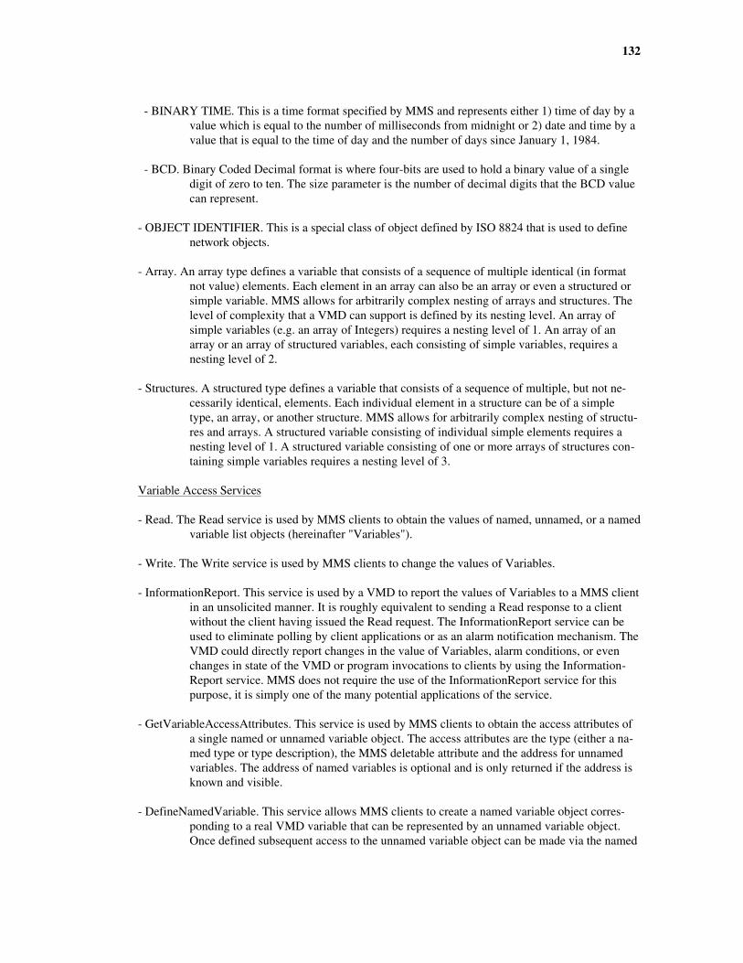
132
- BINARY TIME. This is a time format specified by MMS and represents either 1) time of day by avalue which is equal to the number of milliseconds from midnight or 2) date and time by avalue that is equal to the time of day and the number of days since January 1, 1984.
- BCD. Binary Coded Decimal format is where four-bits are used to hold a binary value of a singledigit of zero to ten. The size parameter is the number of decimal digits that the BCD valuecan represent.
- OBJECT IDENTIFIER. This is a special class of object defined by ISO 8824 that is used to definenetwork objects.
- Array. An array type defines a variable that consists of a sequence of multiple identical (in formatnot value) elements. Each element in an array can also be an array or even a structured orsimple variable. MMS allows for arbitrarily complex nesting of arrays and structures. Thelevel of complexity that a VMD can support is defined by its nesting level. An array ofsimple variables (e.g. an array of Integers) requires a nesting level of 1. An array of anarray or an array of structured variables, each consisting of simple variables, requires anesting level of 2.
- Structures. A structured type defines a variable that consists of a sequence of multiple, but not ne-cessarily identical, elements. Each individual element in a structure can be of a simpletype, an array, or another structure. MMS allows for arbitrarily complex nesting of structu-res and arrays. A structured variable consisting of individual simple elements requires anesting level of 1. A structured variable consisting of one or more arrays of structures con-taining simple variables requires a nesting level of 3.
Variable Access Services
- Read. The Read service is used by MMS clients to obtain the values of named, unnamed, or a namedvariable list objects (hereinafter "Variables").
- Write. The Write service is used by MMS clients to change the values of Variables.
- InformationReport. This service is used by a VMD to report the values of Variables to a MMS clientin an unsolicited manner. It is roughly equivalent to sending a Read response to a clientwithout the client having issued the Read request. The InformationReport service can beused to eliminate polling by client applications or as an alarm notification mechanism. TheVMD could directly report changes in the value of Variables, alarm conditions, or evenchanges in state of the VMD or program invocations to clients by using the Information-Report service. MMS does not require the use of the InformationReport service for thispurpose, it is simply one of the many potential applications of the service.
- GetVariableAccessAttributes. This service is used by MMS clients to obtain the access attributes ofa single named or unnamed variable object. The access attributes are the type (either a na-med type or type description), the MMS deletable attribute and the address for unnamedvariables. The address of named variables is optional and is only returned if the address isknown and visible.
- DefineNamedVariable. This service allows MMS clients to create a named variable object corres-ponding to a real VMD variable that can be represented by an unnamed variable object.Once defined subsequent access to the unnamed variable object can be made via the named
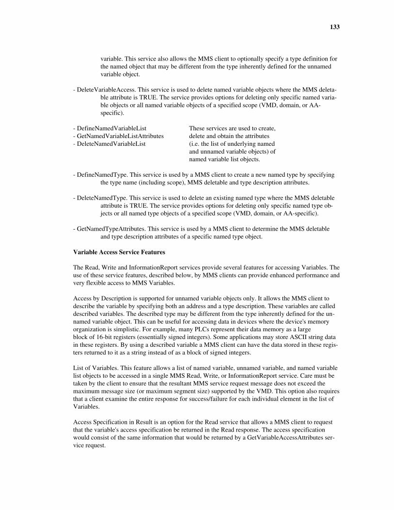
133
variable. This service also allows the MMS client to optionally specify a type definition forthe named object that may be different from the type inherently defined for the unnamedvariable object.
- DeleteVariableAccess. This service is used to delete named variable objects where the MMS deleta-ble attribute is TRUE. The service provides options for deleting only specific named varia-ble objects or all named variable objects of a specified scope (VMD, domain, or AA-specific).
- DefineNamedVariableList These services are used to create,- GetNamedVariableListAttributes delete and obtain the attributes- DeleteNamedVariableList (i.e. the list of underlying named and unnamed variable objects) of named variable list objects.
- DefineNamedType. This service is used by a MMS client to create a new named type by specifyingthe type name (including scope), MMS deletable and type description attributes.
- DeleteNamedType. This service is used to delete an existing named type where the MMS deletableattribute is TRUE. The service provides options for deleting only specific named type ob-jects or all named type objects of a specified scope (VMD, domain, or AA-specific).
- GetNamedTypeAttributes. This service is used by a MMS client to determine the MMS deletableand type description attributes of a specific named type object.
Variable Access Service Features
The Read, Write and InformationReport services provide several features for accessing Variables. Theuse of these service features, described below, by MMS clients can provide enhanced performance andvery flexible access to MMS Variables.
Access by Description is supported for unnamed variable objects only. It allows the MMS client todescribe the variable by specifying both an address and a type description. These variables are calleddescribed variables. The described type may be different from the type inherently defined for the un-named variable object. This can be useful for accessing data in devices where the device's memoryorganization is simplistic. For example, many PLCs represent their data memory as a largeblock of 16-bit registers (essentially signed integers). Some applications may store ASCII string datain these registers. By using a described variable a MMS client can have the data stored in these regis-ters returned to it as a string instead of as a block of signed integers.
List of Variables. This feature allows a list of named variable, unnamed variable, and named variablelist objects to be accessed in a single MMS Read, Write, or InformationReport service. Care must betaken by the client to ensure that the resultant MMS service request message does not exceed themaximum message size (or maximum segment size) supported by the VMD. This option also requiresthat a client examine the entire response for success/failure for each individual element in the list ofVariables.
Access Specification in Result is an option for the Read service that allows a MMS client to requestthat the variable's access specification be returned in the Read response. The access specificationwould consist of the same information that would be returned by a GetVariableAccessAttributes ser-vice request.

134
Alternate Access allows a MMS client to 1) partially access only specified elements contained in alarger arrayed and/or structured variable, and 2) rearrange the ordering of the elements contained instructured variables.
THE EVENT MANAGEMENT MODEL
In a real sense an event, or an alarm, is easy to define. Most people have an intuitive feel for what cancomprise an event within their own area of expertise. For instance, in a process control application itis common for a control system to generate an alarm when the process variable (e.g. temperature)exceeds a certain preset limit called the high alarm threshold. In a power distribution application analarm might be generated when the difference in the phase angle of the current and voltage wave-forms of a power line exceeds a certain number of degrees. The MMS event management model pro-vides a framework for accessing and managing the network communication aspects ofthese kinds of events. This is accomplished by defining three named objects that represent 1) the stateof an event (event condition), 2) who to notify about the occurrence of an event (event enrollment)and 3) the action that the VMD should take upon the occurrence of an event (event action).
For many applications, the communication of alarms can be implemented by using MMS servicesother than the event management services. For instance, a simple system can notify a MMS clientabout the fact that a process variable has exceeded some preset limit by sending the process variable'svalue to a MMS client using the InformationReport service. Other schemes using other MMS servicesare also possible. When the application is more complex and requires a more rigorous definition ofthe event environment in order to ensure interoperability, the MMS event management model shouldbe used.
Event Condition Object
A MMS event condition object is a named object that represents the current state of some real condi-tion within the VMD. It is important to note that MMS does not define the VMD action (orprogramming) that causes a change in state of the event condition. In the process control example gi-ven above, an event condition might reflect an IDLE state for when the process variable was not ex-ceeding the value of the high alarm threshold and an ACTIVE state when the process variable didexceed the limit. MMS does not explicitly define the mapping between the high alarm limit and thestate of the event condition. Even if the high alarm limit is represented by a MMS variable, MMSdoes not define the necessary configuration or programming needed to create the mapping betweenthe high alarm limit and the state of the event condition. From the MMS point of view, the change instate of the event condition is caused by some autonomous action on the part of the VMD that is notdefined by MMS. The MMS event management model defines two classes of event conditions:
- Network Triggered. A network triggered event condition is triggered when a MMS client specifica-lly triggers it using the TriggerEvent service request. Network triggered events do not havea state (their state is always DISABLED). They are useful for allowing a MMS client tocontrol the execution of event actions and the notifications of event enrollments.
- Monitored. A monitored event condition has a state attribute that the VMD sets based upon somelocal autonomous action. Monitored event conditions can have a Boolean variable associa-ted with them that is used by the VMD to evaluate the state. The VMD periodically evalua-tes this variable. If the variable is evaluated as TRUE, the VMD sets the event condition

135
state to ACTIVE. When the Boolean variable is evaluated as FALSE, the VMD sets theevent condition state to IDLE. Event conditions that are created as a result of a CreatePro-gramInvocation request with the Monitored attribute TRUE, are monitored event condi-tions but they do not have an associated Boolean variable.
In addition to the name of the event condition (an object name that also reflects its scope) and its class(NETWORK TRIGGERED or MONITORED), MMS defines the following attributes for bothnetwork triggered and monitored event conditions:
- MMS Deletable. This attribute indicates if the event condition can be deleted by using a DeleteE-ventCondition service request.
- State. This attribute reflects the state of the event condition and can be IDLE, ACTIVE, orDISABLED. Network triggered events are always DISABLED.
- Priority. This attributed reflects the relative priority of an event condition object with respect to allother defined event condition objects. Priority is a relative measure of the VMD's proces-sing priority when it comes to evaluating the state of the event condition as well as the pro-cessing of event notification procedures that are invoked when the event condition changesstate. A value of zero (0) is the highest priority. A value of 127 is the lowest priority. Avalue of 64 is the "normal" priority.
- Severity. This attribute reflects the relative severity of an event condition object with respect to allother defined event condition objects. Severity is a relative measure of the affect that achange in state of the event condition can have on the VMD. A value of zero (0) is the hi-ghest severity. A value of 127 is the lowest. A value of 64 is for event conditions with"normal" severity.
Additionally, MMS also defines the following attributes for Monitored event conditions only:
- Monitored Variable. This is a reference to the underlying Boolean variable whose value the VMDevaluates in determining the state of an event condition. It can be either a named or unna-med variable object. If it is a named object it must be a variable with the same name (andscope) of the event condition. If the event condition object is locally defined or it was defi-ned via a CreateProgramInvocation request with the monitored attribute TRUE, then thevalue of the monitored variable reference would be equal to UNSPECIFIED. If the monito-red variable is deleted, then the value of this reference would be UNDEFINED and theVMD should disable its event notification procedures for this event condition.
- Enabled. This attribute reflects whether a change in the value of the monitored variable (or the stateof the associated program invocation if applicable) should cause the VMD to process theevent notification procedures for the event condition (TRUE) or not (FALSE). A client candisable an event condition by changing this attribute via an AlterEventConditionMonito-ring service request.
- Alarm Summary Reports. This attribute indicates whether (TRUE) or not (FALSE) the event condi-tion should be included in alarm summary reports in response to a GetAlarmSummaryRe-port service request.

136
- Evaluation Interval. This attribute specifies the maximum amount of time, in milliseconds, betweensuccessive evaluations of the event condition by the VMD. The VMD may optionally allowclients to change the evaluation interval.
- Time of Last Transition to Active These attributes contain either- Time of Last Transition to Idle the time of day or a time sequence number of the last state transitions of the event condition. If the event condition has never been in the IDLE or ACTIVE state, then the value of the corresponding attribute shall be UNDEFINED.
Event Condition Services
- DefineEventCondition These services are used by MMS- DeleteEventCondition clients to create event condition- GetEventConditionAttributes objects, to delete event condition objects (if the MMS Deletable attribute is TRUE) and to obtain the static attributes of an existing event condition object respectively.
- ReportEventConditionStatus. This service allows a MMS client to obtain the dynamic status of theevent condition object including its state, the number of event enrollments enrolled in theevent condition, whether it is enabled or disabled, and the time of the last transitions to theactive and idle states.
- AlterEventConditionMonitoring. This service allows the MMS client to alter the priority, enable ordisable the event condition, enable or disable alarm summary reports and to change theevaluation interval if the VMD allows the evaluation interval to be changed.
- GetAlarmSummary. This service allows a MMS client to obtain event condition status and attributeinformation about groups of event conditions. The client can specify several filters for de-termining which event conditions to include in an alarm summary.
Event Actions
An event action is a named MMS object that represents the action that the VMD will take when thestate of an event condition changes. An event action is optional. When omitted, the VMD would exe-cute its event notification procedures without processing an event action. An event action, when used,is always defined as a confirmed MMS service request. The event action is attached or linked with anevent condition when an event enrollment is defined. For example, an event action mightbe a MMS Read request. If this event action is attached to an event condition (by being referenced inan event enrollment), when the event condition changes state and the event condition is enabled, theVMD would execute this Read service request just as if it had been received from a client. Except thatthe Read response (either positive or negative) is included in the EventNotification service requestthat is sent to the MMS client defined for the event enrollment. A confirmed service request must beused (i.e. Start, Stop, Read, etc.). Unconfirmed services (e.g. InformationReport, UnsolicitedStatus,and EventNotification) and other services that must be used in conjunction with other services (e.g.
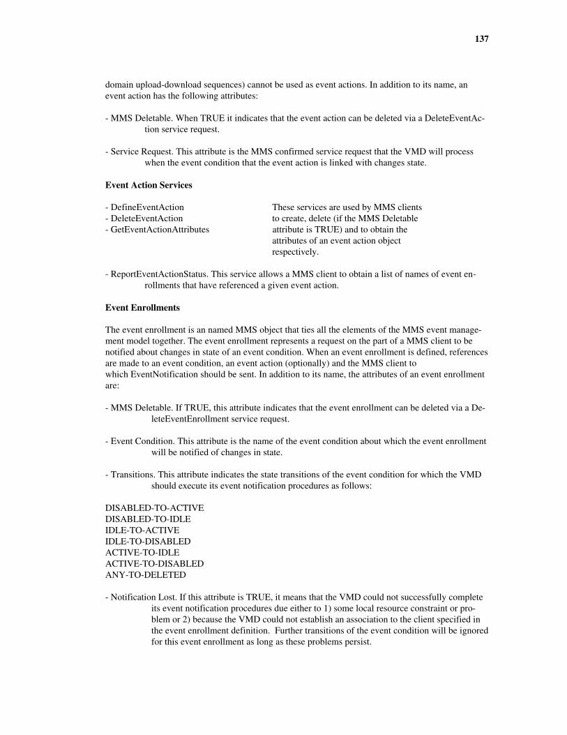
137
domain upload-download sequences) cannot be used as event actions. In addition to its name, anevent action has the following attributes:
- MMS Deletable. When TRUE it indicates that the event action can be deleted via a DeleteEventAc-tion service request.
- Service Request. This attribute is the MMS confirmed service request that the VMD will processwhen the event condition that the event action is linked with changes state.
Event Action Services
- DefineEventAction These services are used by MMS clients- DeleteEventAction to create, delete (if the MMS Deletable- GetEventActionAttributes attribute is TRUE) and to obtain the attributes of an event action object respectively.
- ReportEventActionStatus. This service allows a MMS client to obtain a list of names of event en-rollments that have referenced a given event action.
Event Enrollments
The event enrollment is an named MMS object that ties all the elements of the MMS event manage-ment model together. The event enrollment represents a request on the part of a MMS client to benotified about changes in state of an event condition. When an event enrollment is defined, referencesare made to an event condition, an event action (optionally) and the MMS client towhich EventNotification should be sent. In addition to its name, the attributes of an event enrollmentare:
- MMS Deletable. If TRUE, this attribute indicates that the event enrollment can be deleted via a De-leteEventEnrollment service request.
- Event Condition. This attribute is the name of the event condition about which the event enrollmentwill be notified of changes in state.
- Transitions. This attribute indicates the state transitions of the event condition for which the VMDshould execute its event notification procedures as follows:
DISABLED-TO-ACTIVEDISABLED-TO-IDLEIDLE-TO-ACTIVEIDLE-TO-DISABLEDACTIVE-TO-IDLEACTIVE-TO-DISABLEDANY-TO-DELETED
- Notification Lost. If this attribute is TRUE, it means that the VMD could not successfully completeits event notification procedures due either to 1) some local resource constraint or pro-blem or 2) because the VMD could not establish an association to the client specified inthe event enrollment definition. Further transitions of the event condition will be ignoredfor this event enrollment as long as these problems persist.
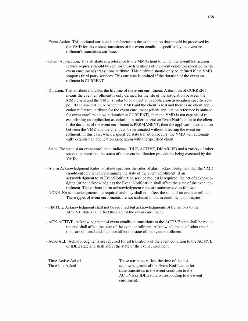
138
- Event Action. This optional attribute is a reference to the event action that should be processed bythe VMD for those state transitions of the event condition specified by the event en-rollment's transitions attribute.
- Client Application. This attribute is a reference to the MMS client to which the EventNotificationservice requests should be sent for those transitions of the event condition specified by theevent enrollment's transitions attribute. This attribute should only be defined if the VMDsupports third party services. This attribute is omitted if the duration of the event en-rollment is CURRENT.
- Duration. This attribute indicates the lifetime of the event enrollment. A duration of CURRENTmeans the event enrollment is only defined for the life of the association between theMMS client and the VMD (similar to an object with application association specific sco-pe). If the association between the VMD and the client is lost and there is no client appli-cation reference attribute for the event enrollment (client application reference is omittedfor event enrollments with duration = CURRENT), then the VMD is not capable of re-establishing an application association in order to send an EventNotification to the client.If the duration of the event enrollment is PERMANENT, then the application associationbetween the VMD and the client can be terminated without affecting the event en-rollment. In this case, when a specified state transition occurs, the VMD will automati-cally establish an application association with the specified client.
- State. The state of an event enrollment indicates IDLE, ACTIVE, DISABLED and a variety of otherstates that represent the status of the event notification procedures being executed by theVMD.
- Alarm Acknowledgment Rules. attribute specifies the rules of alarm acknowledgment that the VMDshould enforce when determining the state of the event enrollment. If anacknowledgment to an EventNotification service request is required, the act of acknowle-dging (or not acknowledging) the Event Notification shall affect the state of the event en-rollment. The various alarm acknowledgment rules are summarized as follows:
- NONE. No acknowledgments are required and they shall not affect the state of an event enrollment.These types of event enrollments are not included in alarm enrollment summaries.
- SIMPLE. Acknowledgment shall not be required but acknowledgments of transitions to theACTIVE state shall affect the state of the event enrollment.
- ACK-ACTIVE. Acknowledgment of event condition transitions to the ACTIVE state shall be requi-red and shall affect the state of the event enrollment. Acknowledgments of other transi-tions are optional and shall not affect the state of the event enrollment.
- ACK-ALL. Acknowledgments are required for all transitions of the event condition to the ACTIVEor IDLE state and shall affect the state of the event enrollment.
- Time Active Acked These attributes reflect the time of the last- Time Idle Acked acknowledgment of the Event Notification for
state transitions in the event condition to theACTIVE or IDLE state corresponding to the eventenrollment.
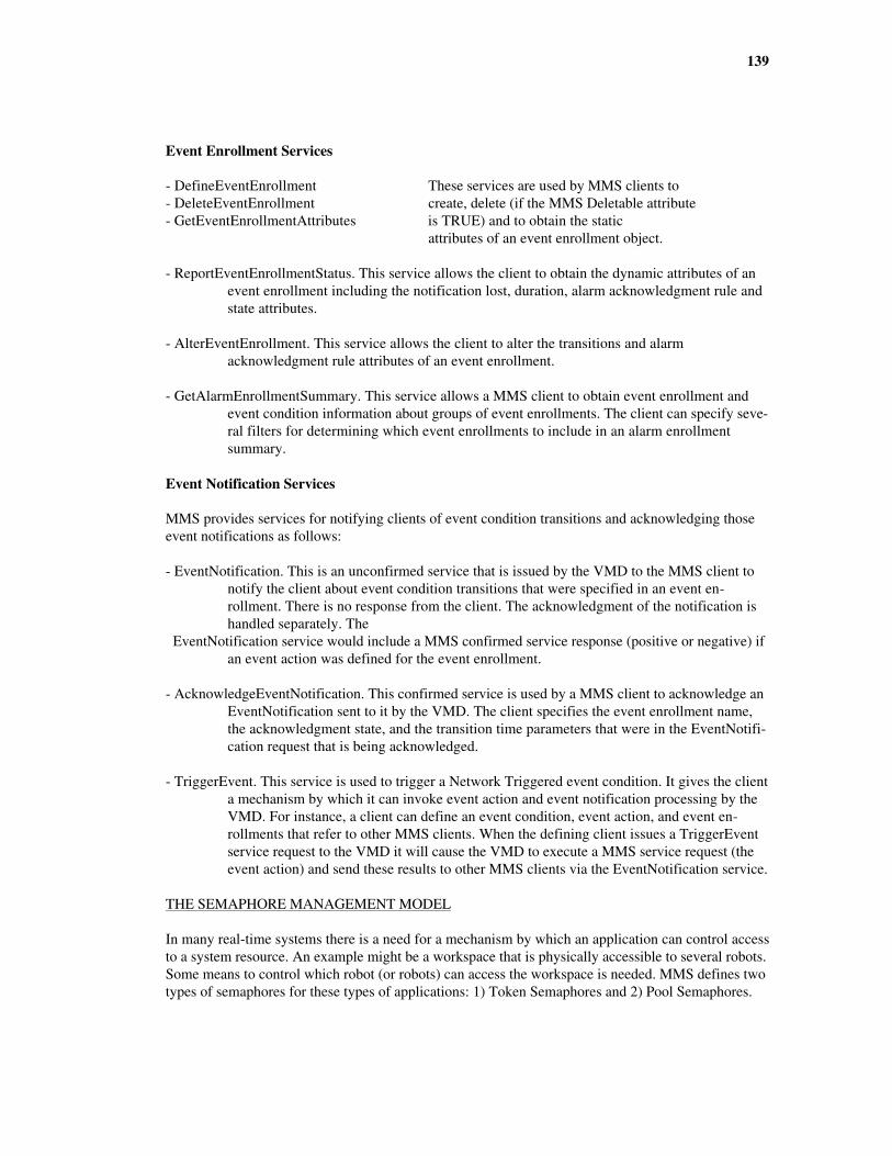
139
Event Enrollment Services
- DefineEventEnrollment These services are used by MMS clients to- DeleteEventEnrollment create, delete (if the MMS Deletable attribute- GetEventEnrollmentAttributes is TRUE) and to obtain the static attributes of an event enrollment object.
- ReportEventEnrollmentStatus. This service allows the client to obtain the dynamic attributes of anevent enrollment including the notification lost, duration, alarm acknowledgment rule andstate attributes.
- AlterEventEnrollment. This service allows the client to alter the transitions and alarmacknowledgment rule attributes of an event enrollment.
- GetAlarmEnrollmentSummary. This service allows a MMS client to obtain event enrollment andevent condition information about groups of event enrollments. The client can specify seve-ral filters for determining which event enrollments to include in an alarm enrollmentsummary.
Event Notification Services
MMS provides services for notifying clients of event condition transitions and acknowledging thoseevent notifications as follows:
- EventNotification. This is an unconfirmed service that is issued by the VMD to the MMS client tonotify the client about event condition transitions that were specified in an event en-rollment. There is no response from the client. The acknowledgment of the notification ishandled separately. The
EventNotification service would include a MMS confirmed service response (positive or negative) ifan event action was defined for the event enrollment.
- AcknowledgeEventNotification. This confirmed service is used by a MMS client to acknowledge anEventNotification sent to it by the VMD. The client specifies the event enrollment name,the acknowledgment state, and the transition time parameters that were in the EventNotifi-cation request that is being acknowledged.
- TriggerEvent. This service is used to trigger a Network Triggered event condition. It gives the clienta mechanism by which it can invoke event action and event notification processing by theVMD. For instance, a client can define an event condition, event action, and event en-rollments that refer to other MMS clients. When the defining client issues a TriggerEventservice request to the VMD it will cause the VMD to execute a MMS service request (theevent action) and send these results to other MMS clients via the EventNotification service.
THE SEMAPHORE MANAGEMENT MODEL
In many real-time systems there is a need for a mechanism by which an application can control accessto a system resource. An example might be a workspace that is physically accessible to several robots.Some means to control which robot (or robots) can access the workspace is needed. MMS defines twotypes of semaphores for these types of applications: 1) Token Semaphores and 2) Pool Semaphores.

140
Token Semaphores
A token semaphore is a named MMS object that can be a representation of some resource within thecontrol of the VMD to which access must be controlled. A token semaphore is modeled as a collectionof tokens that MMS clients take and relinquish control of using MMS services. This allows bothmultiple or exclusive ownership of the semaphore. When a MMS client owns the token, it providessome level of access to the underlying resource. An example might be where two users want to chan-ge a setpoint for the same control loop at the same time. These users could use a MMS token sema-phore containing only one token to represent the control loop in order to coordinate their accessto the setpoint. When the user "owns" the token, they can change the setpoint. The other would haveto wait until ownership is relinquished.
A token semaphore can also be used for the sole purpose of coordinating the activities of two MMSclients without representing any real resource. This kind of "virtual" token semaphore looks andbehaves the same except that they can be created and deleted by MMS clients using the DefineSema-phore service.
Because semaphores either represent a real resource or are used for the purpose of coordinating acti-vities between two or more MMS clients, the scope of a semaphore cannot be AA-Specific. Ifan object's scope is AA-Specific there can be only one client. Also, AA-Specific objects only exist aslong as the application association exists while real resources must exist outside the scope of any gi-ven application association. In addition to its name the token semaphore has the following attributes:
- Deletable. If TRUE it means that the semaphore does not represent any real resource within theVMD and can therefore be deleted by a MMS client via the DeleteSemaphore service.
- Number of Tokens. This attribute indicates the total number of tokens contained in the token sema-phore.
- Owned Tokens. This attribute indicates the number of tokens whose associated semaphore entrystate is OWNED.
- Hung Tokens. This attribute indicates the number of tokens whose associated semaphore entry stateis HUNG.
Pool Semaphores
A pool semaphore is similar to a token semaphore except that the individual tokens are identifiableand have a name associated with them. These named tokens can optionally be specified by the MMSclient when issuing TakeControl requests. The pool semaphore itself is a MMS object. The namedtokens contained in the pool semaphore are not MMS objects. They are representations of a real re-source in much the same way an unnamed variable object is. The name of the pool semaphore is sepa-rate from the names of the named tokens. Pool semaphores can only be used to represent some realresource within the VMD. Therefore, pool semaphores cannot be created or deleted using MMS ser-vice requests and cannot be AA-Specific in scope. In addition to the name of a pool semaphore thefollowing attributes also are defined by MMS:
- Free Named Tokens. The named tokens for which no associated semaphore entry exists.
- Owned Named Tokens. The named tokens for which the associated semaphore entry state isOWNED.
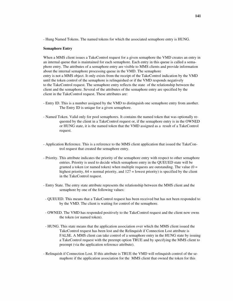
141
- Hung Named Tokens. The named tokens for which the associated semaphore entry is HUNG.
Semaphore Entry
When a MMS client issues a TakeControl request for a given semaphore the VMD creates an entry inan internal queue that is maintained for each semaphore. Each entry in this queue is called a sema-phore entry. The attributes of a semaphore entry are visible to MMS clients and provide informationabout the internal semaphore processing queue in the VMD. The semaphoreentry is not a MMS object. It only exists from the receipt of the TakeControl indication by the VMDuntil the token control of the semaphore is relinquished or if the VMD responds negativelyto the TakeControl request. The semaphore entry reflects the state of the relationship between theclient and the semaphore. Several of the attributes of the semaphore entry are specified by theclient in the TakeControl request. These attributes are:
- Entry ID. This is a number assigned by the VMD to distinguish one semaphore entry from another.The Entry ID is unique for a given semaphore.
- Named Token. Valid only for pool semaphores. It contains the named token that was optionally re-quested by the client in a TakeControl request or, if the semaphore entry is in the OWNEDor HUNG state, it is the named token that the VMD assigned as a result of a TakeControlrequest.
- Application Reference. This is a reference to the MMS client application that issued the TakeCon-trol request that created the semaphore entry.
- Priority. This attribute indicates the priority of the semaphore entry with respect to other semaphoreentries. Priority is used to decide which semaphore entry in the QUEUED state will begranted a token (or named token) when multiple requests are outstanding. The value (0 =highest priority, 64 = normal priority, and 127 = lowest priority) is specified by the clientin the TakeControl request.
- Entry State. The entry state attribute represents the relationship between the MMS client and thesemaphore by one of the following values:
- QUEUED. This means that a TakeControl request has been received but has not been responded toby the VMD. The client is waiting for control of the semaphore.
- OWNED. The VMD has responded positively to the TakeControl request and the client now ownsthe token (or named token).
- HUNG. This state means that the application association over which the MMS client issued theTakeControl request has been lost and the Relinquish if Connection Lost attribute isFALSE. A MMS client can take control of a semaphore entry in the HUNG state by issuinga TakeControl request with the preempt option TRUE and by specifying the MMS client topreempt (via the application reference attribute).
- Relinquish if Connection Lost. If this attribute is TRUE the VMD will relinquish control of the se-maphore if the application association for the MMS client that owned the token for this

142
semaphore entry is lost or aborted. If FALSE, the semaphore entry will enter the HUNGstate if the application association is lost or aborted.
- Control Timeout. This attribute is specified by the client in the TakeControl request and indicatesmany milliseconds the client should be allowed to control the semaphore once control isgranted. If the client has not relinquished control using a RelinquishControl request whenthe control timeout expires, the semaphore entry will be deleted and control of the sema-phore will be relinquished. If the control timeout attribute is omitted in the TakeControlrequest then no control timeout will apply for that semaphore entry.
- Abort on Timeout. This attribute is specified by the client in the TakeControl request and indicatesif the VMD should abort the application association with the owner client upon a controltimeout.
- Acceptable Delay. This attribute is specified by the client in the TakeControl request and indicateshow many milliseconds the client is willing to wait for control of the semaphore. If
control is not granted during this time, the VMD will respond negatively to the TakeControl re-quest. If the acceptable delay attribute is omitted from the TakeControl request then theclient is willing to wait indefinitely.
Semaphore Services
- TakeControl. Used by a client to request control of a semaphore.
- RelinquishControl. Used by a client to release control over a semaphore that the client currently hascontrol of.
- DefineSemaphore These services are used by clients to- DeleteSemaphore define and delete token semaphores that are used solely for coordinating the activities of two or more clients.
- ReportSemaphoreStatus These services are used to obtain the- ReportPoolSemaphoreStatus status (number of total, owned and hung tokens) of token and pool semaphores.
- ReportSemaphoreEntryStatus. This service is used by a client toobtain the attributes of semaphore entries corresponding to aspecified state.
OTHER MMS OBJECTS
Operator Stations
An operator station is a MMS object that can be used to represent character based input and outputdevices that may to attached to the VMD for the purpose of communicating with an operator local tothe VMD. MMS defines three types of operator stations:

143
- Entry. An entry only operator station consists of an input device only. This may be a keyboard orperhaps a bar code reader. The input data must be of the type Visible String consisting ofalpha-numeric characters only.
- Display. A display only operator station consists of a character based output display that can displayVisible String data (no graphics or control characters).
- Entry-Display. This type of operator stations consists of both a entry station and a display station.
Because the operator station is a representation of a physical feature of the VMD, it exists beyond thescope of any domain or application association. Therefore, MMS clients access the operatorstation by name without scope. MMS allows for any number of operator stations for a givenVMD. The services used by MMS clients to perform operator communications are:
- Input. MMS clients use this service to obtain a single input string from an input device. The servicehas an option for displaying a sequence of prompts on the display if the operator station isan entry-display type of operator station.
- Output. This service is used to display a sequence of output strings on the display of the operatorstation.
Journals
A MMS journal represents a log file that contains a collection of records (called journal entries) thatare organized by time stamps. Journals are used to store time based records of tagged variable data,user generated comments or combination of events and tagged variable data. Journal entries contain atime stamp that indicates when the data in the entry was produced (not when the journal entry wasmade). This allows MMS journals to be used for applications where a sample of a manufactured pro-duct is taken at one time, analyzed in a laboratory off-line, and then at a later time placed into thejournal. In this case the journal entry time stamp would indicate when the sample was taken.
MMS clients read the journal entries by specifying the name of the journal (which can be VMD-Specific or AA-Specific only) and either 1) the date/time range of entries that the client wishesto read or 2) by referring to the entry ID of a particular entry. The entry ID is a unique binary identi-fier assigned by the VMD to the journal entry when it is placed into the journal.
Each entry in a journal can be one of the following types:
- Annotation. This type of entry contains a textual comment. This is typically used to enter a com-ment regarding some event or condition that had occurred in the system.
- Data. This type of entry would contain a list of variable tags and the data associated with those tagsat the time indicated by the time stamp. Each variable tag is a 32-character name that doesnot necessarily refer to a MMS variable (although it might).
- Event-Data. This type of entry contains both variable tag data and event data. Each entry of this typewould include the same list of variable tags and associated data as described above alongwith a single event condition name and the state of that event condition at the time indica-ted by the time stamp.
The services available for MMS journals are as follows:

144
- ReadJournal. This service is used by a client to read one or more entries from a journal.
- WriteJournal. This service is used by a client to create new journal entries in a journal. A journalentry can also be created by local autonomous action by the VMD without a client using theWriteJournal service.
- CreateJournal These services are used by a client to- DeleteJournal create and delete (if the journal is deletable) journal objects. The CreateJournal service only creates the journal. It does not create any journal entries (see ReadJournal).
- InitializeJournal. This service is used by a client to delete all or some of the journal entries that are in a journal. For instance, a client can use InitializeJournal to delete old journal entries that are no longer of any interest.
Files
MMS also provides a set of simple file transfer services for devices that have a local file store but donot support a full set of file services via some other means. For instance, many robot implementationsof MMS use the file services for moving program (domain) files to the robot from a client application.The MMS file services support file transfer only, not file access. Although these file services are defi-ned in an annex within the MMS standard, they are widely supported by most commercial MMS im-plementations. The services for files are described below:
- FileOpen. This service is used by a client to tell the VMD to open a file and prepare it for a transfer.
- FileRead. This service is used to obtain a segment of the file's data from a VMD. The client wouldcontinue to issue FileOpen requests until the VMD indicates that all the data in the file hasbeen returned. The number of bytes returned in each FileRead response is determined sole-ly by the VMD (and can vary from one FileRead response to the next) and is not contro-llable by the client.
- FileClose. This service is used by a client to close a previously opened file. It is used after all thedata from the file has been read or can be used to discontinue a file transfer before it iscompleted.
- ObtainFile. This service is used by a client to tell the VMD to obtain a file. When a VMD receivesan ObtainFile request it would issue FileOpen, FileRead(s) and FileClose service requeststo the client application that issued the ObtainFile request. The client would then have tosupport the server functions of the FileOpen, FileRead, and FileClose services. A thirdparty option is available (if supported by the VMD) to tell the VMD to obtain the file fromanother node on the network using some protocol (which may or may not be MMS).
- FileRename These services are used to rename, delete,- FileDelete and obtain a directory of files on the- FileDirectory VMD respectively.
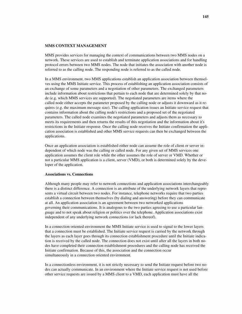
145
MMS CONTEXT MANAGEMENT
MMS provides services for managing the context of communications between two MMS nodes on anetwork. These services are used to establish and terminate application associations and for handlingprotocol errors between two MMS nodes. The node that initiates the association with another node isreferred to as the calling node. The responding node is referred to as the called node.
In a MMS environment, two MMS applications establish an application association between themsel-ves using the MMS Initiate service. This process of establishing an application association consists ofan exchange of some parameters and a negotiation of other parameters. The exchanged parametersinclude information about restrictions that pertain to each node that are determined solely by that no-de (e.g. which MMS services are supported). The negotiated parameters are items where thecalled node either accepts the parameter proposed by the calling node or adjusts it downward as it re-quires (e.g. the maximum message size). The calling application issues an Initiate service request thatcontains information about the calling node's restrictions and a proposed set of the negotiatedparameters. The called node examines the negotiated parameters and adjusts them as necessary tomeets its requirements and then returns the results of this negotiation and the information about it'srestrictions in the Initiate response. Once the calling node receives the Initiate confirmation the appli-cation association is established and other MMS service requests can then be exchanged between theapplications.
Once an application association is established either node can assume the role of client or server in-dependent of which node was the calling or called node. For any given set of MMS services oneapplication assumes the client role while the other assumes the role of server or VMD. Whether ornot a particular MMS application is a client, server (VMD), or both is determined solely by the deve-loper of the application.
Associations vs. Connections
Although many people may refer to network connections and application associations interchangeablythere is a distinct difference. A connection is an attribute of the underlying network layers that repre-sents a virtual circuit between two nodes. For instance, telephone networks require that two partiesestablish a connection between themselves (by dialing and answering) before they can communicateat all. An application association is an agreement between two networked applicationsgoverning their communications. It is analogous to the two parties agreeing to use a particular lan-guage and to not speak about religion or politics over the telephone. Application associations existindependent of any underlying network connections (or lack thereof).
In a connection oriented environment the MMS Initiate service is used to signal to the lower layersthat a connection must be established. The Initiate service request is carried by the network throughthe layers as each layer goes through its connection establishment procedure until the Initiate indica-tion is received by the called node. The connection does not exist until after all the layers in both no-des have completed their connection establishment procedures and the calling node has received theInitiate confirmation. Because of this, the association and the connection occursimultaneously in a connection oriented environment.
In a connectionless environment, it is not strictly necessary to send the Initiate request before two no-des can actually communicate. In an environment where the Initiate service request is not used beforeother service requests are issued by a MMS client to a VMD, each application must have all the
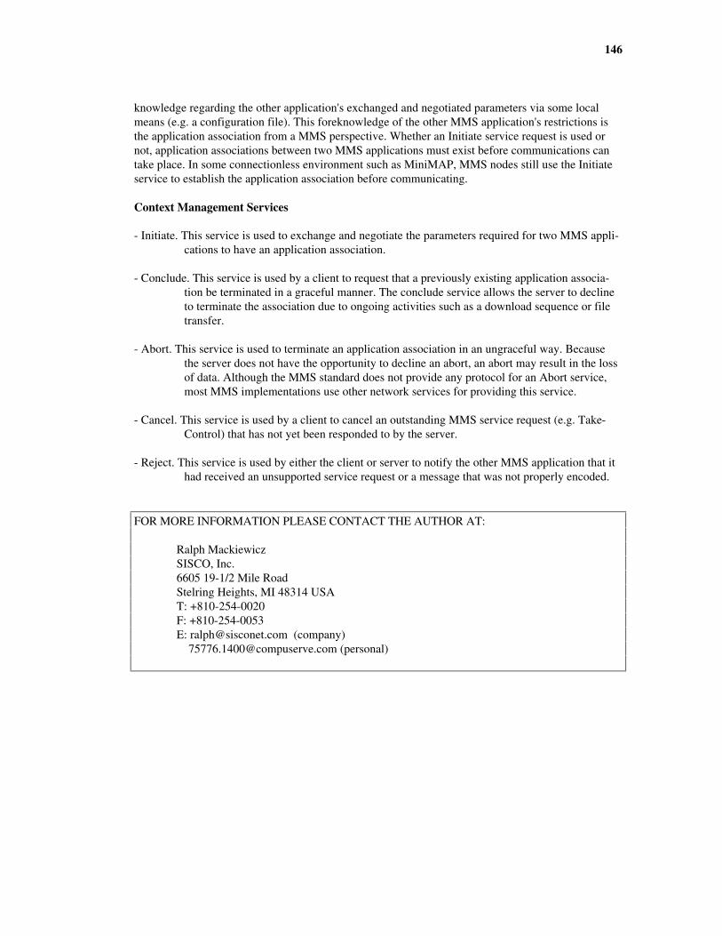
146
knowledge regarding the other application's exchanged and negotiated parameters via some localmeans (e.g. a configuration file). This foreknowledge of the other MMS application's restrictions isthe application association from a MMS perspective. Whether an Initiate service request is used ornot, application associations between two MMS applications must exist before communications cantake place. In some connectionless environment such as MiniMAP, MMS nodes still use the Initiateservice to establish the application association before communicating.
Context Management Services
- Initiate. This service is used to exchange and negotiate the parameters required for two MMS appli-cations to have an application association.
- Conclude. This service is used by a client to request that a previously existing application associa-tion be terminated in a graceful manner. The conclude service allows the server to declineto terminate the association due to ongoing activities such as a download sequence or filetransfer.
- Abort. This service is used to terminate an application association in an ungraceful way. Becausethe server does not have the opportunity to decline an abort, an abort may result in the lossof data. Although the MMS standard does not provide any protocol for an Abort service,most MMS implementations use other network services for providing this service.
- Cancel. This service is used by a client to cancel an outstanding MMS service request (e.g. Take-Control) that has not yet been responded to by the server.
- Reject. This service is used by either the client or server to notify the other MMS application that ithad received an unsupported service request or a message that was not properly encoded.
FOR MORE INFORMATION PLEASE CONTACT THE AUTHOR AT:
Ralph MackiewiczSISCO, Inc.6605 19-1/2 Mile RoadStelring Heights, MI 48314 USAT: +810-254-0020F: +810-254-0053E: [email protected] (company) [email protected] (personal)

ANEXO C.
Resumen de los Comandos Aceptados por las Máquinas E. C. S. del Centro Co-
lombo-Italiano Americo Vespucci en el SENA
Códigos GG00 Desplazamiento en marcha rápidaG01 Interpolación lineal, dim. medioG02 Interpolación circular, sentido horarioG03 Interpolación circular, sentido antihorarioG04 Parada temporizadaG05 Parada suspensiva
G08/09 Aceleración/desaceleraciónG10 Interpolación lineal, dimensión grandeG11 Interpolación lineal, dimensión pequeña
G13-15 Elección de ejesG17-19 Elección de planos
G20 Rotación AutomáticaG22 Posicionamiento con desaceleración y paradoG33 Roscado constanteG38 Cambio de herramienta, auto inclusoG39 Cambio de herramienta, auto exclusoG40 Anulación de la corrección de herramienta
G41-44 Modo interpolación motociclista, corrección de la herramientaG61 Macro de repetición de partes de programaciónG62 Macro para repetición de ciclos fijosG63 Macro de roscadoG64 Macro de desbaste cuadriláteroG66 Macro de desbaste generalizadoG72 Posicionamiento en rápidoG74 Posicionamiento en maquinado
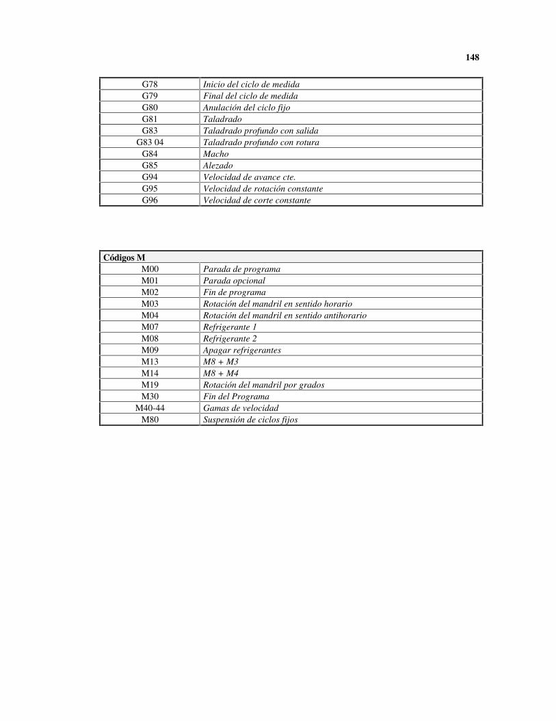
148
G78 Inicio del ciclo de medidaG79 Final del ciclo de medidaG80 Anulación del ciclo fijoG81 TaladradoG83 Taladrado profundo con salida
G83 04 Taladrado profundo con roturaG84 MachoG85 AlezadoG94 Velocidad de avance cte.G95 Velocidad de rotación constanteG96 Velocidad de corte constante
Códigos MM00 Parada de programaM01 Parada opcionalM02 Fin de programaM03 Rotación del mandril en sentido horarioM04 Rotación del mandril en sentido antihorarioM07 Refrigerante 1M08 Refrigerante 2M09 Apagar refrigerantesM13 M8 + M3M14 M8 + M4M19 Rotación del mandril por gradosM30 Fin del Programa
M40-44 Gamas de velocidadM80 Suspensión de ciclos fijos