TO - Searsdownload.sears.com/misc/spin_prod_731195612.pdf · el horno de empotre puede estar de...
8
INSTALLATION AND SERVICE MUST BE PERFORMED BY A QUALIFIED INSTALLER. IMPORTANT: SAVE FOR LOCAL ELECTRICAL INSPECTOR'S USE. READ AND SAVE THESE INSTRUCTIONS FOR FUTURE REFERENCE. FORYOUR SAFETY: Do not store or use gasoline or other flammable vapors and liquids in the vicinity of this or any other appliance. GENERAL INFORMATION The Warm & Serve Drawer can be used: o As a stand alone appliance • As a combination Warm & Serve Drawer with a 30" (76 cm) built-in oven mounted above IMPORTANT: The warmer drawer must be installed on a leveled surface from left to right, rear to front and the surface must be capable of supporting 1O0 Ibs (45 Kg). Warm & Serve Drawer Dimensions NOTE: A 60" (1 52 cm) long cable is supplied with the Warm & Serve Drawer. Stand Alone Installation 10" (25.4cm) 30" (76,2cm) 23 3/8" (59,4 cm) Min. 8 3/8" (21,3cm) 28 1/2 " (72,4 cm) Max. 8 5/8" (21,9cm) 28 3/4 " (73 cm) 24"(61cm) IMPORTANT: The Warm & Serve Drawer runs off a single phase three-wire 120 volt, 60 hertz, AC only electrical supply with ground. Combination Warm & Serve Drawer/ 30" (76 cm) Built-in Oven Installation Caution: Two 3" (7,6 cm) wide X 3/4" (1,9 cm) thick planks have to be install and they should be able to support 200 pounds• (90,7 Kg) B\ C N*-101/8 (25.7cm) Min. is a Critical dimension and has to he respected. J** =3 (7.6cm) Max. Electrical Junction Box for wall oven can he lower than warmer drawer cutout or higher than walloven cutout. 10"(25.4cm) 30"(76,2cm) 233/8"(59,4cm) ........... TO Min.8 3/8"(21,3cm) 281/2" (72,4cm) 24"(61cm) 1 1/2"(3,8cm) Bependsoncritical Max. 8 5/8"(21,9cm) 283/4" (73crn) dimensionH Printed in the USA P/N 318201805 (0606) Rev. C English pages 1-2; Espaflol p_iginas 3-4 Fran_ais pages 5%; Notes - pages 7-8
Transcript of TO - Searsdownload.sears.com/misc/spin_prod_731195612.pdf · el horno de empotre puede estar de...

INSTALLATION AND SERVICE MUST BE PERFORMED BY A QUALIFIED INSTALLER.IMPORTANT: SAVE FOR LOCAL ELECTRICAL INSPECTOR'S USE.
READ AND SAVE THESE INSTRUCTIONS FOR FUTURE REFERENCE.FORYOUR SAFETY: Do not store or use gasoline or other flammable vapors and liquids in the
vicinity of this or any other appliance.
GENERAL INFORMATIONThe Warm & Serve Drawer can be used:
o As a stand alone appliance• As a combination Warm & Serve Drawer with a 30" (76 cm) built-in oven mounted above
IMPORTANT: The warmer drawer must be installed on a leveled surface from left to right, rear to front and the surfacemust be capable of supporting 1O0 Ibs (45 Kg).
Warm & Serve Drawer Dimensions
NOTE: A 60" (152 cm) long cable is supplied with theWarm & Serve Drawer.
Stand Alone Installation
10" (25.4cm) 30" (76,2cm) 23 3/8" (59,4cm)
Min. 8 3/8" (21,3cm) 28 1/2 " (72,4cm)
Max. 8 5/8" (21,9cm) 28 3/4" (73 cm)
24"(61cm)
IMPORTANT: The Warm & Serve Drawer runs off a
single phase three-wire 120 volt, 60 hertz, AC onlyelectrical supply with ground.
Combination Warm & Serve Drawer/30" (76 cm) Built-in Oven Installation
Caution: Two 3" (7,6 cm) wide X3/4" (1,9 cm) thick planks have tobe install and they should be ableto support 200 pounds• (90,7 Kg)
B\ C
N*-101/8 (25.7cm) Min. is a Criticaldimension and has to he respected.
J** =3 (7.6cm) Max. Electrical Junction Box for wall oven can helower than warmer drawer cutout or higher than walloven cutout.
10"(25.4cm) 30"(76,2cm) 233/8"(59,4cm)
........... TO
Min.8 3/8"(21,3cm) 281/2" (72,4cm) 24"(61cm) 1 1/2"(3,8cm)Bependsoncritical
Max.8 5/8"(21,9cm) 283/4" (73crn) dimensionH
Printed in the USA
P/N 318201805 (0606) Rev. C
English pages 1-2; Espaflol p_iginas 3-4Fran_ais pages 5%; Notes - pages 7-8
Important Notes to the InstallerI. Read all instructions contained in these installation
instructions before installing appliance.2. Remove all packing material from appliance before
connecting the electrical supply.3. Observe all governing codes and ordinances.4. Be sure to leave these instructions with the consumer.
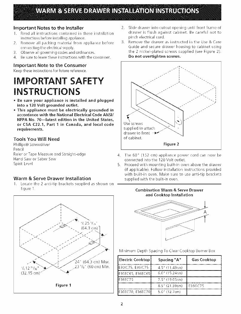
2. Slide drawer into cutout opening until front frame ofdrawer is flush against cabinet. Be careful not topinch electrical cord.
3. Remove the drawer as instructed in the Use & CareGuide and secure drawer housing to cabinet usingthe 2 nickel-plated screws supplied (see Figure 2).Do not overtighten screws.
Important Note to the ConsumerKeep these instructions for future reference.
IMPORTANT SAFETYINSTRUCTIONS• Be sure your appliance is installed and plugged
into a 120 Volt grounded outlet.
• This appliance must be electrically grounded inaccordance with the National Electrical Code ANSI/
NFPA No, 70--latest edition in the United States,
or CSA C22,1, Part 1 in Canada, and local code
requirements.
Tools You Will Need
Phillips@ ScrewdriverPencil
Ruler or Tape Measure and Straight-edgeHand Saw or Saber Saw
Spirit Level
Warm & Serve Drawer Installation
I. Locate the 2 anti-tip brackets supplied as shown onfigure I.
Use screwssupplied to attachdrawer to front -_"of cabinet,
Figure 2
.
5.
The 60" (152 cm) appliance power cord can now beconnected into the 120 Volt outlet.Proceed with mounting built-in oven above the drawer(if applicable). Follow installation instructions providedwith built-in oven. Make sure to use anti-tip bracketssupplied with the built-in oven.
Combination Warm & Serve Drawer
and Cooktop installation
Figure 1
A
Minimum Depth Spacing To Clear Cooktop Burner Box
Electric Cooktop Spacing "A" Gas Cooktop
E301C75, E361C75 4.5" (11.43cm)
E30EC65, E36EC65 6.0" (15.24cm)
E36EC75 7.5" (19.05cm)
8.5" (21.59cm) E36GC75
E30EC70, E36EC70 5.0" (12.7cm)
LA INSTALACION Y EL SERVICIO DEBEN SER EJECUTADOS POR UN INSTALADOR CALIFICADO.
IMPORTANTE: GUARDE ESTAS INSTRUCCIONES PARA EL USO DEL INSPECTOR LOCAL DEELECTRICIDAD. LEA Y GUARDE ESTAS INSTRUCCIONES PARA FUTURAS REFERENCIAS.
F.'_ PARA SU SEGURIDAD: No almacene o use gasolina u otros vapores y Jiquidos combustibJescerca a _ste o a cualquier otro eJectrodom_stico.
INFORMACION GENERALElcajOn calentador puede ser usado:* Como unidad independiente
Enuna combinaci6n entre el caj6n calentador y el homo de 30 (76 cm) pulgadas integrado y montado por encima del caj6n
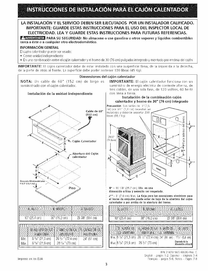
IMPORTANTE: El caj6n calentador debe de estar instalado con una surperficie liana, de la izquierda a la dececha,
de la parte de atr_is al frente. La superficie debe poder sostener 100 libras (45 Kg).
Dimensiones del caj6n calentador
NOTA: Un cable de 60" (152 cm) de largo es
suministrado con el cajOn calentador.
Instalaci6n de la unidad independiente
10"(25.4cm) 30" (76,2cm) 233/8"(59,4cm)
8 3/8"(21,3cm) 281/2"(72,4cm) 24" (61cm)8 5/8"(21,9cm) 283/4" (73cm)
IMPORTANTE: El cajOn calentador funciona con un
suministro de energia electrica de corriente alterna, detres cables, de una sola fase, de 120 voltios, 60 hertzcon linea a tierra.
Instalaci6n de la combinaci6n caj6n
calentador y homo de 30" (76 cm) integrado
Precauci6n: Dos tablas de 3"(7,6cm) pot 3/4" (1,9 cm) necesitan serinsta[adas y deberan soportar 200libras (90,7 Kg)
B\
H* : 10 1/8" (25.7 cm) Min. es unadilnensi6n cr{tica y necesita set respetada.
J**= 3" (7.6 cm) Max. La Caja para las conexiones electricas parael horno de empotre puede estar de bajo de la abertura del cajoncalentador 0 p0r arriba de la abertura del homo.
10" (25.4cm) 30"(76,2cm) 233/8"(59,4crn)
Min._ 3/8"(21,3cm) 281/_,,(72,4cm) 241'(61cm) 11/2"(3,8cm)
Max.B5/8"(21,9cm) 283/4"(73cm) Uependedeladimensi6n¢riticaH
Impreso en los EUA
P/N 318201805 (0606) Rev.English - pages 1-2; Espatiol - paginas 3-4
Fran_ais - pages 5-6; Notes - Pages 7-8

Notas importantes para el instaladorI. Leatodas las instrucciones de instalaci6n antes de instalar
el electrodom6stico.2. Retiretodos losmaterialesde empaquedelelectrodom6stico
antes de conectar la fuente de energia.3. Observe todos los cOdigos y leyesdel gobierno4. Aseg0rese de dejarle estas instrucciones al consumidor.
2. Deslice el caj6n hacia dentro de la abertura de laaberturahasta que el marco frontal del cajOn este a ras contra elgabinete. Tenga cuidado de no )inchar el cable el_ctrico.
3. Remover el cajOncomo indica el manual de uso y cuidadoasegureel marco contra el gabinete utilizando los tornillosniquelados. (vea la Figura 2). No apriete demasiado lostornillos.
Nota importante para el consumidorGuarde estas instrucciones para futura referencia.
INSTRUCCIONESIMPORTANTES DE
SEGURIDADAseg_rese de que su electrodom_stico est_ instaladoy conectado en un tomacorriente de 120 voltios contierra.
Este electrodom_stico debe ser puesto el_ctricarnentea tierra de acuerdo con el C6digo Nacional El_ctricoANSI/NFPA No 7--de la _ltima edici6n de los Estados
Unidos, o la CSA C22,1, Parte 1 en Canada, y con losrequisitos de c6digos locales.
Herramientas que usted necesitaDestornillador de estrella (Phillips)LapizRegla o cinta medidora y regla rectaSerrucho manual o serrucho de sableNivel de burbuja
//
1
Utilizar los tornillos
para fijar el caj6n ....al frente del-----_"
gabinete.
Figura 2
4. El cable de 60" (152 cm) del electrodom_stico puedeahora conectarse en un tomacorriente de 120 voltios contierra.
5. Proceda con el montaje del homo integrado por encimadel caj6n (si esel caso). Siga lasinstrucciones provistas conel homo integrado. Aseg0rese de usar las abrazaderasantideslizantes provistas con el homo integrado.
Instalad6n del cajon calentadorI. Instalor los 2 brackets anti-volteo corno muestro la figura I.
Combinaci6n del caj6n calentador yla instalaci6n de una cubierta
Figura 1
A
Profundidad minima para no interferir con la caja dequemadores.
Cubierta El_ctrica
E301C75, E361C75
E30EC65, E36EC65
E36EC75
Distancia "A" Cubierta a Gas
4.5" (I 1.43cm)
6.0" (15.24cm)
7.5" (19.05cm)
8.5" (21.59cm) E36GC75
E30EC70, E36EC70 5.0" (12.7cm)

L'INSTALLATION ET L'ENTRETIEN DOIVENT ETRE EFFECTU[:S PAR UN INSTALLATEUR COMP[:TENT,IMPORTANT : CONSERVEZ CES INSTRUCTIONS POUR L'INSPECTEUR D'I_LECTRICITI_ LOCAL. LISEZ
ET CONSERVEZ CES INSTRUCTIONS POUR RleFERENCES ULTERIEURES.
POUR VOTRE SECURITE: N'entreposez et n'utilisez pas d'essence ou autres gaz etliquides inflammables a proximit_ de cet appareil ou de tout autre appareil m_nager.
RENSEIGNEMENTSGENERAUX
Ce tiroir-r_chaud peut &tre utilis_ cornme:* Appareil autonome* Tiroir-r@chaud combin@a un four encastr@de 30" (76 cm) superpos@
IMPORTANT: Le tiroir-rechaud doit _tre install@sur une surface de niveau, de gauche a droite et de I'arri@rea I'avant. Lasurface doit pouvoir supporter 100 Ibs(45 Kg).
Dimensions du tiroir-r_chaud
NOTE: Un c_ble de 60" (152 cm) est fourni avec le tiroir-r@chaud.
Installation pour appareil autonome
plancher 41/2" (11,4 cm)
10" (25.4cm) 30" (76,2cm) 233/8"(59,4cm)
8 3/s"(21,3cm) 28V2" (72,4cm) 24" (61cm)8%" (21,9cm) 283/4"(73cm)
IMPORTANT: Le tiroir-r_chaud fonctionne seulement
avec un circuit electrique mis a la terre a 3 fils de 120
volts, monophas_, 60 Hz CA.
Combin_ tiroir-r_chaud/
four encastr& de 30" (76 cm)
Attention: Deux planches de 3" (7,6cm) de large X 3/4" (1,9 cm) d'epaisdoivent _tre installees et olios doivent_tre en mesure de supporter un poi(de 200 Ibs. (90,7 Kg)
B\ C
H* =10 1/8" (25.7 crn) Min. est unedimension critique et deft Otre respect_e.
J**= 3" (7.6 cr'n) Max. La buite de junction _lectrJque pour Je fourencastr_ peut _tre situ_e en has du d_c0upage pour le tireirchaufant ou en haut du d_cuupage poor le four encastr_.
10"(25.4cm) 30" (76,2cm) 233/8"(59,4cm)
iVlin.8 s/8"(21,3cm) 28V2"(72,4cm) 24"(61cm) 1 _/2"(3,8cm)
Max8 s/s"(21,9cm) 28%" (73cm) _,.,_d_ladime,.sio_ critique El
Imprime aux Etats-Unis
P/N 318201805 (0606) Rev, C
English - pages 1-2; Espa_ol - paginas 3-4FranCais- pages 5-6; Notes - pages 7-8

Notes importantes a IqnstallateurI. Liseztoutes les instructions d'installation avant de proc6der
I'installation de cet appareil.2. Retirez tout le materiel d'emballage de I'appareil avant de
brancher I'alimentation _lectrique.3. Observez tousles r6glements et codes Iocaux applicables.4. Assurez-vous de laisser ces instructions a I'utilisateur.
2. Glissez le tiroir dans I'ouverture du d6coupage jusqu'a ceque son cadre avant soit tout contre I'armoire. Veillez a nepas coincer le cordon _lectrique.
3. Retirez le tiroir tel qu'expliqu_ dans le manuel d'utilisationet d'entretien et fixez le chassisdu tiroir a I'armoire a I'aide
des 2 vis plaqu6es au nickel fournies. Ne serrez pas lesvis outre mesure. (voir figure 2)
Note importante _ I'utilisateurConservez ces instructions pour r_f_rences ulterieures.
INSTRUCTIONS DESI CURITI[: IMPORTANTES• Assurez-vous que votre appareil est install_ et
raccord_ a une prise murale de 120 volts raise a laterre.
• Cet appareil doit _tre mis _ la terre conform_ment aucode d'_lectrkit_ national ANSUNFPA No. 70, derniere_dition, aux Etats-Unis, ou a I'ACNOR C22.1, partie 1au Canada, et aux codes et reglements Jocaux.
OutilS n_cessaires
Tournevis PhillipsCrayonR_gle ou ruban a mesurer et _querreScie a main ou scie sauteuseNiveau a bulle
Installation d'un tiroir=r_chaud
1. Localisez les supports anti-bascules tel qu'indiqu_ a la fig-ure 1.
% 25 5/16"(64.3 cm):
(64.3 cm) Max.23 5/8" (60 cm) Min.
Figure 1
Utilisez les visfournies pour fixer le ..chassis du tiroir--_ _"
I'armoire.
Figure 2
4. Le cordon d'alimentation de I'appareil de 60" (152 cm)peut a present _tre branch_ a la prise murale de 120 volts.
5. Procedez maintenant au montage du four encastr_superpose au tiroir-r_chaud (s'il y a lieu). Suivez lesinstructions d'installation fournies avec le four encastr_.Assurez-vousd'utiliser lescrochets anti-basculesfournis avecle four.
installation combin_tiroir-r_chaud / table de cuisson
A
Espacement minimum pour ne pas entrer en interferenceavec le bottler de la table de cuisson.
Table de Table de cuisson
cuisson _lectrique Espacement "A" au gaz
E301C75, E361C75 4.5" (11.43cm)
E30EC65, E36EC65 6.0" (15.24cm)
E36EC75 7.5" (19.05cm)
8.5" (21.59cm) E36GC75
E30EC70, E36EC70 5.0" (12.7cm)

Notes - Notas

Notes _ Notas