


Idiomas
Páginas
Jurídico


HIMOINSA empresa con certificación de calidad ISO 9001:2008Los grupos electrógenos HIMOINSA cumplen con las siguientes directivas:
• 2006/42/CE Seguridad de Máquinas.• 2004/108/CE de Compatibilidad Electromagnética.• EN 12100, EN 13857 y EN 60204 de Diseño y Fabricación.• EPA 40 CFR Parte 89 sobre emisión de gases.• 2000/14/CE de Emisiones Sonoras en el Entorno de Máquinas de uso al aire libre.• 2006/95/CE de Baja Tensión.
HIMOINSA company with quality certification ISO 9001:2008HIMOINSA gensets are compliant with the following directives.
• 2006/42/CE Machinery safety.• 2004/108/CE Electromagnetic compatibility.• EN 12100, EN 13857 y EN 60204 Design and manufacturing.• Exhaust emission EPA 40 CFR Part 89• 2000/14/CE Sound Power level. Noise emissions outdoor equipment.• 2006/95/CE Low voltage.
Ambient conditions of reference: 1000 mbar, 25ºC, 30% relative humidity. Power according to ISO 3046 normative.
P.R.P. Prime Power - ISO 8528 : prime power is the maximum power available during a variable power sequence, which may be run for an unlimited number of hours per year, between stated maintenance intervals. The permissible average power output during a 24 hours period shall not exceed 80% of the prime power. 10% overload available for governing purposes only.
Standby Power (ISO 3046 Fuel Stop power): power available for use at variable loads for limited annual time (500h), within the following limits of maximum operating time: 100% load 25h per year – 90% load 200h per year. No overload available. Applicable in case of failure of the main in areas of reliable electrical network.
Himoinsa reserves the right to modify any characteristic prior notifice. The illustrations may include optional equipment and/or accessories. Not contractual images. The technical indications described in this brochure correspond to the information available at the moment of printing. ©HIMOINSA
Condiciones ambientales de referencia: 1000 mbar, 25ºC, 30% humedad relativa. Potencia según la norma ISO 3046.
P.R.P. - ISO 8528: es la potencia máxima disponible para un ciclo de potencia variable que puede ocurrir por un número ilimitado de horas por año, entre los periodos de mantenimiento señalados. La potencia media consumible durante un periodo de 24 horas no debe rebasar del 80% de la P.R.P. 10 % de sobrecarga es permitido solo para efectos de regulación.
Stand-byPower (ISO 3046 Fuel Stop power) - Es la potencia máxima disponible para empleo bajo cargas variables por número limitado de horas por año (500h) dentro de los siguientes límites máximos de funcionamiento: 100% de la carga 25h/año - 90% de la carga 200h/año. No existe sobrecarga. Es aplicable en caso de interrupción de la distribución en zonas de red eléctrica fiable.
Himoinsa se reserva el derecho de modificar cualquier característica sin previa notificación. Las ilustraciones pueden incluir equipamiento opcional y/o accesorios. Imágenes no contractuales. Las indicaciones técnicas descritas en este catálogo se corresponden con la información disponible en el momento de la impresión. ©HIMOINSA
HIM
OIN
SA®
Pro
duct
Ran
ge |
Pub
licat
ion
02-
2012
2
ASIA - PACÍFICO / PACIFIC - ASIA
HIMOINSA CHINA CO. LTDTLF. +86 519 86 22 66 88 FAX: +86 519 86 22 66 87
HIMOINSA FAR EAST PTE LTDTLF. +65 6 265 10 11 FAX: +65 6 265 11 41
HIMOINSA CENTRAL ASIA (KAZAKHSTAN)TLF/FAX: +7 727 392 3688
ORIENTE MEDIO / MIDDLE EAST
HIMOINSA MIDDLE EAST FZETLF. +971 4 887 33 15 FAX: +971 4 887 33 18
AMERICA
HIMOINSA MEXICOTLF. +52 (33) 3675 86 46 FAX: +52 (33) 3914 25 90
HIMOINSA POWER SYSTEMS, INC. (USA)TLF. +1 913 495 55 57 FAX: +1 913 495 55 75
HIMOINSA PTY (PANAMA)TLF. +507 232 57 41 FAX: +507 232 64 59
HIMOINSA LATINOAMERICA (Rep. Argentina)TLF. +54 2320 40 1900 / 1901
EUROPA / EUROPE
GENELEC S.A.S. (HIMOINSA FRANCE)TLF. +33 474 62 65 05 FAX: +33 474 09 07 28
HIMOINSA ITALIA S.R.L.TLF. +39 0444 58 09 22 FAX: +39 0444 186 74 31
HIMOINSA PORTUGAL LDATLF. +351 21 426 65 50 FAX: +351 21 426 65 69
HIMOINSA POLSKA SP. Z O. O.TLF. +48 22 868 19 18 FAX: +48 22 868 19 31
HIMOINSA DEUTSCHLANDTLF. +49 9372 9495447 FAX: +49 6009 62108
HIMOINSA CENTRO (Madrid)
TLF. +34 91 684 21 06 FAX +34 91 684 21 07
Centro de Distribución RecambiosSpare Parts Distribution Centre
TLF. +34 968 33 40 15 FAX +34 968 19 11 53
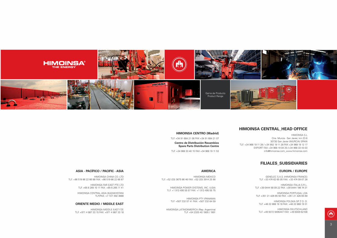
HIMOINSA CENTRAL_HEAD OFFICEHIMOINSA S.L
Ctra. Murcia - San Javier, km 23.630730 San Javier (MURCIA) SPAIN
TLF. +34 968 19 11 28 / +34 902 19 11 28 FAX +34 968 19 12 17EXPORT FAX +34 968 19 04 20 /+34 968 33 43 03
[email protected]_www.himoinsa.com
FILIALES_SUBSIDIARIES
Gama de ProductoProduct Range
3
I ÍNDICE_INDEX
PG. 56
PG. 58
PG. 52
PG. 71
PG. 73
PG. 74
PG. 75
PG. 32
PG. 66
PG. 38
PG. 66
PG. 28
HLA
HZA
AIRE | AIR
AGUA | WATER
HDW
HRVW
HRDW
HRMW
HRTW
HYW
HFW
HRYW
HSW
HRFW
HVW
HMW
HRSW
PG. 44
PG. 48
PG. 68
PG. 63
PG. 65
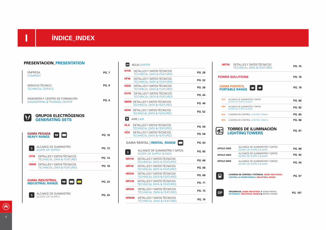
GAMA PORTATILPORTABLE RANGE
PG. 87
PG. 88
TORRES DE ILUMINACIÓNLIGHTING TOWERS
APOLO 4000 PG. 92
PG. 94
HZA
HLA PG. 80
PG. 82
HLA PG. 85
PRESENTACION_PRESENTATION
EMPRESACOMPANY
SERVICIO TÉCNICOTECHNICAL SERVICE
PG. 7
PG. 8
PG. 12
PG. 14HTW
HMW PG. 18
ALCANCE DE SUMINISTROSCOPE OF SUPPLY
ALCANCE DE SUMINISTROSCOPE OF SUPPLY
PG. 24
INGENIERÍA Y CENTRO DE FORMACIÓNENGINEERING & TRAINING CENTER PG. 9
GRUPOS ELECTRÓGENOSGENERATING SETS
SS
GAMA PESADAHEAVY RANGE PG. 10
S
PG. 23GAMA INDUSTRIALINDUSTRIAL RANGE
GAMA RENTAL | RENTAL_RANGE
PG. 76POWER SOLUTIONS
PG. 79
APOLO 2000
APOLO 8000
CUADROS DE CONTROL Y POTENCIA_GAMA INDUSTRIALCONTROL & POWER PANELS_INDUSTRIAL RANGE
OP OPCIONALES_GAMA INDUSTRIAL Y GAMA RENTALOPTIONALS_INDUSTRIAL RANGE & RENTAL RANGE
PG. 97
PG. 107
HZA PG. 86
DETALLES Y DATOS TÉCNICOSTECHNICAL DATA & FEATURES
DETALLES Y DATOS TÉCNICOSTECHNICAL DATA & FEATURES
DETALLES Y DATOS TÉCNICOSTECHNICAL DATA & FEATURES
DETALLES Y DATOS TÉCNICOSTECHNICAL DATA & FEATURES
DETALLES Y DATOS TÉCNICOSTECHNICAL DATA & FEATURES
DETALLES Y DATOS TÉCNICOSTECHNICAL DATA & FEATURES
DETALLES Y DATOS TÉCNICOSTECHNICAL DATA & FEATURES
DETALLES Y DATOS TÉCNICOSTECHNICAL DATA & FEATURES
DETALLES Y DATOS TÉCNICOSTECHNICAL DATA & FEATURES
DETALLES Y DATOS TÉCNICOSTECHNICAL DATA & FEATURES
DETALLES Y DATOS TÉCNICOSTECHNICAL DATA & FEATURES
DETALLES Y DATOS TÉCNICOSTECHNICAL DATA & FEATURES
DETALLES Y DATOS TÉCNICOSTECHNICAL DATA & FEATURES
DETALLES Y DATOS TÉCNICOSTECHNICAL DATA & FEATURES
DETALLES Y DATOS TÉCNICOSTECHNICAL DATA & FEATURES
DETALLES Y DATOS TÉCNICOSTECHNICAL DATA & FEATURES
DETALLES Y DATOS TÉCNICOSTECHNICAL DATA & FEATURES
ALCANCE DE SUMINISTRO Y DATOSSCOPE OF SUPPLY & DATA
ALCANCE DE SUMINISTRO Y DATOSSCOPE OF SUPPLY & DATA
ALCANCE DE SUMINISTRO Y DATOSSCOPE OF SUPPLY & DATA
CUADROS DE CONTROL_CONTROL PANELS
ALCANCE DE SUMINISTRO Y DATOSSCOPE OF SUPPLY & DATA
ALCANCE DE SUMINISTRO Y DATOSSCOPE OF SUPPLY & DATA
ALCANCE DE SUMINISTRO Y DATOSSCOPE OF SUPPLY & DATA
CUADROS DE CONTROL_CONTROL PANELS
4
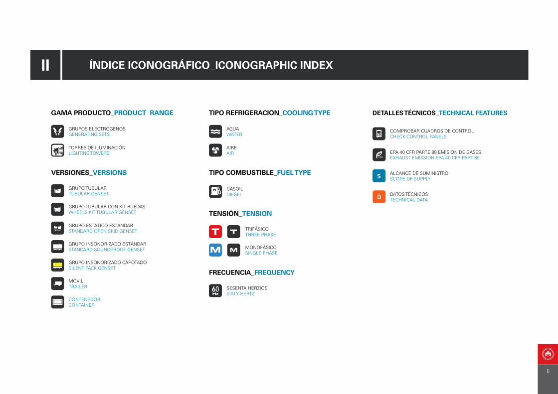
II ÍNDICE ICONOGRÁFICO_ICONOGRAPHIC INDEX
TIPO REFRIGERACION_COOLING TYPE
AIREAIR
TIPO COMBUSTIBLE_FUEL TYPE
GASOILDIESEL
TENSIÓN_TENSION
TRIFÁSICOTHREE PHASE
MONOFÁSICOSINGLE PHASE
AGUAWATER
FRECUENCIA_FREQUENCY
SESENTA HERZIOSSIXTY HERTZ
GAMA PRODUCTO_PRODUCT RANGE
GRUPOS ELECTRÓGENOSGENERATING SETS
TORRES DE ILUMINACIÓNLIGHTING TOWERS
VERSIONES_VERSIONS
GRUPO TUBULAR TUBULAR GENSET
GRUPO TUBULAR CON KIT RUEDASWHEELS KIT TUBULAR GENSET
GRUPO ESTÁTICO ESTÁNDAR STANDARD OPEN SKID GENSET
GRUPO INSONORIZADO ESTÁNDARSTANDARD SOUNDPROOF GENSET
MÓVILTRAILER
GRUPO INSONORIZADO CAPOTADOSILENT PACK GENSET
CONTENEDORCONTAINER
DETALLES TÉCNICOS_TECHNICAL FEATURES
COMPROBAR CUADROS DE CONTROL CHECK CONTROL PANELS
EPA 40 CFR PARTE 89 EMISION DE GASESEXHAUST EMISSION EPA 40 CFR PART 89
S ALCANCE DE SUMINISTRO SCOPE OF SUPPLY
D DATOS TÉCNICOS TECHNICAL DATA
5

HIMOINSA POWER SYSTEMS
HIMOINSA HEADQUARTER
HIMOINSA
TRATAMIENTO METAL1
TREATMENT METAL1
HIMOINSA
TRATAMIENTO METAL2
TREATMENT METAL2
GENELEC S.A.S
HIMOINSA
PVT LTD
HIMOINSA
CHINA
HIMOINSA MIDDLE
EAST FZE
HIMOINSA
DEUTSCHLAND
HIMOINSA
CENTRAL
ASIA
HIMOINSA ITALIA
HIMOINSA POLSKA
HIMOINSA
MEXICO
HIMOINSA
PANAMA
HIMOINSA LATINOAMERICA
HIMOINSA
FAR EAST
HIMOINSA
PORTUGAL
Fábricas | Factories Filiales | Subisidiaries
7 plantas productivas y 10 filiales. Presente en cinco continentes y en más de 100 países.7 production centers and 10 subsidiaries. Present in 5 continents and i n over 100 countries.
HIMOINSA EN EL MUNDO | HIMOINSA AROUND THE WORLD
6
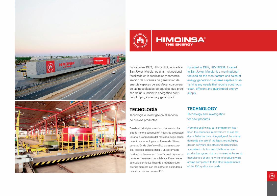
Fundada en 1982, HIMOINSA, ubicada en San Javier, Murcia, es una multinacional focalizada en la fabricación y comercia-lización de sistemas de generación de energía capaces de satisfacer cualquiera de las necesidades de aquellos que preci-san de un suministro energético conti-nuo, limpio, eficiente y garantizado.
TECNOLOGÍATecnología e investigación al servicio
de nuevos productos
Desde el principio, nuestro compromiso ha
sido la mejora continua en nuestros productos.
Estar a la vanguardia del mercado exige el uso
de últimas tecnologías; software de última
generación de diseño y cálculos estructura-
les, robótica especializada y un sistema de
producción totalmente automatizado que nos
permiten culminar con la fabricación en serie
de cualquier nueva línea de productos cum-
pliendo siempre con los estrictos estándares
de calidad de las normas ISO.
Founded in 1982, HIMOINSA, located in San Javier, Murcia, is a multinational focused on the manufacture and sales of energy generation systems capable of sa-tisfying any needs that require continous, clean, efficient and guaranteed energy supply.
TECHNOLOGYTechnology and investigation
for new products
From the beginning, our commitment has
been the continous improvement of our pro-
ducts. To be on the cutting-edge of the market
demands the use of the latest technoligies;
design software and structural calculations,
specialized robotics and totally automated
production system that culminates in the serial
manufacture of any new line of products wich
always complies with the strict requirements
of the ISO quality standards.
7
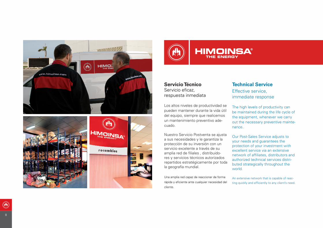
Servicio TécnicoServicio eficaz,respuesta inmediata
Los altos niveles de productividad se pueden mantener durante la vida útil del equipo, siempre que realicemos un mantenimiento preventivo ade-cuado.
Nuestro Servicio Postventa se ajusta a sus necesidades y le garantiza la protección de su inversión con un servicio excelente a través de su amplia red de filiales , distribuido-res y servicios técnicos autorizados repartidos estratégicamente por toda la geografía mundial.
Una amplia red capaz de reaccionar de forma
rápida y eficiente ante cualquier necesidad del
cliente.
Technical ServiceEffective service,immediate response
The high levels of productivity can be maintained during the life cycle of the equipment, whenever we carry out the necessary preventive mainte-nance.
Our Post-Sales Service adjusts to your needs and guarantees the protection of your investment with excellent service via an extensive network of affiliates, distributors and authorized technical services distri-buted strategically throughout the world.
An extensive network that is capable of reac-ting quickly and efficiently to any client’s need.
8
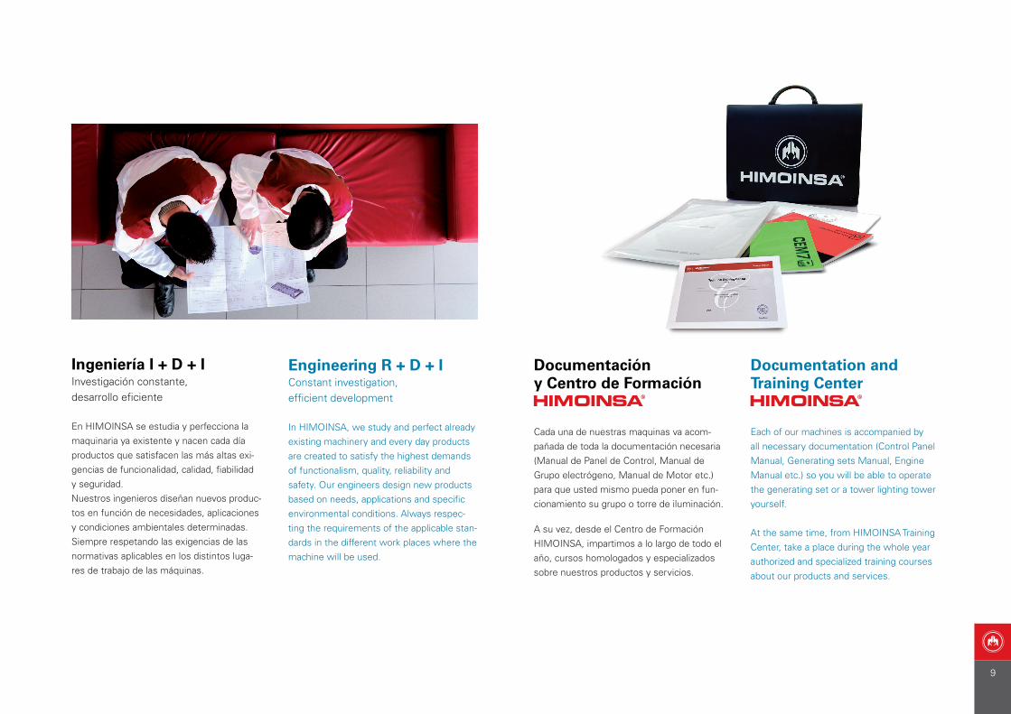
Ingeniería I + D + IInvestigación constante,desarrollo eficiente
En HIMOINSA se estudia y perfecciona la maquinaria ya existente y nacen cada día productos que satisfacen las más altas exi-gencias de funcionalidad, calidad, fiabilidad y seguridad.Nuestros ingenieros diseñan nuevos produc-tos en función de necesidades, aplicaciones y condiciones ambientales determinadas. Siempre respetando las exigencias de las normativas aplicables en los distintos luga-res de trabajo de las máquinas.
Engineering R + D + IConstant investigation,efficient development
In HIMOINSA, we study and perfect already existing machinery and every day products are created to satisfy the highest demands of functionalism, quality, reliability and safety. Our engineers design new products based on needs, applications and specific environmental conditions. Always respec-ting the requirements of the applicable stan-dards in the different work places where the machine will be used.
Documentación y Centro de Formación
Cada una de nuestras maquinas va acom-pañada de toda la documentación necesaria (Manual de Panel de Control, Manual de Grupo electrógeno, Manual de Motor etc.) para que usted mismo pueda poner en fun-cionamiento su grupo o torre de iluminación.
A su vez, desde el Centro de Formación HIMOINSA, impartimos a lo largo de todo el año, cursos homologados y especializados sobre nuestros productos y servicios.
Documentation and Training Center
Each of our machines is accompanied by all necessary documentation (Control Panel Manual, Generating sets Manual, Engine Manual etc.) so you will be able to operate the generating set or a tower lighting tower yourself.
At the same time, from HIMOINSA Training Center, take a place during the whole year authorized and specialized training courses about our products and services.
9
08
GA
MA
PE
SAD
A |
HE
AV
Y R
AN
GE
10

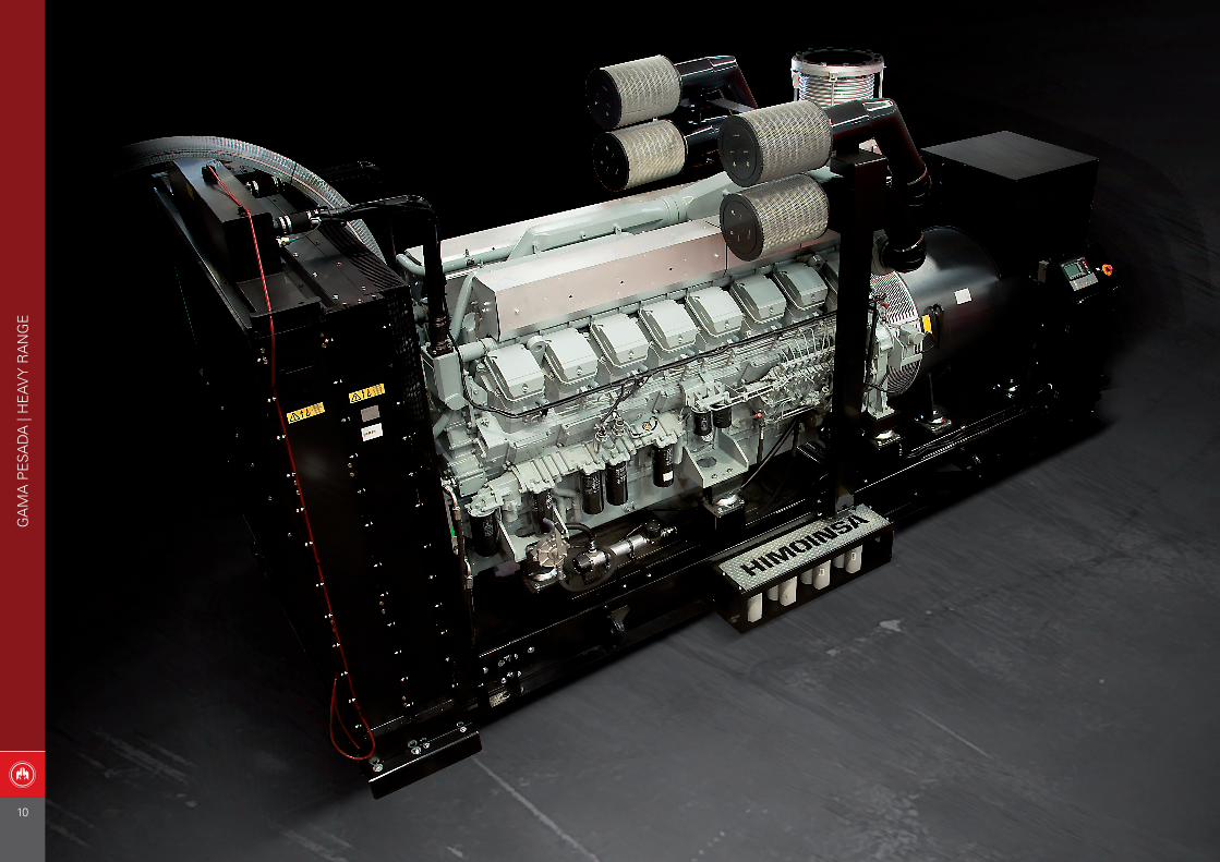
APLICACIONES_APPLICATIONS:
Obras Públicas_Public Building SitesIndustrias_Industries
Construcción_ConstructionAeropuertos_AirportsHospitales_Hospitals
Comunicaciones_Communications
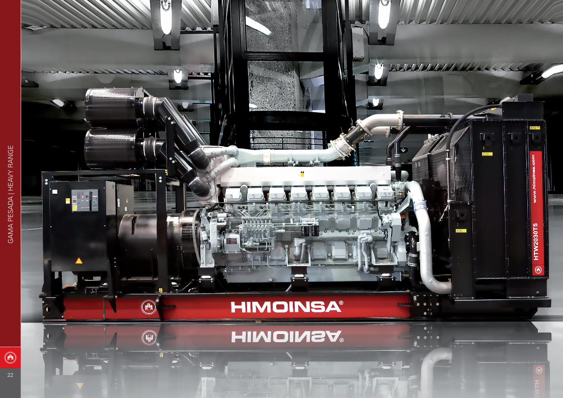
HTWHMW
SERIES: Powered by: MITSUBISHI
Powered by: MTU
GA
MA
PE
SAD
A |
HE
AV
Y R
AN
GE
GAMA PESADAHEAVY RANGE
11
MOTOR_ENGINE HTW HMW
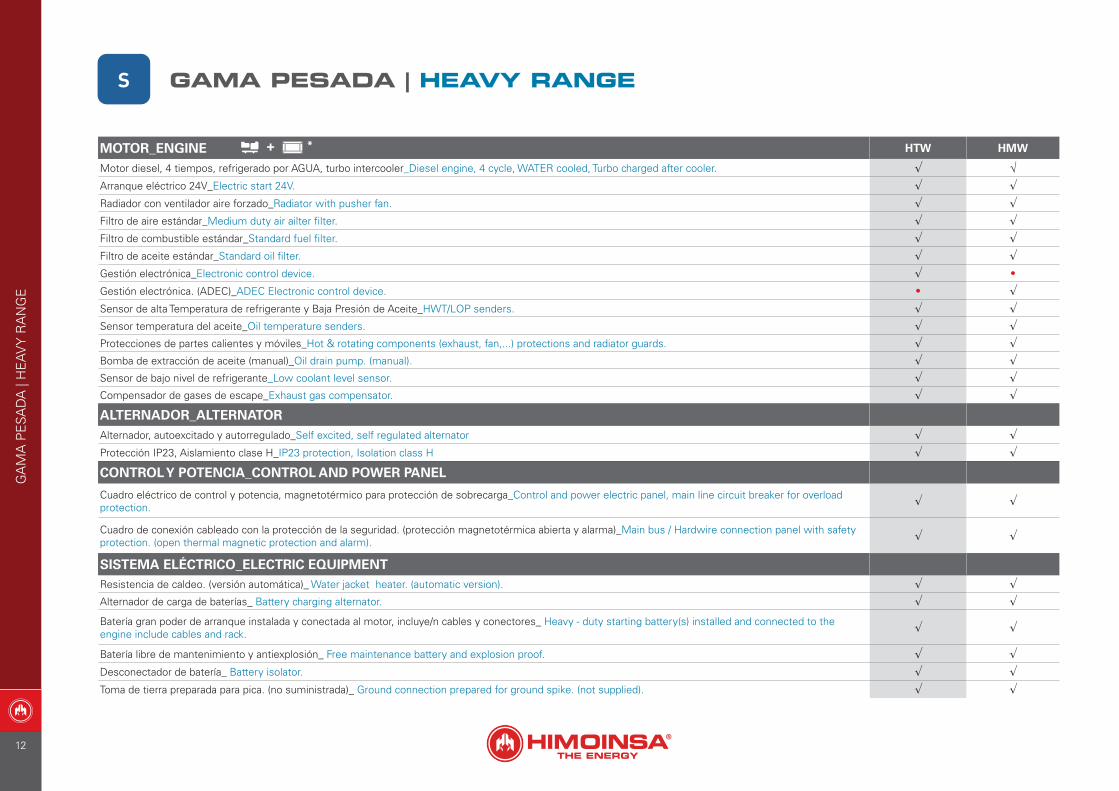
Motor diesel, 4 tiempos, refrigerado por AGUA, turbo intercooler_Diesel engine, 4 cycle, WATER cooled, Turbo charged after cooler. √ √ Arranque eléctrico 24V_Electric start 24V. √ √Radiador con ventilador aire forzado_Radiator with pusher fan. √ √Filtro de aire estándar_Medium duty air ailter filter. √ √Filtro de combustible estándar_Standard fuel filter. √ √Filtro de aceite estándar_Standard oil filter. √ √Gestión electrónica_Electronic control device. √ •
Gestión electrónica. (ADEC)_ADEC Electronic control device. • √Sensor de alta Temperatura de refrigerante y Baja Presión de Aceite_HWT/LOP senders. √ √Sensor temperatura del aceite_Oil temperature senders. √ √Protecciones de partes calientes y móviles_Hot & rotating components (exhaust, fan,...) protections and radiator guards. √ √Bomba de extracción de aceite (manual)_Oil drain pump. (manual). √ √Sensor de bajo nivel de refrigerante_Low coolant level sensor. √ √Compensador de gases de escape_Exhaust gas compensator. √ √
ALTERNADOR_ALTERNATORAlternador, autoexcitado y autorregulado_Self excited, self regulated alternator √ √Protección IP23, Aislamiento clase H_IP23 protection, Isolation class H √ √
CONTROL Y POTENCIA_CONTROL AND POWER PANEL
Cuadro eléctrico de control y potencia, magnetotérmico para protección de sobrecarga_Control and power electric panel, main line circuit breaker for overload protection. √ √
Cuadro de conexión cableado con la protección de la seguridad. (protección magnetotérmica abierta y alarma)_Main bus / Hardwire connection panel with safety protection. (open thermal magnetic protection and alarm). √ √
SISTEMA ELÉCTRICO_ELECTRIC EQUIPMENTResistencia de caldeo. (versión automática)_ Water jacket heater. (automatic version). √ √Alternador de carga de baterías_ Battery charging alternator. √ √
Batería gran poder de arranque instalada y conectada al motor, incluye/n cables y conectores_ Heavy - duty starting battery(s) installed and connected to the engine include cables and rack. √ √
Batería libre de mantenimiento y antiexplosión_ Free maintenance battery and explosion proof. √ √Desconectador de batería_ Battery isolator. √ √Toma de tierra preparada para pica. (no suministrada)_ Ground connection prepared for ground spike. (not supplied). √ √
+ *
S GAMA PESADA | HEAVY RANGE
GA
MA
PE
SAD
A |
HE
AV
Y R
AN
GE
12
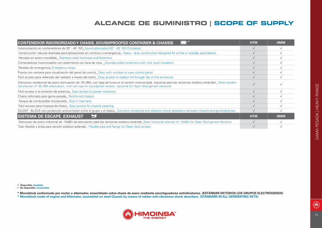
* Monoblock conformado por motor y alternador, ensamblado sobre chasis de acero mediante amortiguadores antivibratorios. (ESTÁNDAR EN TODOS LOS GRUPOS ELECTRÓGENOS)* Monoblock made of engine and Alternator, assembled on steel Chassis by means of rubber anti-vibrations shock absorbers. (STANDARD IN ALL GENERATING SETS)
CONTENEDOR INSONORIZADO Y CHASIS_SOUNDPROOFED CONTAINER & CHASSIS HTW HMW
Insonorización en contenedores de 20’ - 40’ ISO_Sound attenuated 20’ - 40’ ISO Container. √ √Construcción robusta diseñada para aplicaciones en continuo o emergencia_ Heavy - duty construction designed for prime or standby applications. √ √Herrajes en acero inoxidable_ Stainless steel hardware and fasteners. √ √Contenedores insonorizados con aislamiento con lana de roca, _Soundproofed containers with rock wool insulation. √ √Paradas de emergencia_Emergency stops. √ √Puerta con ventana para visualización del panel de control_ Door with window to view control panel. √ √Fácil acceso para rellenado del radiador a través del techo_ Easy access to radiator fill through top of the enclosure. √ √Silencioso residencial de acero atenuación de -35 dBA, con tapa de lluvia en la versión insonorizada. (opcional para las versiones estático estándar)_ Steel residen-tial silencer of -35 dBA attenuation, with rain cap for soundproof version. (optional for Open Skid genset versions) √ √
Fácil acceso a la conexión de potencia_ Easy access to power conection. √ √Chasis reforzado para gama pesada_ Reinforced chassis √ √Tanque de combustible incorporado_ Built in fuel tank. √ √Fácil acceso para limpieza de chasis_ Easy access for chassis cleaning. √ √SILENT - BLOCK con protección anticorrosión entre el grupo y el chasis_ Corrosion protected anti-vibration shock absorbers between chassis and generating set. √ √
SISTEMA DE ESCAPE_EXHAUST HTW HMW
Silencioso de acero industrial de -15dBA de atenuación para las versiones estático estándar_Steel Industrial silencer of -15dBA for Open Skid genset Versions. √ √Tubo flexible y brida para versión estático estándar_ Flexible pipe and flange for Open Skid version. √ √
√ Disponible_Available• No disponible_Unavailable
*
ALCANCE DE SUMINISTRO | SCOPE OF SUPPLY
GA
MA
PE
SAD
A |
HE
AV
Y R
AN
GE
13
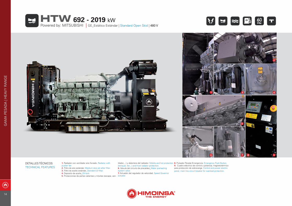
1. Radiador con ventilador aire forzado. Radiator with pusher fan2. Filtro de aire estándar. Medium duty air ailter filter.3. Filtro de aceite estándar_Standard oil filter.4. Deposito de aceite_Oil tank.5. Protecciones de partes calientes y móviles (escape, ven-
tilador,...) y delantera del radiador. Mobile and hot protection (exhaust, fan...) and front radiator protection.6. Valvula del circuito de precaldeo_Water preheating system valve.7. Actuador del regulador de velocidad. Speed Governor actuator.
8. Pulsador Parada Emergencia. Emergency Push Button.9. Cuadro eléctrico de control y potencia, magnetotérmico para protección de sobrecarga. Control and power electric panel, main line circuit breaker for overload protection.
6 7
1
5
3
2
4
8 9
GA
MA
PE
SAD
A |
HE
AV
Y R
AN
GE
Powered by: MITSUBISHI | GE_Estático Estándar | Standard Open Skid | 480 V692 - 2019 kWHTW
DETALLES TÉCNICOSTECHNICAL FEATURES
14
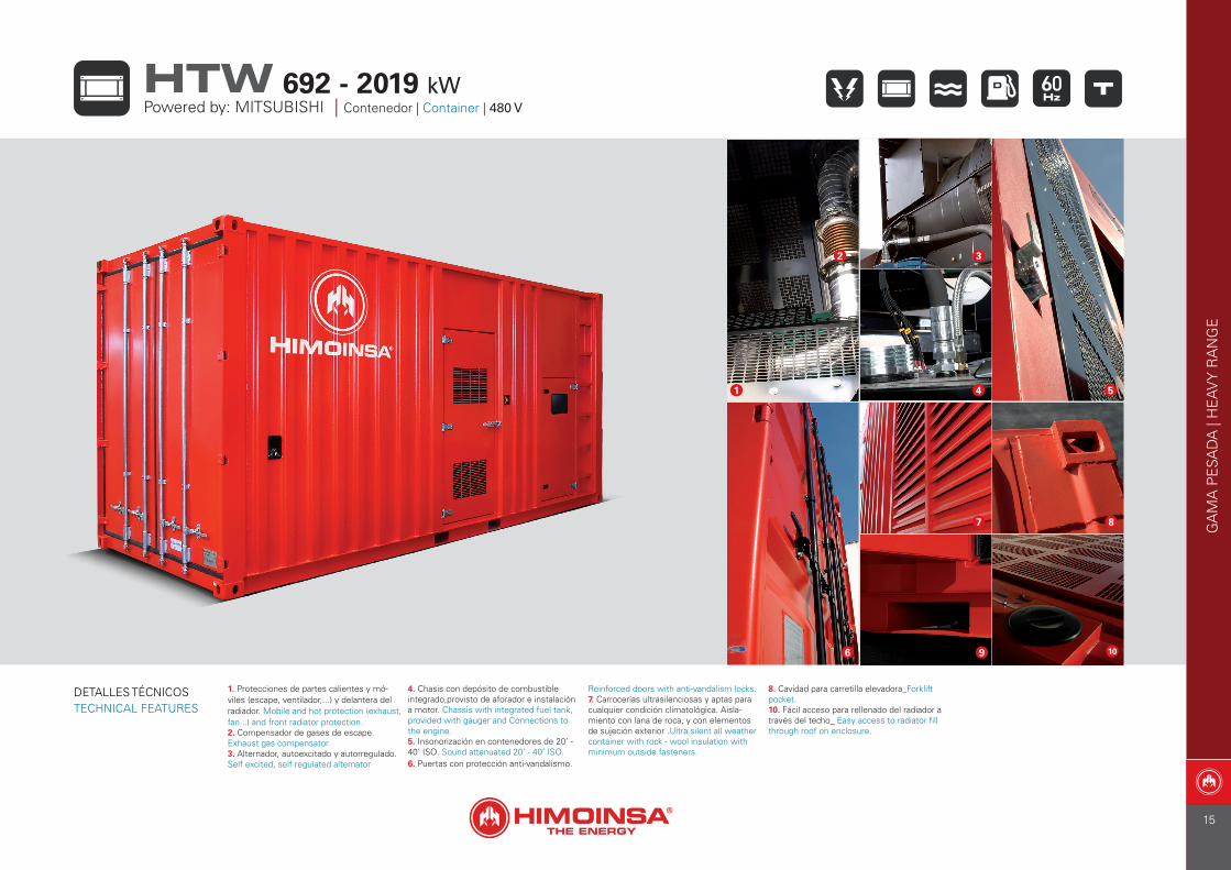
1. Protecciones de partes calientes y mó-viles (escape, ventilador,...) y delantera del radiador. Mobile and hot protection (exhaust, fan...) and front radiator protection.2. Compensador de gases de escape. Exhaust gas compensator.3. Alternador, autoexcitado y autorregulado. Self excited, self regulated alternator
4. Chasis con depósito de combustible integrado,provisto de aforador e instalación a motor. Chassis with integrated fuel tank, provided with gauger and Connections to the engine.5. Insonorización en contenedores de 20’ - 40’ ISO. Sound attenuated 20’ - 40’ ISO.6. Puertas con protección anti-vandalismo.
Reinforced doors with anti-vandalism locks.7. Carrocerías ultrasilenciosas y aptas para cualquier condición climatológica. Aisla-miento con lana de roca, y con elementos de sujeción exterior .Ultra silent all weather container with rock - wool insulation with minimum outside fasteners.
8. Cavidad para carretilla elevadora_Forklift pocket.10. Fácil acceso para rellenado del radiador a través del techo_ Easy access to radiator fill through roof on enclosure.
1
2 3
54
6
8
9 10
7 GA
MA
PE
SAD
A |
HE
AV
Y R
AN
GE
692 - 2019 kWHTWPowered by: MITSUBISHI | Contenedor | Container | 480 V
DETALLES TÉCNICOSTECHNICAL FEATURES
15
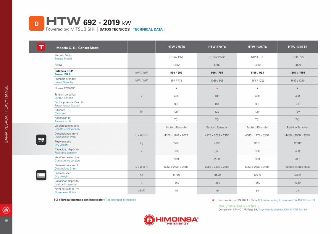
Modelo G. E. | Genset Model HTW-775 T6 HTW-870 T6 HTW-1025 T6 HTW-1215 T6
Modelo MotorEngine Model S12A2 PTA S12A2 PTA2 S12H PTA S12R PTA
R.P.M. 1.800 1.800 1.800 1.800
Potencia P.R.P. Power P.R.P.
kVA / kW 864 / 692 986 / 789 1166 / 933 1361 / 1089
Potencia StandbyPower Standby
kVA / kW 967 / 773 1085 / 868 1281 / 1025 1513 / 1210
Norma 97/68/EC • • • •
Tensión de salidaOutput voltage
V 480 480 480 480
Factor potencia Cos phiPower factor Cos phi 0,8 0,8 0,8 0,8
CilindrosCylindres
Nº 12V 12V 12V 12V
Aspiración (1)Aspiration (1) TCI TCI TCI TCI
Versión constructivaConstructive version Estático Estandar Estático Estandar Estático Estandar Estático Estandar
Dimensiones (mm)Dimensions (mm)
L x W x H 4150 x 1748 x 2077 4270 x 2022 x 2150 4500 x 1773 x 2391 4450 x 2050 x 2335
Peso en secoDry Weight
Kg 7750 7800 9610 12000
Capacidad depósitoFuel tank capacity
L 300 350 350 400
Versión constructivaConstructive version 20 ft 20 ft 20 ft 20 ft
Dimensiones (mm)Dimensions (mm)
L x W x H 6058 x 2438 x 2896 6058 x 2438 x 2896 6058 x 2438 x 2896 6058 x 2438 x 2896
Peso en secoDry Weight
Kg 11750 11800 13610 12644
Capacidad depósitoFuel tank capacity
L 1350 1350 1350 1350
Nivel de ruido @ 7mNoise level @ 7m
dB(A) 78 79 84 77
TCI = Turboalimentado con intercooler / Turbocharged intercooled
GA
MA
PE
SAD
A |
HE
AV
Y R
AN
GE
DPowered by: MITSUBISHI | DATOS TECNICOS | TECHNICAL DATA |
692 - 2019 kWHTW
• No cumple con EPA 40 CFR Parte 89 / Not according to directive EPA 40 CFR Part 89
TIER II, TIER III, TIER IV, INT. TIER IVCumple con EPA 40 CFR Parte 89 / According to directive EPA 40 CFR Part 89
16
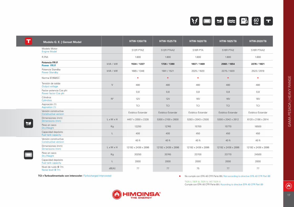
Modelo G. E. | Genset Model HTW-1350 T6 HTW-1525 T6 HTW-1620 T6 HTW-1825 T6 HTW-2020 T6
Modelo MotorEngine Model S12R PTA2 S12R PTAA2 S16R PTA S16R PTA2 S16R PTAA2
R.P.M. 1.800 1.800 1.800 1.800 1.800
Potencia P.R.P. Power P.R.P.
kVA / kW 1534 / 1227 1726 / 1380 1837 / 1469 2068 / 1654 2276 / 1821
Potencia StandbyPower Standby
kVA / kW 1685 / 1348 1901 / 1521 2025 / 1620 2275 / 1820 2523 / 2019
Norma 97/68/EC • • • • •
Tensión de salidaOutput voltage
V 480 480 480 480 480
Factor potencia Cos phiPower factor Cos phi 0,8 0,8 0,8 0,8 0,8
CilindrosCylindres
Nº 12V 12V 16V 16V 16V
Aspiración (1)Aspiration (1) TCI TCI TCI TCI TCI
Versión constructivaConstructive version Estático Estandar Estático Estandar Estático Estandar Estático Estandar Estático Estandar
Dimensiones (mm)Dimensions (mm)
L x W x H 4457 x 2050 x 2328 5300 x 2100 x 2600 5283 x 2043 x 2500 5300 x 2042 x 2612 6120 x 2190 x 2814
Peso en secoDry Weight
Kg 12250 12745 15700 15770 16500
Capacidad depósitoFuel tank capacity
L 400 400 450 450 450
Versión constructivaConstructive version 40 ft 40 ft 40 ft 40 ft 40 ft
Dimensiones (mm)Dimensions (mm)
L x W x H 12192 x 2438 x 2896 12192 x 2438 x 2896 12192 x 2438 x 2896 12192 x 2438 x 2896 12192 x 2438 x 2896
Peso en secoDry Weight
Kg 20250 20745 23700 23770 24500
Capacidad depósitoFuel tank capacity
L 2000 2000 2000 2000 2000
Nivel de ruido @ 7mNoise level @ 7m
dB(A) 77 77 75 77 77
TCI = Turboalimentado con intercooler / Turbocharged intercooled
GA
MA
PE
SAD
A |
HE
AV
Y R
AN
GE
• No cumple con EPA 40 CFR Parte 89 / Not according to directive EPA 40 CFR Part 89
TIER II, TIER III, TIER IV, INT. TIER IVCumple con EPA 40 CFR Parte 89 / According to directive EPA 40 CFR Part 89
17
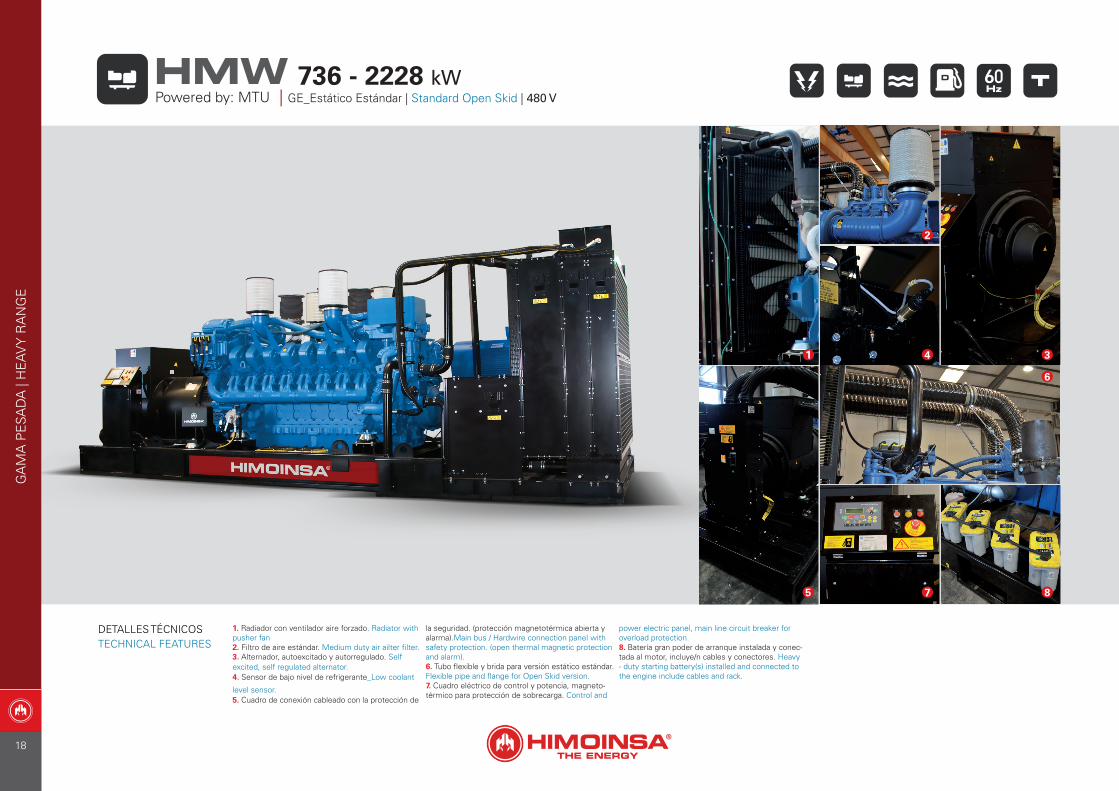
1. Radiador con ventilador aire forzado. Radiator with pusher fan2. Filtro de aire estándar. Medium duty air ailter filter.3. Alternador, autoexcitado y autorregulado. Self excited, self regulated alternator.4. Sensor de bajo nivel de refrigerante_Low coolant
level sensor.5. Cuadro de conexión cableado con la protección de
la seguridad. (protección magnetotérmica abierta y alarma).Main bus / Hardwire connection panel with safety protection. (open thermal magnetic protection and alarm).6. Tubo flexible y brida para versión estático estándar. Flexible pipe and flange for Open Skid version.7. Cuadro eléctrico de control y potencia, magneto-térmico para protección de sobrecarga. Control and
power electric panel, main line circuit breaker for overload protection. 8. Batería gran poder de arranque instalada y conec-tada al motor, incluye/n cables y conectores. Heavy - duty starting battery(s) installed and connected to the engine include cables and rack.
DETALLES TÉCNICOSTECHNICAL FEATURES
1
2
34
8
6
75
GA
MA
PE
SAD
A |
HE
AV
Y R
AN
GE
Powered by: MTU | GE_Estático Estándar | Standard Open Skid | 480 V736 - 2228 kWHMW
18
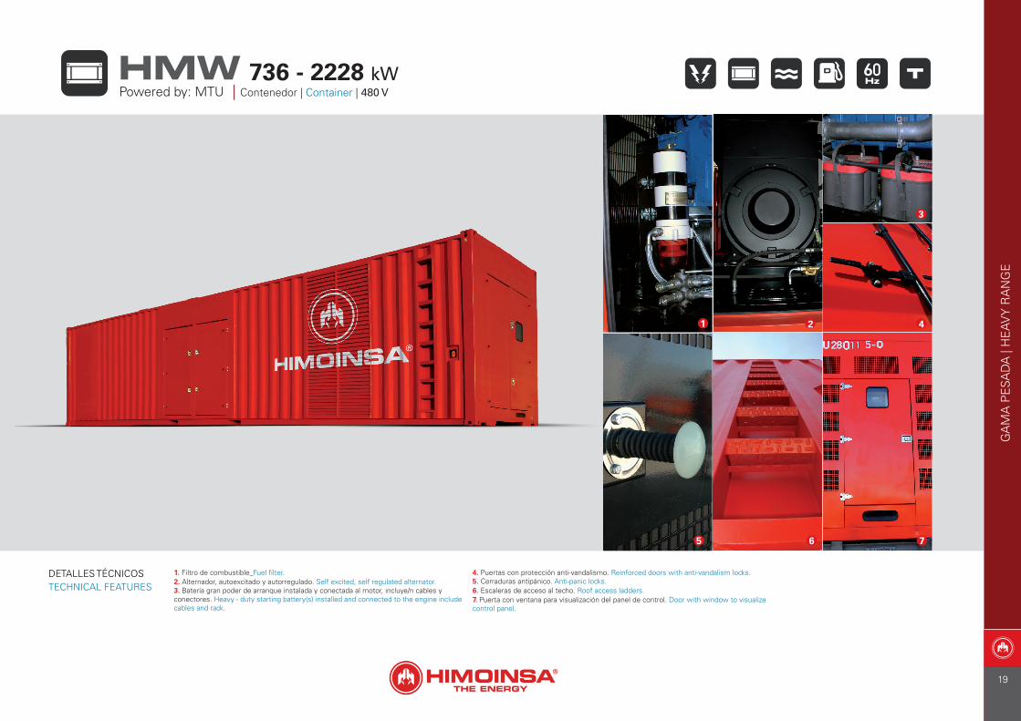
1. Filtro de combustible_Fuel filter.2. Alternador, autoexcitado y autorregulado. Self excited, self regulated alternator.3. Batería gran poder de arranque instalada y conectada al motor, incluye/n cables y conectores. Heavy - duty starting battery(s) installed and connected to the engine include cables and rack.
4. Puertas con protección anti-vandalismo. Reinforced doors with anti-vandalism locks.5. Cerraduras antipánico. Anti-panic locks. 6. Escaleras de acceso al techo. Roof access ladders.7. Puerta con ventana para visualización del panel de control. Door with window to visualize control panel.
DETALLES TÉCNICOSTECHNICAL FEATURES
1 2
3
6 7
4
5
GA
MA
PE
SAD
A |
HE
AV
Y R
AN
GE
Powered by: MTU | Contenedor | Container | 480 V736 - 2228 kWHMW
19
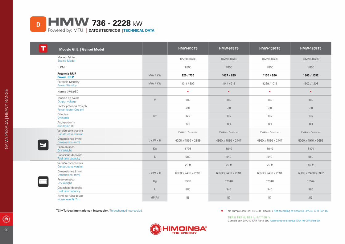
Modelo G. E. | Genset Model HMW-810 T6 HMW-915 T6 HMW-1020 T6 HMW-1205 T6
Modelo MotorEngine Model 12V2000G85 16V2000G45 16V2000G85 18V2000G85
R.P.M. 1.800 1.800 1.800 1.800
Potencia P.R.P. Power P.R.P.
kVA / kW 920 / 736 1037 / 829 1150 / 920 1365 / 1092
Potencia StandbyPower Standby
kVA / kW 1011 / 809 1144 / 915 1269 / 1015 1503 / 1203
Norma 97/68/EC • • • •
Tensión de salidaOutput voltage
V 480 480 480 480
Factor potencia Cos phiPower factor Cos phi 0,8 0,8 0,8 0,8
CilindrosCylindres
Nº 12V 16V 16V 18V
Aspiración (1)Aspiration (1) TCI TCI TCI TCI
Versión constructivaConstructive version
Estático Estandar Estático Estandar Estático Estandar Estático Estandar
Dimensiones (mm)Dimensions (mm)
L x W x H 4208 x 1836 x 2389 4950 x 1836 x 2447 4950 x 1836 x 2447 5050 x 1910 x 2652
Peso en secoDry Weight
Kg 5798 6840 8040 8474
Capacidad depósitoFuel tank capacity
L 980 940 940 980
Versión constructivaConstructive version 20 ft 20 ft 20 ft 40 ft
Dimensiones (mm)Dimensions (mm)
L x W x H 6058 x 2438 x 2591 6058 x 2438 x 2591 6058 x 2438 x 2591 12192 x 2438 x 3902
Peso en secoDry Weight
Kg 9598 12340 12340 15574
Capacidad depósitoFuel tank capacity
L 980 940 940 980
Nivel de ruido @ 7mNoise level @ 7m
dB(A) 88 87 87 86
TCI = Turboalimentado con intercooler / Turbocharged intercooled
GA
MA
PE
SAD
A |
HE
AV
Y R
AN
GE
D 736 - 2228 kWHMWPowered by: MTU | DATOS TECNICOS | TECHNICAL DATA |
• No cumple con EPA 40 CFR Parte 89 / Not according to directive EPA 40 CFR Part 89
TIER II, TIER III, TIER IV, INT. TIER IVCumple con EPA 40 CFR Parte 89 / According to directive EPA 40 CFR Part 89
20
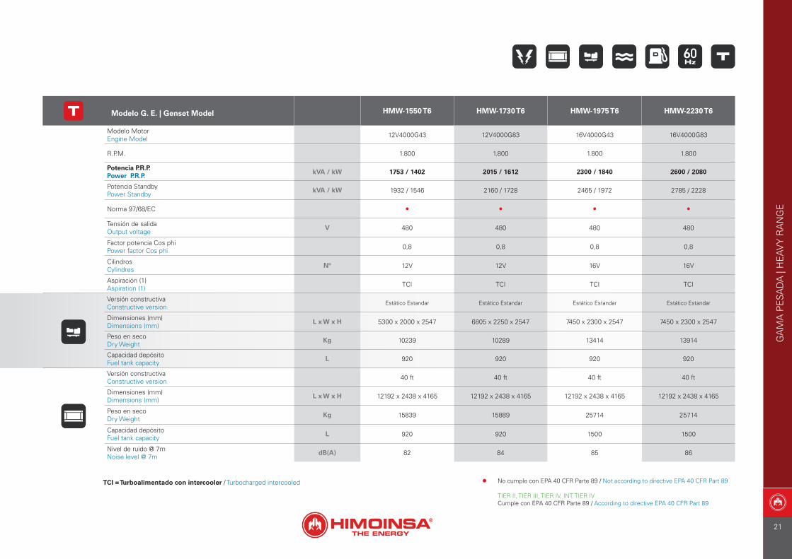
Modelo G. E. | Genset Model HMW-1550 T6 HMW-1730 T6 HMW-1975 T6 HMW-2230 T6
Modelo MotorEngine Model 12V4000G43 12V4000G83 16V4000G43 16V4000G83
R.P.M. 1.800 1.800 1.800 1.800
Potencia P.R.P. Power P.R.P.
kVA / kW 1753 / 1402 2015 / 1612 2300 / 1840 2600 / 2080
Potencia StandbyPower Standby
kVA / kW 1932 / 1546 2160 / 1728 2465 / 1972 2785 / 2228
Norma 97/68/EC • • • •
Tensión de salidaOutput voltage
V 480 480 480 480
Factor potencia Cos phiPower factor Cos phi 0,8 0,8 0,8 0,8
CilindrosCylindres
Nº 12V 12V 16V 16V
Aspiración (1)Aspiration (1) TCI TCI TCI TCI
Versión constructivaConstructive version
Estático Estandar Estático Estandar Estático Estandar Estático Estandar
Dimensiones (mm)Dimensions (mm)
L x W x H 5300 x 2000 x 2547 6805 x 2250 x 2547 7450 x 2300 x 2547 7450 x 2300 x 2547
Peso en secoDry Weight
Kg 10239 10289 13414 13914
Capacidad depósitoFuel tank capacity
L 920 920 920 920
Versión constructivaConstructive version 40 ft 40 ft 40 ft 40 ft
Dimensiones (mm)Dimensions (mm)
L x W x H 12192 x 2438 x 4165 12192 x 2438 x 4165 12192 x 2438 x 4165 12192 x 2438 x 4165
Peso en secoDry Weight
Kg 15839 15889 25714 25714
Capacidad depósitoFuel tank capacity
L 920 920 1500 1500
Nivel de ruido @ 7mNoise level @ 7m
dB(A) 82 84 85 86
TCI = Turboalimentado con intercooler / Turbocharged intercooled
GA
MA
PE
SAD
A |
HE
AV
Y R
AN
GE
• No cumple con EPA 40 CFR Parte 89 / Not according to directive EPA 40 CFR Part 89
TIER II, TIER III, TIER IV, INT. TIER IVCumple con EPA 40 CFR Parte 89 / According to directive EPA 40 CFR Part 89
21
GA
MA
PE
SAD
A |
HE
AV
Y R
AN
GE
22
GA
MA
IND
UST
RIA
L | I
ND
UST
RIA
L R
AN
GE
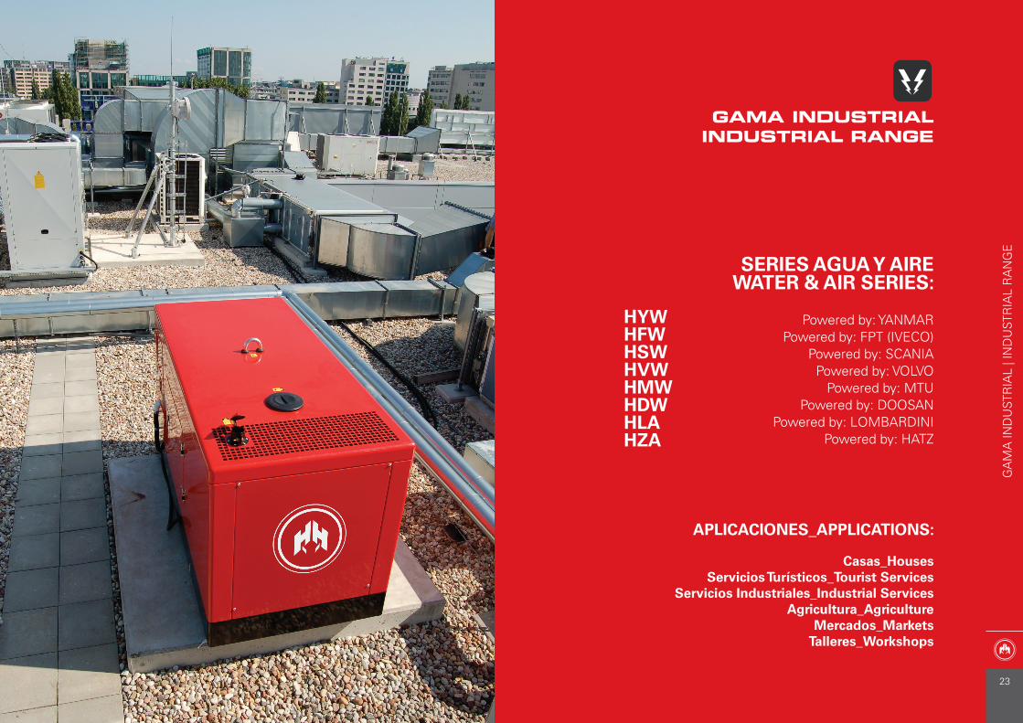
GAMA INDUSTRIALINDUSTRIAL RANGE
APLICACIONES_APPLICATIONS:
Casas_HousesServicios Turísticos_Tourist Services
Servicios Industriales_Industrial ServicesAgricultura_Agriculture
Mercados_MarketsTalleres_Workshops
SERIES AGUA Y AIREWATER & AIR SERIES:
Powered by: YANMARPowered by: FPT (IVECO)
Powered by: SCANIAPowered by: VOLVO
Powered by: MTUPowered by: DOOSAN
Powered by: LOMBARDINIPowered by: HATZ
HYWHFWHSWHVWHMWHDWHLAHZA
23
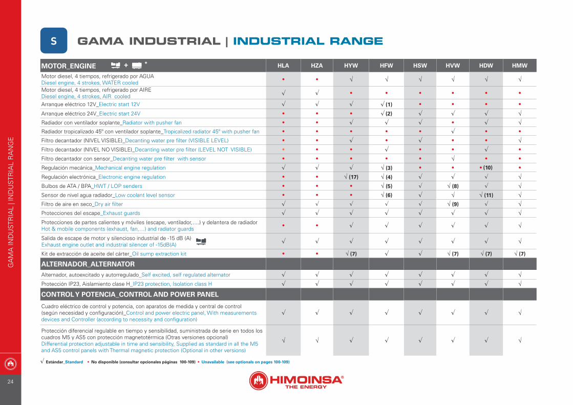
MOTOR_ENGINE HLA HZA HYW HFW HSW HVW HDW HMW
Motor diesel, 4 tiempos, refrigerado por AGUADiesel engine, 4 strokes, WATER cooled
• • √ √ √ √ √ √
Motor diesel, 4 tiempos, refrigerado por AIREDiesel engine, 4 strokes, AIR cooled √ √ • • • • • •
Arranque eléctrico 12V_Electric start 12V √ √ √ √ (1) • • • •
Arranque eléctrico 24V_Electric start 24V • • • √ (2) √ √ √ √Radiador con ventilador soplante_Radiator with pusher fan • • √ √ √ • √ √Radiador tropicalizado 45º con ventilador soplante_Tropicalized radiator 45º with pusher fan • • • • • √ • •
Filtro decantador (NIVEL VISIBLE)_Decanting water pre filter (VISIBLE LEVEL) • • √ • √ • • √Filtro decantador (NIVEL NO VISIBLE)_Decanting water pre filter (LEVEL NOT VISIBLE) • • • √ • • √ •
Filtro decantador con sensor_Decanting water pre filter with sensor • • • • • √ • •
Regulación mecánica_Mechanical engine regulation √ √ √ √ (3) • • • (10) •
Regulación electrónica_Electronic engine regulation • • √ (17) √ (4) √ √ √ √Bulbos de ATA / BPA_HWT / LOP senders • • • √ (5) √ √ (8) √ √Sensor de nivel agua radiador_Low coolant level sensor • • • √ (6) √ √ √ (11) √Filtro de aire en seco_Dry air filter √ √ √ √ √ √ (9) √ √Protecciones del escape_Exhaust guards √ √ √ √ √ √ √ √Protecciones de partes calientes y móviles (escape, ventilador,….) y delantera de radiador Hot & mobile components (exhaust, fan,…) and radiator guards
• • √ √ √ √ √ √
Salida de escape de motor y silencioso industrial de -15 dB (A)Exhaust engine outlet and industrial silencer of -15dB(A) √ √ √ √ √ √ √ √
Kit de extracción de aceite del cárter_Oil sump extraction kit • • √ (7) √ √ √ (7) √ (7) √ (7)
ALTERNADOR_ALTERNATOR
Alternador, autoexcitado y autorregulado_Self excited, self regulated alternator √ √ √ √ √ √ √ √Protección IP23, Aislamiento clase H_IP23 protection, Isolation class H √ √ √ √ √ √ √ √
CONTROL Y POTENCIA_CONTROL AND POWER PANEL
Cuadro eléctrico de control y potencia, con aparatos de medida y central de control (según necesidad y configuración)_Control and power electric panel, With measurements devices and Controller (according to necessity and configuration)
√ √ √ √ √ √ √ √
Protección diferencial regulable en tiempo y sensibilidad, suministrada de serie en todos los cuadros M5 y AS5 con protección magnetotérmica (Otras versiones opcional)Differential protection adjustable in time and sensibility, Supplied as standard in all the M5 and AS5 control panels with Thermal magnetic protection (Optional in other versions)
√ √ √ √ √ √ √ √
+
√ Estándar_Standard • No disponible (consultar opcionales páginas 100-109) • Unavailable (see optionals on pages 100-109)
*
S GAMA INDUSTRIAL | INDUSTRIAL RANGE
GA
MA
IND
UST
RIA
L | I
ND
UST
RIA
L R
AN
GE
24
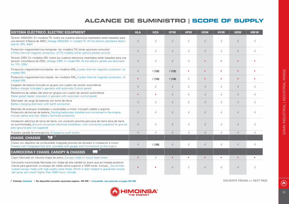
SISTEMA ELÉCTRICO_ELECTRIC EQUIPMENT HLA HZA HYW HFW HSW HVW HDW HM W
Tensión 400/230V. En modelos T5: todos los cuadros eléctricos reseñados están basados para una tensión trifásica de 400V_Voltage 400/230V. In models T5: All the electric panelsare descri-bed for 3Ph, 400V.
√ √ √ √ √ √ √ √
Protección magnetotérmica tetrapolar. (en modelos T5) (otras opciones consultar)4 Poles thermal magnetic protection. (in T5 models) (other options please consult) √ √ √ √ √ √ √ √
Tensión 230V. En modelos M5: todos los cuadros eléctricos reseñados están basados para una tensión monofásica de 230V_Voltage 230V. In model M5: All the electric panels are described for 1Ph, 230V.
√ √ √ √ • • • •
Protección magnetotérmica bipolar. (en modelos M5)_2 poles thermal magnetic protection. (in models M5) √ √ (12) √ (12) • • • • •
Protección magnetotérmica tripolar. (en modelos M5)_3 poles thermal magnetic protection. (in models M5)
• √ (13) √ (14) √ • • • •
Cargador de batería (incluido en grupos con cuadro de versión automática)Battery charger (included in gensets with automatic Control panel) √ √ √ √ √ √ √ √
Resistencia de caldeo (de serie en grupos con cuadro de versión automática)Water jacket heater. (standard in gensets with automatic control panel)
• • √ √ √ √ √ √
Alternador de carga de baterías con toma de tierraBattery charging alternator with earth connection √ √ √ √ √ √ √ √
Batería/s de arranque instaladas y conectadas a motor, incluye/n cables y soporte.Protección de bornas de batería_Starting battery/ies installed and connected to the engine. Include cables and rack. Battery terminals protection.
√ √ √ √ √ √ √ √
Instalación eléctrica de toma de tierra, con conexión prevista para pica de tierra (pica de tierra no suministrada)_Ground connection electrical installation, with connection prepared for ground pike (ground pike not supplied)
√ √ √ √ √ √ √ √
Pulsador parada de emergencia_Emergency push button √ √ √ √ √ √ √ √
CHASIS_CHASSIS Chasis con depósito de combustible integrado,provisto de aforador e instalación a motor Chassis with integrated fuel tank, provided with gauger and Connections to the engine √ √ (15) √ √ √ √ √ √
CARROCERIA Y CHASIS_CANOPY & CHASSIS
Capot fabricado en robusta chapa de acero_Canopy made of robust steel sheet. • √ • • • • • •
Carrocería insonorizada fabricada con chapa de alta calidad en acero que es tratada posterior-mente para garantizar un ensayo de niebla salina superior a 1000 horas. Incluye:_ Sound Atte-nuated canopy made with high quality steel sheet, Which is later treated to guarantee neutral salt spray test result Higher than 1000 hours. Include:
• • √ √ √ √ √ √
SIGUIENTE PÁGINA >> NEXT PAGE√ Estándar_Standard • No disponible (consultar opcionales páginas 100-109) • Unavailable (see optionals on pages 100-109)
*
*
ALCANCE DE SUMINISTRO | SCOPE OF SUPPLY
GA
MA
IND
UST
RIA
L | I
ND
UST
RIA
L R
AN
GE
25
CARROCERIA Y CHASIS_CANOPY & CHASSIS HLA HZA HYW HFW HSW HVW HDW HVW HMW
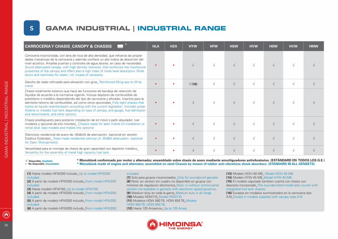
Carrocería insonorizada, con lana de roca de alta densidad, que refuerza las propie-dades mecánicas de la carrocería y además confiere un alto índice de absorción del nivel acústico. Amplias puertas y controles de agua /aceite, en caso de necesidad. Sound attenuated canopy, with high density rockwool, that reinforces the mechanical properties of the canopy and offers also a high index of noise level absorption. Wide doors and manholes for water / oil, incase of necessity.
• • √ √ √ √ √ √ √
Gancho de izado reforzado para elevación con grúa_ Reinforced lifting eye to lift by crane.
• • √ (16) √ √ √ √ √ √
Chasis totalmente estanco que hace las funciones de bandeja de retención de líquidos de acuerdo a la normativa vigente. Incluye depósito de combustible de polietileno o metálico dependiendo del tipo de carrocería y aforador, insertos para la admisión-retorno de combustible, así como otros opcionales_Fully tight chassis that works as liquids retentionbasin according with the current legislation. Includes polye-thylene or metallic fuel tank depending on type of canopy, and gauge, fuel admission and returninserts, and other options.
• • √ √ √ √ √ √ √
Chasis predispuesto para posterior instalación de kit móvil o patín alquilador. (ver modelos y opcional de kits móviles)_ Chassis ready for later mobile kit installation or rental skid. (see models and mobile kits options)
• • √ √ √ √ √ √ √
Silencioso residencial de acero de -35db(A) de atenuación. (opcional en versión Estático Estándar)_ Steel made residential silencer of -35dBA attenuation. (optional for Open Skid gensets).
• • √ √ √ √ √ √ √
Versatilidad para el montaje de chasis de gran capacidad con depósito metálico_ Versatility for the assembly of metal high capacity fuel tank.
• • √ √ √ √ √ √ √
(1) Hasta modelo HFW200 incluido_Up to model HFW200included(2) A partir de modelo HFW250 incluido_From model HFW250included(3) Hasta modelo HFW155_Up to model HFW155(4) A partir de modelo HFW200 incluido_From model HFW200included(5) A partir de modelo HFW200 incluido_From model HFW200included(6) A partir de modelo HFW200 incluido_From model HFW200
included(7) Solo para grupos insonorizados_Only for soundproof gensets(8) Nota: en version sin cuadro no disponible en grupos conmotores de regulacion electronica_Note: in without control panelversion not available in gensets with electronic speed governor.(9) Medium duty en toda la gama_Medium duty in all range(10) Modelo HDW110_Model HDW110(11) Modelos HDW 560 T6, HDW 655 T6_ModelsHDW 560 T6, HDW 655 T6.(12) Hasta 125 Amperios_Up to 125 Amps
(13) Modelo HZA1-40 M6_ Model HZA1-40 M6(14) Modelo HYW 45 M6_Model HYW 45 M6(15) El modelo capotado tambien cuenta con chasis condeposito incorporado_The soundproofed model also counts withintegrated fuel tank chassis.(16) Excepto en modelos suministrados en la carroceria tipoA10_Except in models supplied with canopy type A10
* Monoblock conformado por motor y alternador, ensamblado sobre chasis de acero mediante amortiguadores antivibratorios. (ESTÁNDARD EN TODOS LOS G.E.)* Monoblock made of engine and alternator, assembled on steel Chassis by means of rubber anti-vibrations shock absorbers. (STANDARD IN ALL GENSETS)
√ Disponible_Available• No disponible_Unavailable
*
S GAMA INDUSTRIAL | INDUSTRIAL RANGE
GA
MA
IND
UST
RIA
L | I
ND
UST
RIA
L R
AN
GE
26
GA
MA
IND
UST
RIA
L | I
ND
UST
RIA
L R
AN
GE
27

1 3
2
4
7
8 9
65
GA
MA
IND
UST
RIA
L | I
ND
UST
RIA
L R
AN
GE
Powered by: YANMAR | GE_Estático Estándar | Standard Open Skid | 480 - 240 V4,8 - 44 kWHYW
1. Radiador con ventilador soplante. Radiator with pusher fan.2. Protecciones de partes calientes y móviles (escape, ventilador,...) y delantera del radiador. Mobile and hot protection (exhaust, fan...) and front radiator protection.3. Filtro de aire en seco. Dry air filter.4. Alternador de carga de baterías con toma de tierra. Battery charging alternator with earth connection.
5. Cuadro eléctrico de control y potencia, con aparatos de medida, central de control (según necesidad y configuración) y protección magne-totérmica.Control and power electric panel, with measurements devices, controller (according to necessity and configuration) and thermal magnetic protection.6. Pulsador Parada de Emergencia. Emergency Stop Button.7. Resistencia de caldeo. (de serie en grupos con
cuadro de versión automática). Water jacket heater. (standard in gensets with automatic control panel).8. Batería/s de arranque instaladas y conectadas a motor, incluye/n cables y soporte.Protección de bornas de batería.Starting Battery/ies, including cables and rack, Battery terminals protection.9. Chasis con depósito de combustible extraible e integrado y provisto de aforador. Chassis with removable and integrated fuel tank provided with fuel level sender.
DETALLES TÉCNICOSTECHNICAL FEATURES
28
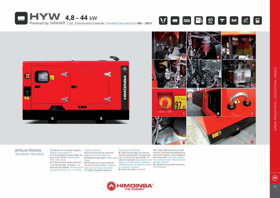
1. Radiador con ventilador soplante. Radiator with pusher fan.2. Filtro de gasóil con decantador de agua (nivel visible).Decanting fuel filter (visible level)3. Protecciones de partes calientes y móviles (escape, ventilador,...) y delantera del radiador. Mobile and hot protection (exhaust, fan...) and front
radiator protection.4. Kit de extracción de aceite del cárter. Oil sump extraction kit.5. Resistencia de caldeo. Water jacket heater.6. Alternador de carga de baterías con toma de tierra.Battery charging alternator with earth connection.7. Pulsador Parada Emergencia.
Emergency Push Button.8. Capot insonorizado, con lana de roca de alta densidad. Amplias puer-tas y controles de agua /aceite, en caso de necesidad. Sound attenuated canopy, with high density rockwool. Wide doors and manholes for water / oil, incase of necessity.9. Gancho de Izado.Lifting eye.
10. Chasis totalmente estanco que hace las funciones de bandeja de re-tención de líquidos. Incluye depósito de combustible. Fully tight chassis that works as liquids retention basin. Includes fuel tank.11. Cavidad para carretilla elevadora_Forklift pocket.
5
2 3
4
1
6
7 8 9
10 11
GA
MA
IND
UST
RIA
L | I
ND
UST
RIA
L R
AN
GE
Powered by: YANMAR | GE_Insonorizado Estándar | Standard Soundproof | 480 - 240 V4,8 - 44 kWHYW
DETALLES TÉCNICOSTECHNICAL FEATURES
29

Modelo G. E. | Genset Model HYW-6 T6 HYW-9 T6 HYW-14 T6 HYW-20 T6 HYW-25 T6 HYW-35 T6 HYW-35 T6 HYW-45 T6 HYW-45 T6
Modelo Motor_Engine Model 3TNM68 GHFCG 3TNV76 GGEH 3TNV88 BGGEH 4TNV88 BGGEH 4TNV84T BGGEH 4TNV98 GGEH 4TNV98 ZGGEH 4TNV98T GGEH 4TNV98T ZGGEH
R.P.M. 1.800 1.800 1.800 1.800 1.800 1.800 1.800 1.800 1.800
Potencia P.R.P._Power P.R.P. kVA / kW 6,5 / 5,2 9,9 / 7,9 15,2 / 12,2 21 / 16,5 26 / 21 40 / 32 40 / 32 50 / 40 50 / 40
Potencia Standby_Power Standby kVA / kW 7,1 / 5,7 10,7 / 8,6 16,6 / 13,3 23 / 18 28 / 23 44 / 36 44 / 36 55 / 44 55 / 44
Norma 97/68/EC TIER IV TIER IV TIER IV INT. TIER IV INT. TIER IV • INT. TIER IV • INT. TIER IV
Tensión de salida_Output voltage V 480 480 480 480 480 480 480 480 480
Factor potencia Cos phi_Power factor Cos phi 0,8 0,8 0,8 0,8 0,8 0,8 0,8 0,8 0,8
Cilindros_Cylindres Nº 3 - L 3 - L 3 - L 4 - L 4 - L 4 - L 4 - L 4 - L 4 - L
Aspiración (1)_Aspiration (1) NA NA NA NA TC NA NA TC TC
Regulador_Governor M M M M M M E M E
Versión constructiva_Constructive version K1 K1 K1 K1 K2 K3 K3 K3 K3
Dimensiones (mm)_Dimensions (mm) L x W x H 1450 x 620 x 1286 1450 x 620 x 1286 1450 x 620 x 1286 1450 x 620 x 1286 1700 x 620 x 1286 1850 x 780 x 1500 1850 x 780 x 1500 1850 x 780 x 1500 1850 x 780 x 1500
Peso_Weight Kg 307 307 362 397 416 545 545 626 626
Capacidad depósito_Fuel tank capacity L 60 60 60 60 76 120 120 120 120
Versión constructiva_Constructive version A10 A10 A10 B10 B10 B10 B10 B10 B10
Dimensiones (mm)_Dimensions (mm) L x W x H 1475 x 750 x 1110 1475 x 750 x 1110 1475 x 750 x 1110 2100 x 975 x 1349 2100 x 975 x 1349 2100 x 975 x 1349 2100 x 975 x 1349 2100 x 975 x 1349 2100 x 975 x 1349
Peso_Weight Kg 615 632 691 870 885 950 950 960 960
Capacidad depósito_Fuel tank capacity L 22 22 22 100 100 100 100 100 100
Nivel de ruido @ 7m_Noise level @ 7m dB(A) 61 66 61 59 59 64 64 64 64
*Dimensiones (mm)_Dimensions (mm) L x W x H N.A. N.A. N.A. 3417 x 1430 x 1710 3417 x 1430 x 1710 3417 x 1430 x 1710 3417 x 1430 x 1710 3417 x 1430 x 1710 3417 x 1430 x 1710
Peso_Weight Kg N.A. N.A. N.A. 1030 1045 1110 1110 1120 1120
(1) NA = Aspiración Natural / Natural Aspirated; TC = Turboalimentado / Turbocharged * Datos referidos a Kit móvil de desplazamiento lento (Kit móvil homologado consultar)* Data relating to Low speed trailers (Please consult for High speed trailers)
GA
MA
IND
UST
RIA
L | I
ND
UST
RIA
L R
AN
GE
DPowered by: YANMAR | DATOS TECNICOS | TECHNICAL DATA |
4,8 - 44 kWHYW
• No cumple con EPA 40 CFR Parte 89 / Not according to directive EPA 40 CFR Part 89
TIER II, TIER III, TIER IV, INT. TIER IVCumple con EPA 40 CFR Parte 89 / According to directive EPA 40 CFR Part 89
30
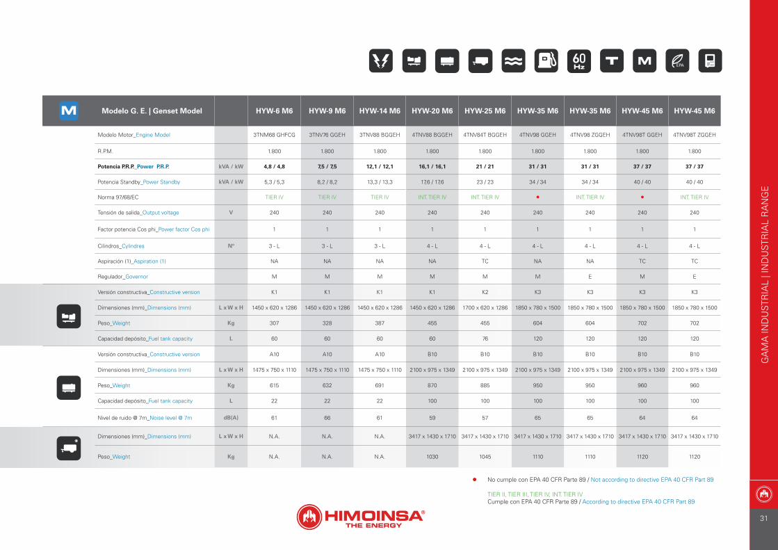
Modelo G. E. | Genset Model HYW-6 M6 HYW-9 M6 HYW-14 M6 HYW-20 M6 HYW-25 M6 HYW-35 M6 HYW-35 M6 HYW-45 M6 HYW-45 M6
Modelo Motor_Engine Model 3TNM68 GHFCG 3TNV76 GGEH 3TNV88 BGGEH 4TNV88 BGGEH 4TNV84T BGGEH 4TNV98 GGEH 4TNV98 ZGGEH 4TNV98T GGEH 4TNV98T ZGGEH
R.P.M. 1.800 1.800 1.800 1.800 1.800 1.800 1.800 1.800 1.800
Potencia P.R.P._Power P.R.P. kVA / kW 4,8 / 4,8 7,5 / 7,5 12,1 / 12,1 16,1 / 16,1 21 / 21 31 / 31 31 / 31 37 / 37 37 / 37
Potencia Standby_Power Standby kVA / kW 5,3 / 5,3 8,2 / 8,2 13,3 / 13,3 17,6 / 17,6 23 / 23 34 / 34 34 / 34 40 / 40 40 / 40
Norma 97/68/EC TIER IV TIER IV TIER IV INT. TIER IV INT. TIER IV • INT. TIER IV • INT. TIER IV
Tensión de salida_Output voltage V 240 240 240 240 240 240 240 240 240
Factor potencia Cos phi_Power factor Cos phi 1 1 1 1 1 1 1 1 1
Cilindros_Cylindres Nº 3 - L 3 - L 3 - L 4 - L 4 - L 4 - L 4 - L 4 - L 4 - L
Aspiración (1)_Aspiration (1) NA NA NA NA TC NA NA TC TC
Regulador_Governor M M M M M M E M E
Versión constructiva_Constructive version K1 K1 K1 K1 K2 K3 K3 K3 K3
Dimensiones (mm)_Dimensions (mm) L x W x H 1450 x 620 x 1286 1450 x 620 x 1286 1450 x 620 x 1286 1450 x 620 x 1286 1700 x 620 x 1286 1850 x 780 x 1500 1850 x 780 x 1500 1850 x 780 x 1500 1850 x 780 x 1500
Peso_Weight Kg 307 328 387 455 455 604 604 702 702
Capacidad depósito_Fuel tank capacity L 60 60 60 60 76 120 120 120 120
Versión constructiva_Constructive version A10 A10 A10 B10 B10 B10 B10 B10 B10
Dimensiones (mm)_Dimensions (mm) L x W x H 1475 x 750 x 1110 1475 x 750 x 1110 1475 x 750 x 1110 2100 x 975 x 1349 2100 x 975 x 1349 2100 x 975 x 1349 2100 x 975 x 1349 2100 x 975 x 1349 2100 x 975 x 1349
Peso_Weight Kg 615 632 691 870 885 950 950 960 960
Capacidad depósito_Fuel tank capacity L 22 22 22 100 100 100 100 100 100
Nivel de ruido @ 7m_Noise level @ 7m dB(A) 61 66 61 59 57 65 65 64 64
*Dimensiones (mm)_Dimensions (mm) L x W x H N.A. N.A. N.A. 3417 x 1430 x 1710 3417 x 1430 x 1710 3417 x 1430 x 1710 3417 x 1430 x 1710 3417 x 1430 x 1710 3417 x 1430 x 1710
Peso_Weight Kg N.A. N.A. N.A. 1030 1045 1110 1110 1120 1120
GA
MA
IND
UST
RIA
L | I
ND
UST
RIA
L R
AN
GE
• No cumple con EPA 40 CFR Parte 89 / Not according to directive EPA 40 CFR Part 89
TIER II, TIER III, TIER IV, INT. TIER IVCumple con EPA 40 CFR Parte 89 / According to directive EPA 40 CFR Part 89
31
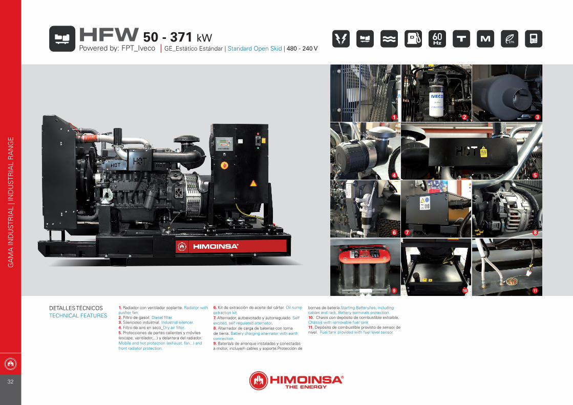
1. Radiador con ventilador soplante. Radiator with pusher fan.2. Filtro de gasoil. Diesel filter.3. Silencioso industrial. Industrial silencer.4. Filtro de aire en seco_Dry air filter.5. Protecciones de partes calientes y móviles (escape, ventilador,...) y delantera del radiador. Mobile and hot protection (exhaust, fan...) and front radiator protection.
6. Kit de extracción de aceite del cárter. Oil sump extraction kit.7. Alternador, autoexcitado y autorregulado. Self excited, self regulated alternator.8. Alternador de carga de baterías con toma de tierra. Battery charging alternator with earth connection.9. Batería/s de arranque instaladas y conectadas a motor, incluye/n cables y soporte.Protección de
bornas de batería.Starting Battery/ies, including cables and rack, Battery terminals protection.10. Chasis con depósito de combustible extraible. Chassis with removable fuel tank11. Depósito de combustible provisto de sensor de nivel. Fuel tank provided with fuel level sensor.
1
4 5
7
2
6 8
109 11
3
GA
MA
IND
UST
RIA
L | I
ND
UST
RIA
L R
AN
GE
Powered by: FPT_Iveco | GE_Estático Estándar | Standard Open Skid | 480 - 240 V50 - 371 kWHFW
DETALLES TÉCNICOSTECHNICAL FEATURES
32

1. Radiador con ventilador soplante. Radiator with pusher fan.2. Filtro de gasoil. Diesel filter.3. Sensor de nivel agua radiador_Low coolant level sensor.4. Filtro de aire en seco_Dry air filter.5. Protecciones de partes calientes y móviles (escape, ventilador,...) y delantera del radiador. Mobile and hot protection (exhaust, fan...) and
front radiator protection.6. Cuadro eléctrico de control y potencia, con aparatos de medida central de control (según necesidad y configuración) y protección magne-totérmica.Control and power electric panel, with measurements devices, controller (according to necessity and configuration) and thermal magnetic protection.7. Desconectador de batería/s (Opcional).Battery isolator (Optional).
8. Batería/s de arranque instaladas y conectadas a motor, incluye/n cables y soporte.Protección de bornas de batería.Starting Battery/ies, including cables and rack, Battery terminals protection.9. Gancho de Izado.Lifting eye.10. Capot insonorizado, con lana de roca de alta densidad. Amplias puertas y controles de agua /aceite, en caso de necesidad. Sound attenuated canopy, with high density rockwool. Wide doors and manholes for water / oil, incase of necessity.
1
2 3
4 5
10
7 8
96
GA
MA
IND
UST
RIA
L | I
ND
UST
RIA
L R
AN
GE
Powered by: FPT_Iveco | GE_Insonorizado Estándar | Standard Soundproof | 480 - 240 V50 - 371 kWHFW
DETALLES TÉCNICOSTECHNICAL FEATURES
33
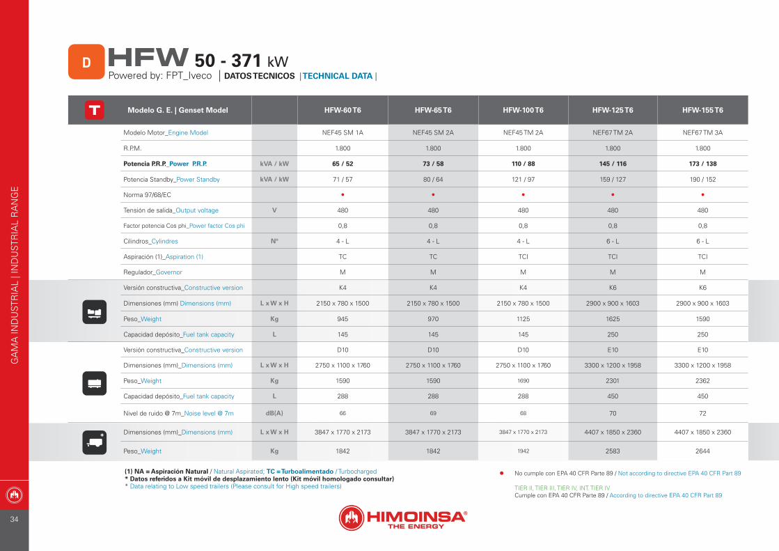
Modelo G. E. | Genset Model HFW-60 T6 HFW-65 T6 HFW-100 T6 HFW-125 T6 HFW-155 T6
Modelo Motor_Engine Model NEF45 SM 1A NEF45 SM 2A NEF45 TM 2A NEF67 TM 2A NEF67 TM 3A
R.P.M. 1.800 1.800 1.800 1.800 1.800
Potencia P.R.P._Power P.R.P. kVA / kW 65 / 52 73 / 58 110 / 88 145 / 116 173 / 138
Potencia Standby_Power Standby kVA / kW 71 / 57 80 / 64 121 / 97 159 / 127 190 / 152
Norma 97/68/EC • • • • •
Tensión de salida_Output voltage V 480 480 480 480 480
Factor potencia Cos phi_Power factor Cos phi 0,8 0,8 0,8 0,8 0,8
Cilindros_Cylindres Nº 4 - L 4 - L 4 - L 6 - L 6 - L
Aspiración (1)_Aspiration (1) TC TC TCI TCI TCI
Regulador_Governor M M M M M
Versión constructiva_Constructive version K4 K4 K4 K6 K6
Dimensiones (mm) Dimensions (mm) L x W x H 2150 x 780 x 1500 2150 x 780 x 1500 2150 x 780 x 1500 2900 x 900 x 1603 2900 x 900 x 1603
Peso_Weight Kg 945 970 1125 1625 1590
Capacidad depósito_Fuel tank capacity L 145 145 145 250 250
Versión constructiva_Constructive version D10 D10 D10 E10 E10
Dimensiones (mm)_Dimensions (mm) L x W x H 2750 x 1100 x 1760 2750 x 1100 x 1760 2750 x 1100 x 1760 3300 x 1200 x 1958 3300 x 1200 x 1958
Peso_Weight Kg 1590 1590 1690 2301 2362
Capacidad depósito_Fuel tank capacity L 288 288 288 450 450
Nivel de ruido @ 7m_Noise level @ 7m dB(A) 66 69 68 70 72
*Dimensiones (mm)_Dimensions (mm) L x W x H 3847 x 1770 x 2173 3847 x 1770 x 2173 3847 x 1770 x 2173 4407 x 1850 x 2360 4407 x 1850 x 2360
Peso_Weight Kg 1842 1842 1942 2583 2644
(1) NA = Aspiración Natural / Natural Aspirated; TC = Turboalimentado / Turbocharged * Datos referidos a Kit móvil de desplazamiento lento (Kit móvil homologado consultar)* Data relating to Low speed trailers (Please consult for High speed trailers)
GA
MA
IND
UST
RIA
L | I
ND
UST
RIA
L R
AN
GE
DPowered by: FPT_Iveco | DATOS TECNICOS | TECHNICAL DATA |
50 - 371 kWHFW
• No cumple con EPA 40 CFR Parte 89 / Not according to directive EPA 40 CFR Part 89
TIER II, TIER III, TIER IV, INT. TIER IVCumple con EPA 40 CFR Parte 89 / According to directive EPA 40 CFR Part 89
34
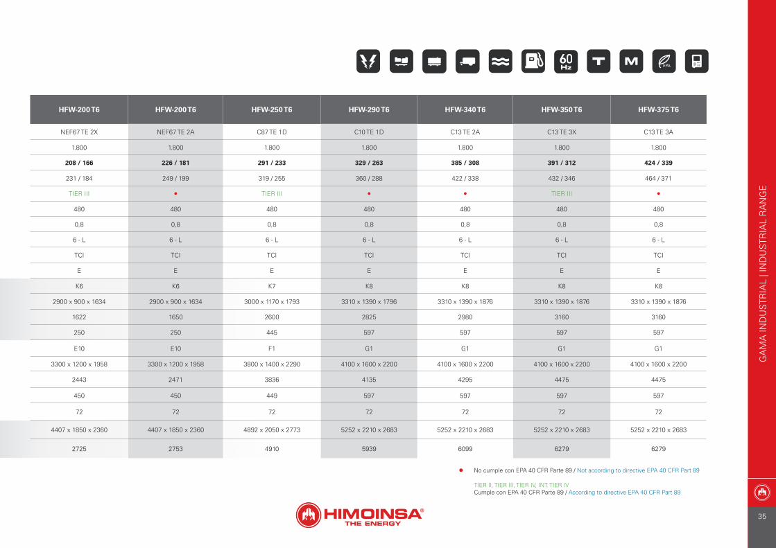
HFW-200 T6 HFW-200 T6 HFW-250 T6 HFW-290 T6 HFW-340 T6 HFW-350 T6 HFW-375 T6
NEF67 TE 2X NEF67 TE 2A C87 TE 1D C10 TE 1D C13 TE 2A C13 TE 3X C13 TE 3A
1.800 1.800 1.800 1.800 1.800 1.800 1.800
208 / 166 226 / 181 291 / 233 329 / 263 385 / 308 391 / 312 424 / 339
231 / 184 249 / 199 319 / 255 360 / 288 422 / 338 432 / 346 464 / 371
TIER III • TIER III • • TIER III •
480 480 480 480 480 480 480
0,8 0,8 0,8 0,8 0,8 0,8 0,8
6 - L 6 - L 6 - L 6 - L 6 - L 6 - L 6 - L
TCI TCI TCI TCI TCI TCI TCI
E E E E E E E
K6 K6 K7 K8 K8 K8 K8
2900 x 900 x 1634 2900 x 900 x 1634 3000 x 1170 x 1793 3310 x 1390 x 1796 3310 x 1390 x 1876 3310 x 1390 x 1876 3310 x 1390 x 1876
1622 1650 2600 2825 2980 3160 3160
250 250 445 597 597 597 597
E10 E10 F1 G1 G1 G1 G1
3300 x 1200 x 1958 3300 x 1200 x 1958 3800 x 1400 x 2290 4100 x 1600 x 2200 4100 x 1600 x 2200 4100 x 1600 x 2200 4100 x 1600 x 2200
2443 2471 3836 4135 4295 4475 4475
450 450 449 597 597 597 597
72 72 72 72 72 72 72
4407 x 1850 x 2360 4407 x 1850 x 2360 4892 x 2050 x 2773 5252 x 2210 x 2683 5252 x 2210 x 2683 5252 x 2210 x 2683 5252 x 2210 x 2683
2725 2753 4910 5939 6099 6279 6279
GA
MA
IND
UST
RIA
L | I
ND
UST
RIA
L R
AN
GE
• No cumple con EPA 40 CFR Parte 89 / Not according to directive EPA 40 CFR Part 89
TIER II, TIER III, TIER IV, INT. TIER IVCumple con EPA 40 CFR Parte 89 / According to directive EPA 40 CFR Part 89
35
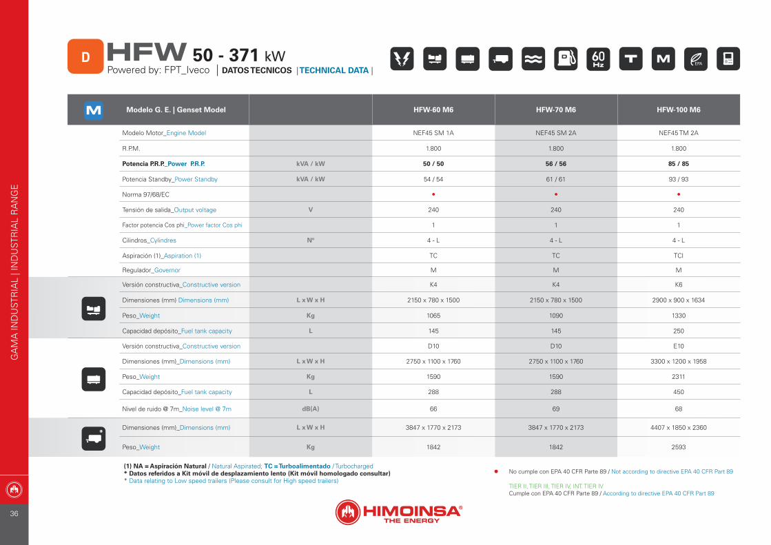
(1) NA = Aspiración Natural / Natural Aspirated; TC = Turboalimentado / Turbocharged * Datos referidos a Kit móvil de desplazamiento lento (Kit móvil homologado consultar)* Data relating to Low speed trailers (Please consult for High speed trailers)
Modelo G. E. | Genset Model HFW-60 M6 HFW-70 M6 HFW-100 M6
Modelo Motor_Engine Model NEF45 SM 1A NEF45 SM 2A NEF45 TM 2A
R.P.M. 1.800 1.800 1.800
Potencia P.R.P._Power P.R.P. kVA / kW 50 / 50 56 / 56 85 / 85
Potencia Standby_Power Standby kVA / kW 54 / 54 61 / 61 93 / 93
Norma 97/68/EC • • •
Tensión de salida_Output voltage V 240 240 240
Factor potencia Cos phi_Power factor Cos phi 1 1 1
Cilindros_Cylindres Nº 4 - L 4 - L 4 - L
Aspiración (1)_Aspiration (1) TC TC TCI
Regulador_Governor M M M
Versión constructiva_Constructive version K4 K4 K6
Dimensiones (mm) Dimensions (mm) L x W x H 2150 x 780 x 1500 2150 x 780 x 1500 2900 x 900 x 1634
Peso_Weight Kg 1065 1090 1330
Capacidad depósito_Fuel tank capacity L 145 145 250
Versión constructiva_Constructive version D10 D10 E10
Dimensiones (mm)_Dimensions (mm) L x W x H 2750 x 1100 x 1760 2750 x 1100 x 1760 3300 x 1200 x 1958
Peso_Weight Kg 1590 1590 2311
Capacidad depósito_Fuel tank capacity L 288 288 450
Nivel de ruido @ 7m_Noise level @ 7m dB(A) 66 69 68
*Dimensiones (mm)_Dimensions (mm) L x W x H 3847 x 1770 x 2173 3847 x 1770 x 2173 4407 x 1850 x 2360
Peso_Weight Kg 1842 1842 2593
GA
MA
IND
UST
RIA
L | I
ND
UST
RIA
L R
AN
GE
DPowered by: FPT_Iveco | DATOS TECNICOS | TECHNICAL DATA |
50 - 371 kWHFW
• No cumple con EPA 40 CFR Parte 89 / Not according to directive EPA 40 CFR Part 89
TIER II, TIER III, TIER IV, INT. TIER IVCumple con EPA 40 CFR Parte 89 / According to directive EPA 40 CFR Part 89
36
GA
MA
IND
UST
RIA
L | I
ND
UST
RIA
L R
AN
GE
37
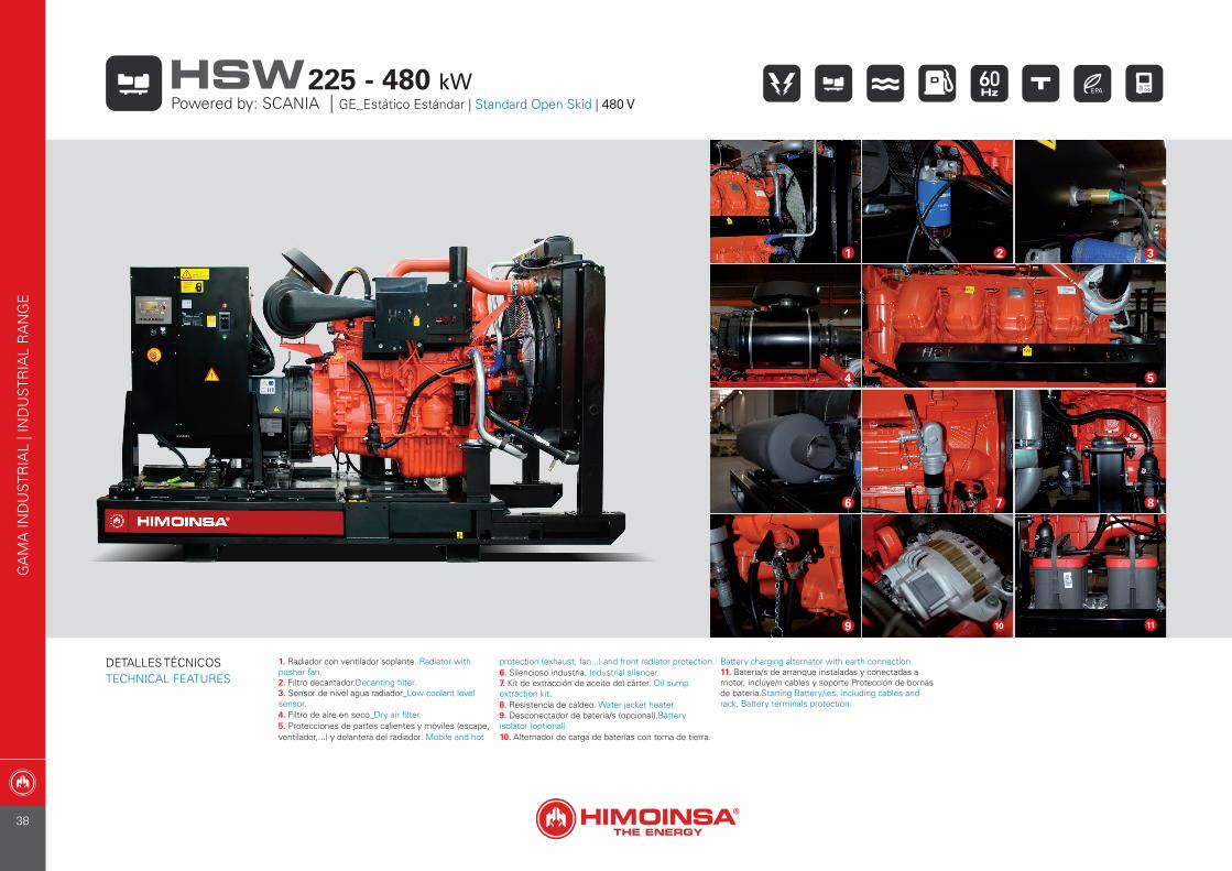
1. Radiador con ventilador soplante. Radiator with pusher fan.2. Filtro decantador.Decanting filter.3. Sensor de nivel agua radiador_Low coolant level sensor.4. Filtro de aire en seco_Dry air filter.5. Protecciones de partes calientes y móviles (escape, ventilador,...) y delantera del radiador. Mobile and hot
protection (exhaust, fan...) and front radiator protection.6. Silencioso industria. Industrial silencer.7. Kit de extracción de aceite del cárter. Oil sump extraction kit.8. Resistencia de caldeo. Water jacket heater.9. Desconectador de batería/s (opcional).Battery isolator (optional).10. Alternador de carga de baterías con toma de tierra.
Battery charging alternator with earth connection.11. Batería/s de arranque instaladas y conectadas a motor, incluye/n cables y soporte.Protección de bornas de batería.Starting Battery/ies, including cables and rack, Battery terminals protection.
11
2 3
4 5
6 7 8
1
9 10
GA
MA
IND
UST
RIA
L | I
ND
UST
RIA
L R
AN
GE
Powered by: SCANIA | GE_Estático Estándar | Standard Open Skid | 480 V225 - 480 kWHSW
DETALLES TÉCNICOSTECHNICAL FEATURES
38
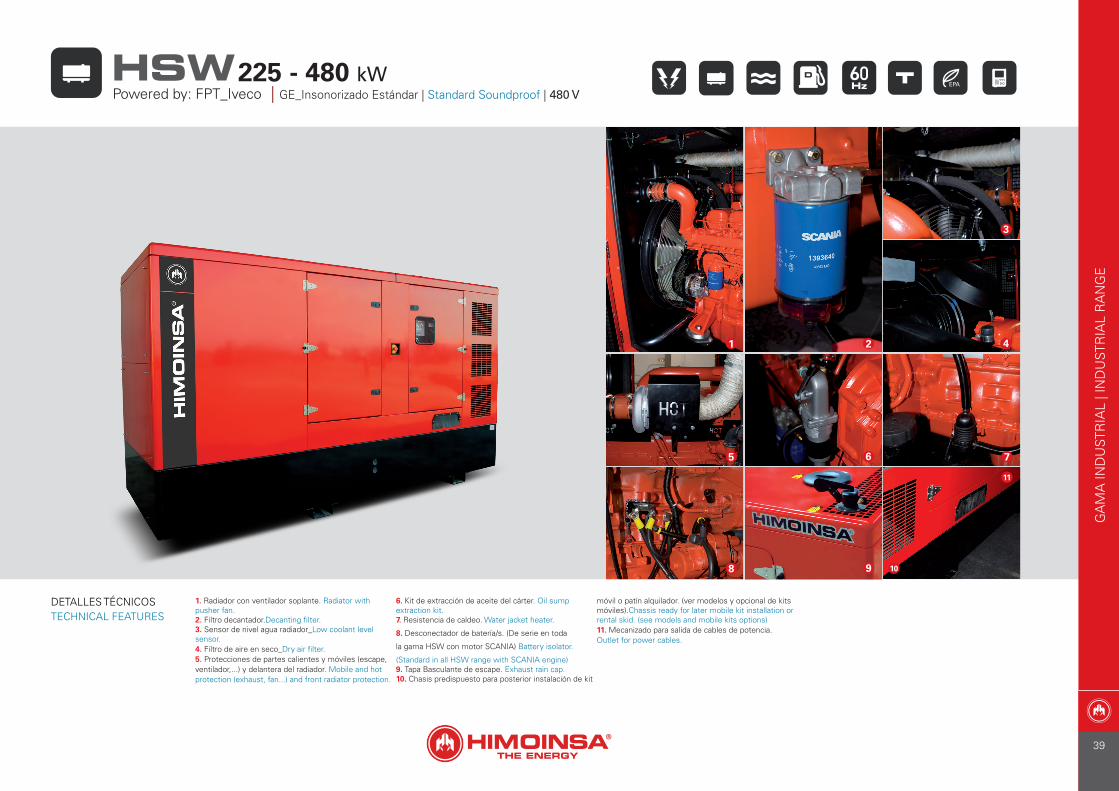
1. Radiador con ventilador soplante. Radiator with pusher fan.2. Filtro decantador.Decanting filter.3. Sensor de nivel agua radiador_Low coolant level sensor.4. Filtro de aire en seco_Dry air filter.5. Protecciones de partes calientes y móviles (escape, ventilador,...) y delantera del radiador. Mobile and hot protection (exhaust, fan...) and front radiator protection.
6. Kit de extracción de aceite del cárter. Oil sump extraction kit.7. Resistencia de caldeo. Water jacket heater.
8. Desconectador de batería/s. (De serie en toda
la gama HSW con motor SCANIA) Battery isolator.
(Standard in all HSW range with SCANIA engine)9. Tapa Basculante de escape. Exhaust rain cap.10. Chasis predispuesto para posterior instalación de kit
móvil o patín alquilador. (ver modelos y opcional de kits móviles).Chassis ready for later mobile kit installation or rental skid. (see models and mobile kits options)11. Mecanizado para salida de cables de potencia. Outlet for power cables.
9 10
42
6 7
1
8
3
11
5
GA
MA
IND
UST
RIA
L | I
ND
UST
RIA
L R
AN
GE
225 - 480 kWHSWPowered by: FPT_Iveco | GE_Insonorizado Estándar | Standard Soundproof | 480 V
DETALLES TÉCNICOSTECHNICAL FEATURES
39
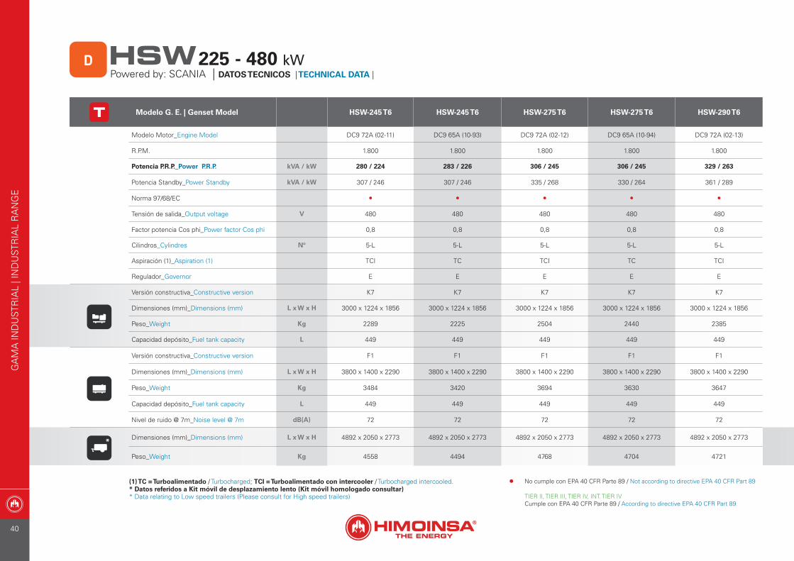
Modelo G. E. | Genset Model HSW-245 T6 HSW-245 T6 HSW-275 T6 HSW-275 T6 HSW-290 T6
Modelo Motor_Engine Model DC9 72A (02-11) DC9 65A (10-93) DC9 72A (02-12) DC9 65A (10-94) DC9 72A (02-13)
R.P.M. 1.800 1.800 1.800 1.800 1.800
Potencia P.R.P._Power P.R.P. kVA / kW 280 / 224 283 / 226 306 / 245 306 / 245 329 / 263
Potencia Standby_Power Standby kVA / kW 307 / 246 307 / 246 335 / 268 330 / 264 361 / 289
Norma 97/68/EC • • • • •
Tensión de salida_Output voltage V 480 480 480 480 480
Factor potencia Cos phi_Power factor Cos phi 0,8 0,8 0,8 0,8 0,8
Cilindros_Cylindres Nº 5-L 5-L 5-L 5-L 5-L
Aspiración (1)_Aspiration (1) TCI TC TCI TC TCI
Regulador_Governor E E E E E
Versión constructiva_Constructive version K7 K7 K7 K7 K7
Dimensiones (mm)_Dimensions (mm) L x W x H 3000 x 1224 x 1856 3000 x 1224 x 1856 3000 x 1224 x 1856 3000 x 1224 x 1856 3000 x 1224 x 1856
Peso_Weight Kg 2289 2225 2504 2440 2385
Capacidad depósito_Fuel tank capacity L 449 449 449 449 449
Versión constructiva_Constructive version F1 F1 F1 F1 F1
Dimensiones (mm)_Dimensions (mm) L x W x H 3800 x 1400 x 2290 3800 x 1400 x 2290 3800 x 1400 x 2290 3800 x 1400 x 2290 3800 x 1400 x 2290
Peso_Weight Kg 3484 3420 3694 3630 3647
Capacidad depósito_Fuel tank capacity L 449 449 449 449 449
Nivel de ruido @ 7m_Noise level @ 7m dB(A) 72 72 72 72 72
Dimensiones (mm)_Dimensions (mm) L x W x H 4892 x 2050 x 2773 4892 x 2050 x 2773 4892 x 2050 x 2773 4892 x 2050 x 2773 4892 x 2050 x 2773
Peso_Weight Kg 4558 4494 4768 4704 4721
(1) TC = Turboalimentado / Turbocharged; TCI = Turboalimentado con intercooler / Turbocharged intercooled.* Datos referidos a Kit móvil de desplazamiento lento (Kit móvil homologado consultar)* Data relating to Low speed trailers (Please consult for High speed trailers)
*
GA
MA
IND
UST
RIA
L | I
ND
UST
RIA
L R
AN
GE
Powered by: SCANIA | DATOS TECNICOS | TECHNICAL DATA | 225 - 480 kWHSWD
• No cumple con EPA 40 CFR Parte 89 / Not according to directive EPA 40 CFR Part 89
TIER II, TIER III, TIER IV, INT. TIER IVCumple con EPA 40 CFR Parte 89 / According to directive EPA 40 CFR Part 89
40
(1) TC = Turboalimentado / Turbocharged; TCI = Turboalimentado con intercooler / Turbocharged intercooled.* Datos referidos a Kit móvil de desplazamiento lento (Kit móvil homologado consultar)* Data relating to Low speed trailers (Please consult for High speed trailers)
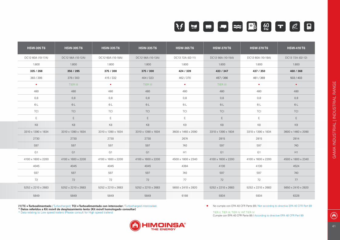
HSW-305 T6 HSW-305 T6 HSW-335 T6 HSW-335 T6 HSW-365 T6 HSW-370 T6 HSW-370 T6 HSW-410 T6
DC12 60A (10-17A) DC12 56A (10-12A) DC12 60A (10-18A) DC12 56A (10-13A) DC13 72A (02-11) DC12 56A (10-15A) DC12 60A (10-19A) DC13 72A (02-12)
1.800 1.800 1.800 1.800 1.800 1.800 1.800 1.800
335 / 268 356 / 285 375 / 300 375 / 300 424 / 339 433 / 347 437 / 350 460 / 368
383 / 306 378 / 303 415 / 332 404 / 323 462 / 370 457 / 366 461 / 369 503 / 403
• TIER III • TIER III • TIER III • •
480 480 480 480 480 480 480 480
0,8 0,8 0,8 0,8 0,8 0,8 0,8 0,8
6-L 6-L 6-L 6-L 6-L 6-L 6-L 6-L
TCI TCI TCI TCI TCI TCI TCI TCI
E E E E E E E E
K8 K8 K8 K8 K9 K8 K8 K9
3310 x 1390 x 1834 3310 x 1390 x 1834 3310 x 1390 x 1834 3310 x 1390 x 1834 3600 x 1460 x 2090 3310 x 1390 x 1834 3310 x 1390 x 1834 3600 x 1460 x 2090
2730 2730 2730 2730 2674 2815 2815 2814
597 597 597 597 740 597 597 740
G1 G1 G1 G1 H1 G1 G1 H1
4100 x 1600 x 2200 4100 x 1600 x 2200 4100 x 1600 x 2200 4100 x 1600 x 2200 4500 x 1800 x 2340 4100 x 1600 x 2200 4100 x 1600 x 2200 4500 x 1800 x 2340
4045 4045 4045 4045 4384 4130 4130 4524
597 597 597 597 740 597 597 740
72 72 72 72 77 72 72 77
5252 x 2210 x 2683 5252 x 2210 x 2683 5252 x 2210 x 2683 5252 x 2210 x 2683 5650 x 2410 x 2820 5252 x 2210 x 2683 5252 x 2210 x 2683 5650 x 2410 x 2820
5849 5849 5849 5849 6188 5934 5934 6328
GA
MA
IND
UST
RIA
L | I
ND
UST
RIA
L R
AN
GE
• No cumple con EPA 40 CFR Parte 89 / Not according to directive EPA 40 CFR Part 89
TIER II, TIER III, TIER IV, INT. TIER IVCumple con EPA 40 CFR Parte 89 / According to directive EPA 40 CFR Part 89
41

Modelo G. E. | Genset Model HSW-440 T6 HSW-440 T6 HSW-445 T6 HSW-480 T6
Modelo Motor_Engine Model DC16 43A (10-24A) DC16 45A (10-30A) DC13 72A (02-13) DC16 44A (10-27)
R.P.M. 1.800 1.800 1.800 1.800
Potencia P.R.P._Power P.R.P. kVA / kW 499 / 399 499 / 399 500 / 400 552 / 442
Potencia Standby_Power Standby kVA / kW 545 / 436 545 / 436 548 / 438 600 / 480
Norma 97/68/EC • TIER II • TIER II
Tensión de salida_Output voltage V 480 480 480 480
Factor potencia Cos phi_Power factor Cos phi 0,8 0,8 0,8 0,8
Cilindros_Cylindres Nº 90º V8 90º V8 6-L 90º V8
Aspiración (1)_Aspiration (1) TCI TCI TCI TCI
Regulador_Governor E E E E
Versión constructiva_Constructive version K9 K9 K9 K9
Dimensiones (mm)_Dimensions (mm) L x W x H 3600 x 1460 x 2090 3600 x 1460 x 2090 3600 x 1460 x 2090 3600 x 1460 x 2090
Peso_Weight Kg 3360 3360 3095 3330
Capacidad depósito_Fuel tank capacity L 740 740 740 740
Versión constructiva_Constructive version H1 H1 H1 H1
Dimensiones (mm)_Dimensions (mm) L x W x H 4500 x 1800 x 2340 4500 x 1800 x 2340 4500 x 1800 x 2340 4500 x 1800 x 2340
Peso_Weight Kg 5285 5285 5020 5388
Capacidad depósito_Fuel tank capacity L 740 740 740 740
Nivel de ruido @ 7m_Noise level @ 7m dB(A) 77 77 77 76
Dimensiones (mm)_Dimensions (mm) L x W x H 5650 x 2410 x 2820 5650 x 2410 x 2820 5650 x 2410 x 2820 5650 x 2410 x 2820
Peso_Weight Kg 7089 7089 6824 7192
(1) TC = Turboalimentado / Turbocharged; TCI = Turboalimentado con intercooler / Turbocharged intercooled.* Datos referidos a Kit móvil de desplazamiento lento (Kit móvil homologado consultar)* Data relating to Low speed trailers (Please consult for High speed trailers)
*
GA
MA
IND
UST
RIA
L | I
ND
UST
RIA
L R
AN
GE
Powered by: SCANIA | DATOS TECNICOS | TECHNICAL DATA | 225 - 480 kWHSWD
• No cumple con EPA 40 CFR Parte 89 / Not according to directive EPA 40 CFR Part 89
TIER II, TIER III, TIER IV, INT. TIER IVCumple con EPA 40 CFR Parte 89 / According to directive EPA 40 CFR Part 89
42

GA
MA
IND
UST
RIA
L | I
ND
UST
RIA
L R
AN
GE
43
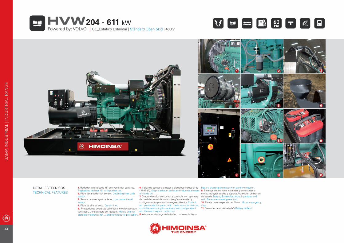
1. Radiador tropicalizado 45º con ventilador soplante.Tropicalized radiator 45º with pusher fan.2. Filtro decantador con sensor. Decanting filter with sensor.3. Sensor de nivel agua radiador. Low coolant level sensor.4. Filtro de aire en seco. Dry air filter.5. Protecciones de partes calientes y móviles (escape, ventilador,...) y delantera del radiador. Mobile and hot protection (exhaust, fan...) and front radiator protection.
6. Salida de escape de motor y silencioso industrial de -15 dB (A). Engine exhaust outlet and industrial silencer of -15 db (A).7. Cuadro eléctrico de control y potencia, con aparatos de medida central de control (según necesidad y configuración) y protección magnetotérmica.Control and power electric panel, with measurements devices, controller (according to necessity and configuration) and thermal magnetic protection.8. Alternador de carga de baterías con toma de tierra.
Battery charging alternator with earth connection.9. Batería/s de arranque instaladas y conectadas a motor, incluye/n cables y soporte.Protección de bornas de batería.Starting Battery/ies, including cables and rack, Battery terminals protection.10. Parada de emergencia del Motor. Motor emergency stop.11. Desconectador de batería/s.Battery isolator.
21 3
4 5 6
8 9
10 117
GA
MA
IND
UST
RIA
L | I
ND
UST
RIA
L R
AN
GE
Powered by: VOLVO | GE_Estático Estándar | Standard Open Skid | 480 V204 - 611 kWHVW
DETALLES TÉCNICOSTECHNICAL FEATURES
44
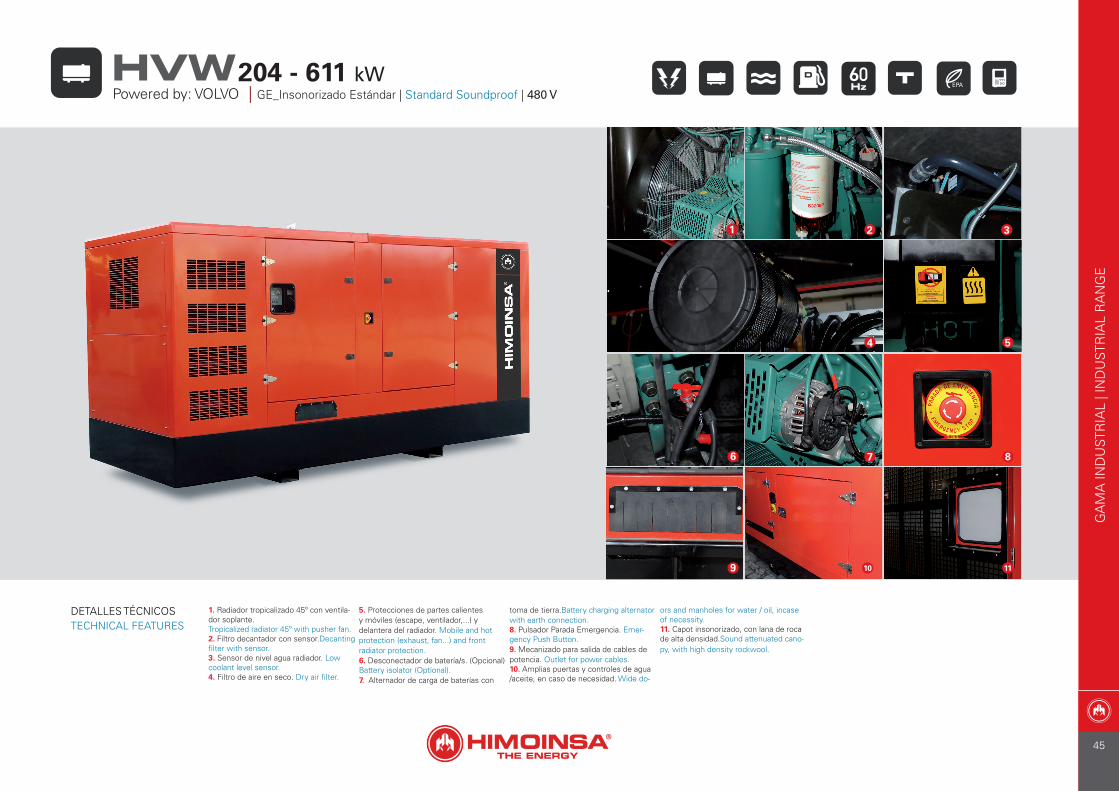
1. Radiador tropicalizado 45º con ventila-dor soplante.Tropicalized radiator 45º with pusher fan.2. Filtro decantador con sensor.Decanting filter with sensor.3. Sensor de nivel agua radiador. Low coolant level sensor.4. Filtro de aire en seco. Dry air filter.
5. Protecciones de partes calientes y móviles (escape, ventilador,...) y delantera del radiador. Mobile and hot protection (exhaust, fan...) and front radiator protection.6. Desconectador de batería/s. (Opcional) Battery isolator (Optional).7. Alternador de carga de baterías con
toma de tierra.Battery charging alternator with earth connection.8. Pulsador Parada Emergencia. Emer-gency Push Button.9. Mecanizado para salida de cables de potencia. Outlet for power cables.10. Amplias puertas y controles de agua /aceite, en caso de necesidad. Wide do-
ors and manholes for water / oil, incase of necessity. 11. Capot insonorizado, con lana de roca de alta densidad.Sound attenuated cano-py, with high density rockwool.
1 32
5
8
4
10
76
9 11
GA
MA
IND
UST
RIA
L | I
ND
UST
RIA
L R
AN
GE
204 - 611 kWHVWPowered by: VOLVO | GE_Insonorizado Estándar | Standard Soundproof | 480 V
DETALLES TÉCNICOSTECHNICAL FEATURES
45

Modelo G. E. | Genset Model HVW-225 T6 HVW-220 T6 HVW-250 T6 HVW-300 T6 HVW-305 T6
Modelo Motor_Engine Model TAD 734GE TAD 754GE TAD 1350GE TAD 941GE TAD 1351GE
R.P.M. 1.800 1.800 1.800 1.800 1.800
Potencia P.R.P._Power P.R.P. kVA / kW 255 / 204 255 / 204 284 / 227 336 / 269 343 / 274
Potencia Standby_Power Standby kVA / kW 280 / 224 280 / 224 311 / 249 370 / 296 375 / 300
Norma 97/68/EC • TIER III TIER III • TIER III
Tensión de salida_Output voltage V 480 480 480 480 480
Factor potencia Cos phi_Power factor Cos phi 0,8 0,8 0,8 0,8 0,8
Cilindros_Cylindres Nº 6 - L 6 - L 6 - L 6 - L 6 - L
Aspiración (1)_Aspiration (1) TCI TCI TCI TCI TCI
Regulador_Governor E E E E E
Versión constructiva_Constructive version K7 K7 K8 K8 K8
Dimensiones (mm)_Dimensions (mm) L x W x H 3000 x 1160 x 1776 3000 x 1160 x 1776 3310 x 1390 x 1832 3310 x 1390 x 1832 3310 x 1390 x 1832
Peso_Weight Kg 2313 2255 3125 2971 3338
Capacidad depósito_Fuel tank capacity L 445 445 597 597 597
Versión constructiva_Constructive version F1 F1 G1 G1 G1
Dimensiones (mm)_Dimensions (mm) L x W x H 3800 x 1400 x 2290 3800 x 1400 x 2290 4100 x 1600 x 2200 4100 x 1600 x 2200 4100 x 1600 x 2200
Peso_Weight Kg 3551 3493 4485 4331 4698
Capacidad depósito_Fuel tank capacity L 449 449 597 597 597
Nivel de ruido @ 7m_Noise level @ 7m dB(A) ConsultarTo be consulted
ConsultarTo be consulted
ConsultarTo be consulted
ConsultarTo be consulted NA
*Dimensiones (mm)_Dimensions (mm) L x W x H 4892 x 2050 x 2773 4892 x 2050 x 2773 5252 x 2210 x 2683 5252 x 2210 x 2683 5252 x 2210 x 2683
Peso_Weight Kg 4625 4567 6289 6135 6502
(1) TC = Turboalimentado / Turbocharged; TCI = Turboalimentado con intercooler / Turbocharged intercooled.* Datos referidos a Kit móvil de desplazamiento lento (Kit móvil homologado consultar)* Data relating to Low speed trailers (Please consult for High speed trailers)
GA
MA
IND
UST
RIA
L | I
ND
UST
RIA
L R
AN
GE
Powered by: VOLVO | DATOS TECNICOS | TECHNICAL DATA | 204 - 611 kWHVWD
• No cumple con EPA 40 CFR Parte 89 / Not according to directive EPA 40 CFR Part 89
TIER II, TIER III, TIER IV, INT. TIER IVCumple con EPA 40 CFR Parte 89 / According to directive EPA 40 CFR Part 89
46

(1) TC = Turboalimentado / Turbocharged; TCI = Turboalimentado con intercooler / Turbocharged intercooled.* Datos referidos a Kit móvil de desplazamiento lento (Kit móvil homologado consultar)* Data relating to Low speed trailers (Please consult for High speed trailers)
GA
MA
IND
UST
RIA
L | I
ND
UST
RIA
L R
AN
GE
HVW-355 T6 HVW-400 T6 HVW-440 T6 HVW-440 T6 HVW-515 T6 HVW-515 T6 HVW-555 T6 HVW-615 T6
TAD 1352GE TAD 1353GE TAD 1640GE TAD 1650GE TAD 1641GE TAD 1651GE TAD 1642GE TWD 1643GE
1.800 1.800 1.800 1.800 1.800 1.800 1.800 1.800
403 / 322 458 / 366 500 / 400 500 / 400 576 / 461 587 / 469 632 / 505 695 / 556
439 / 351 501 / 401 550 / 440 550 / 440 647 / 518 647 / 518 693 / 555 764 / 611
TIER III TIER III • TIER III • TIER II • TIER II
480 480 480 480 480 480 480 480
0,8 0,8 0,8 0,8 0,8 0,8 0,8 0,8
6 - L 6 - L 6 - L 6 - L 6 - L 6 - L 6 - L 6 - L
TCI TCI TCI TCI TCI TCI TCI TCI
E E E E E E E E
K8 K8 K9 K9 K9 K9 K9 K18
3310 x 1390 x 1880 3310 x 1390 x 1880 3600 x 1460 x 2114 3600 x 1460 x 2114 3600 x 1460 x 2114 3600 x 1460 x 2114 3600 x 1460 x 2114 4170 x 1600 x 2237
3509 3645 4033 4198 4133 4298 4343 4835
597 597 740 740 740 740 740 880
G1 G1 H1 H1 H1 H1 H1 J
4100 x 1600 x 2200 4100 x 1600 x 2200 4500 x 1800 x 2340 4500 x 1800 x 2340 4500 x 1800 x 2340 4500 x 1800 x 2340 4500 x 1800 x 2340 5000 x 2100 x 2294
4869 5005 6013 6178 6113 6278 6323 6370
597 597 740 740 740 740 740 950
NA NA NA NA NA NA NA NA
5252 x 2210 x 2683 5252 x 2210 x 2683 5650 x 2410 x 2820 5650 x 2410 x 2820 5650 x 2410 x 2820 5650 x 2410 x 2820 5650 x 2410 x 2820 N.A.
6673 6809 7817 7982 7917 8082 8127 N.A.
• No cumple con EPA 40 CFR Parte 89 / Not according to directive EPA 40 CFR Part 89
TIER II, TIER III, TIER IV, INT. TIER IVCumple con EPA 40 CFR Parte 89 / According to directive EPA 40 CFR Part 89
47
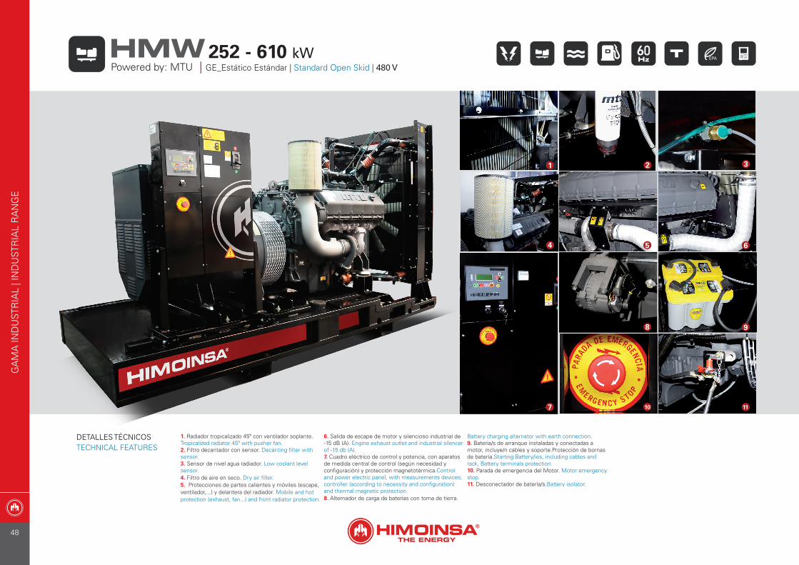
1. Radiador tropicalizado 45º con ventilador soplante.Tropicalized radiator 45º with pusher fan.2. Filtro decantador con sensor. Decanting filter with sensor.3. Sensor de nivel agua radiador. Low coolant level sensor.4. Filtro de aire en seco. Dry air filter.5. Protecciones de partes calientes y móviles (escape, ventilador,...) y delantera del radiador. Mobile and hot protection (exhaust, fan...) and front radiator protection.
6. Salida de escape de motor y silencioso industrial de -15 dB (A). Engine exhaust outlet and industrial silencer of -15 db (A).7. Cuadro eléctrico de control y potencia, con aparatos de medida central de control (según necesidad y configuración) y protección magnetotérmica.Control and power electric panel, with measurements devices, controller (according to necessity and configuration) and thermal magnetic protection.8. Alternador de carga de baterías con toma de tierra.
Battery charging alternator with earth connection.9. Batería/s de arranque instaladas y conectadas a motor, incluye/n cables y soporte.Protección de bornas de batería.Starting Battery/ies, including cables and rack, Battery terminals protection.10. Parada de emergencia del Motor. Motor emergency stop.11. Desconectador de batería/s.Battery isolator.
4 5 6
8 9
10 117
GA
MA
IND
UST
RIA
L | I
ND
UST
RIA
L R
AN
GE
Powered by: MTU | GE_Estático Estándar | Standard Open Skid | 480 V252 - 610 kWHMW
DETALLES TÉCNICOSTECHNICAL FEATURES
21 3
48
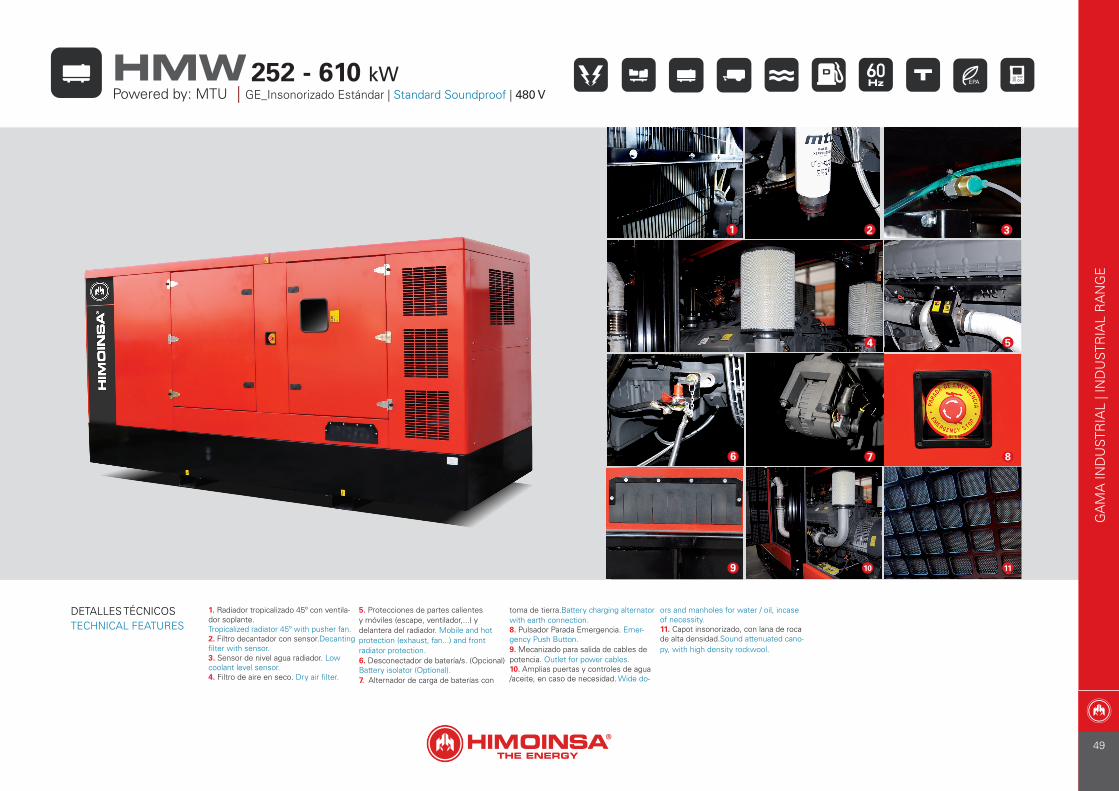
1. Radiador tropicalizado 45º con ventila-dor soplante.Tropicalized radiator 45º with pusher fan.2. Filtro decantador con sensor.Decanting filter with sensor.3. Sensor de nivel agua radiador. Low coolant level sensor.4. Filtro de aire en seco. Dry air filter.
5. Protecciones de partes calientes y móviles (escape, ventilador,...) y delantera del radiador. Mobile and hot protection (exhaust, fan...) and front radiator protection.6. Desconectador de batería/s. (Opcional) Battery isolator (Optional).7. Alternador de carga de baterías con
toma de tierra.Battery charging alternator with earth connection.8. Pulsador Parada Emergencia. Emer-gency Push Button.9. Mecanizado para salida de cables de potencia. Outlet for power cables.10. Amplias puertas y controles de agua /aceite, en caso de necesidad. Wide do-
ors and manholes for water / oil, incase of necessity. 11. Capot insonorizado, con lana de roca de alta densidad.Sound attenuated cano-py, with high density rockwool.
32
5
8
4
10
76
9 11
GA
MA
IND
UST
RIA
L | I
ND
UST
RIA
L R
AN
GE
252 - 610 kWHMWPowered by: MTU | GE_Insonorizado Estándar | Standard Soundproof | 480 V
DETALLES TÉCNICOSTECHNICAL FEATURES
1
49
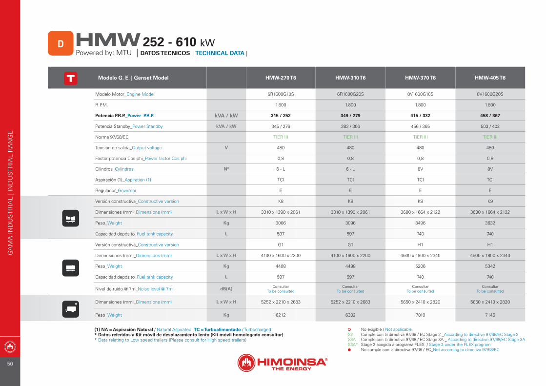
Modelo G. E. | Genset Model HMW-270 T6 HMW-310 T6 HMW-370 T6 HMW-405 T6
Modelo Motor_Engine Model 6R1600G10S 6R1600G20S 8V1600G10S 8V1600G20S
R.P.M. 1.800 1.800 1.800 1.800
Potencia P.R.P._Power P.R.P. kVA / kW 315 / 252 349 / 279 415 / 332 458 / 367
Potencia Standby_Power Standby kVA / kW 345 / 276 383 / 306 456 / 365 503 / 402
Norma 97/68/EC TIER III TIER III TIER III TIER III
Tensión de salida_Output voltage V 480 480 480 480
Factor potencia Cos phi_Power factor Cos phi 0,8 0,8 0,8 0,8
Cilindros_Cylindres Nº 6 - L 6 - L 8V 8V
Aspiración (1)_Aspiration (1) TCI TCI TCI TCI
Regulador_Governor E E E E
Versión constructiva_Constructive version K8 K8 K9 K9
Dimensiones (mm)_Dimensions (mm) L x W x H 3310 x 1390 x 2061 3310 x 1390 x 2061 3600 x 1664 x 2122 3600 x 1664 x 2122
Peso_Weight Kg 3006 3096 3496 3632
Capacidad depósito_Fuel tank capacity L 597 597 740 740
Versión constructiva_Constructive version G1 G1 H1 H1
Dimensiones (mm)_Dimensions (mm) L x W x H 4100 x 1600 x 2200 4100 x 1600 x 2200 4500 x 1800 x 2340 4500 x 1800 x 2340
Peso_Weight Kg 4408 4498 5206 5342
Capacidad depósito_Fuel tank capacity L 597 597 740 740
Nivel de ruido @ 7m_Noise level @ 7m dB(A) ConsultarTo be consulted
ConsultarTo be consulted
ConsultarTo be consulted
ConsultarTo be consulted
* Dimensiones (mm)_Dimensions (mm) L x W x H 5252 x 2210 x 2683 5252 x 2210 x 2683 5650 x 2410 x 2820 5650 x 2410 x 2820
Peso_Weight Kg 6212 6302 7010 7146
(1) NA = Aspiración Natural / Natural Aspirated; TC = Turboalimentado / Turbocharged * Datos referidos a Kit móvil de desplazamiento lento (Kit móvil homologado consultar)* Data relating to Low speed trailers (Please consult for High speed trailers)
S2S3AS3A*
No exigible / Not applicableCumple con la directiva 97/68 / EC Stage 2 _According to directive 97/68/EC Stage 2Cumple con la directiva 97/68 / EC Stage 3A _ According to directive 97/68/EC Stage 3AStage 2 acogido a programa FLEX / Stage 2 under the FLEX programNo cumple con la directiva 97/68 / EC_Not according to directive 97/68/EC
GA
MA
IND
UST
RIA
L | I
ND
UST
RIA
L R
AN
GE
Powered by: MTU | DATOS TECNICOS | TECHNICAL DATA | D 252 - 610 kWHMW
50
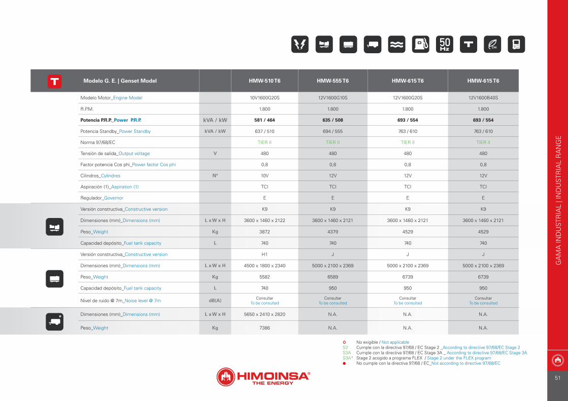
Modelo G. E. | Genset Model HMW-510 T6 HMW-555 T6 HMW-615 T6 HMW-615 T6
Modelo Motor_Engine Model 10V1600G20S 12V1600G10S 12V1600G20S 12V1600B40S
R.P.M. 1.800 1.800 1.800 1.800
Potencia P.R.P._Power P.R.P. kVA / kW 581 / 464 635 / 508 693 / 554 693 / 554
Potencia Standby_Power Standby kVA / kW 637 / 510 694 / 555 763 / 610 763 / 610
Norma 97/68/EC TIER II TIER II TIER II TIER II
Tensión de salida_Output voltage V 480 480 480 480
Factor potencia Cos phi_Power factor Cos phi 0,8 0,8 0,8 0,8
Cilindros_Cylindres Nº 10V 12V 12V 12V
Aspiración (1)_Aspiration (1) TCI TCI TCI TCI
Regulador_Governor E E E E
Versión constructiva_Constructive version K9 K9 K9 K9
Dimensiones (mm)_Dimensions (mm) L x W x H 3600 x 1460 x 2122 3600 x 1460 x 2121 3600 x 1460 x 2121 3600 x 1460 x 2121
Peso_Weight Kg 3872 4379 4529 4529
Capacidad depósito_Fuel tank capacity L 740 740 740 740
Versión constructiva_Constructive version H1 J J J
Dimensiones (mm)_Dimensions (mm) L x W x H 4500 x 1800 x 2340 5000 x 2100 x 2369 5000 x 2100 x 2369 5000 x 2100 x 2369
Peso_Weight Kg 5582 6589 6739 6739
Capacidad depósito_Fuel tank capacity L 740 950 950 950
Nivel de ruido @ 7m_Noise level @ 7m dB(A) ConsultarTo be consulted
ConsultarTo be consulted
ConsultarTo be consulted
ConsultarTo be consulted
* Dimensiones (mm)_Dimensions (mm) L x W x H 5650 x 2410 x 2820 N.A. N.A. N.A.
Peso_Weight Kg 7386 N.A. N.A. N.A.
S2S3AS3A*
No exigible / Not applicableCumple con la directiva 97/68 / EC Stage 2 _According to directive 97/68/EC Stage 2Cumple con la directiva 97/68 / EC Stage 3A _ According to directive 97/68/EC Stage 3AStage 2 acogido a programa FLEX / Stage 2 under the FLEX programNo cumple con la directiva 97/68 / EC_Not according to directive 97/68/EC
GA
MA
IND
UST
RIA
L | I
ND
UST
RIA
L R
AN
GE
51
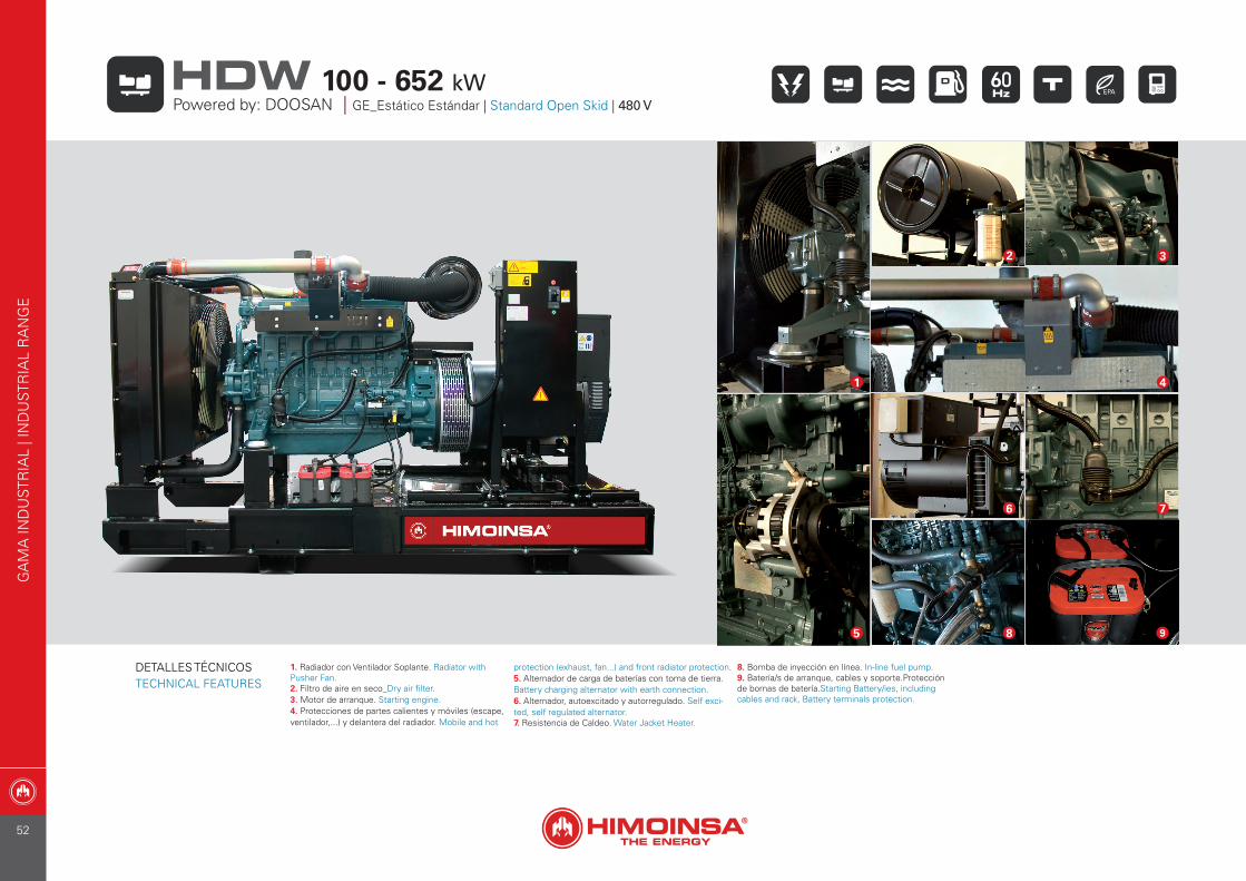
1. Radiador con Ventilador Soplante. Radiator with Pusher Fan.2. Filtro de aire en seco_Dry air filter.3. Motor de arranque. Starting engine.4. Protecciones de partes calientes y móviles (escape, ventilador,...) y delantera del radiador. Mobile and hot
protection (exhaust, fan...) and front radiator protection.5. Alternador de carga de baterías con toma de tierra.Battery charging alternator with earth connection.6. Alternador, autoexcitado y autorregulado. Self exci-ted, self regulated alternator.7. Resistencia de Caldeo. Water Jacket Heater.
8. Bomba de inyección en línea. In-line fuel pump.9. Batería/s de arranque, cables y soporte.Protección de bornas de batería.Starting Battery/ies, including cables and rack, Battery terminals protection.
1
2
7
4
3
9
6
85
GA
MA
IND
UST
RIA
L | I
ND
UST
RIA
L R
AN
GE
Powered by: DOOSAN | GE_Estático Estándar | Standard Open Skid | 480 V100 - 652 kWHDW
DETALLES TÉCNICOSTECHNICAL FEATURES
52
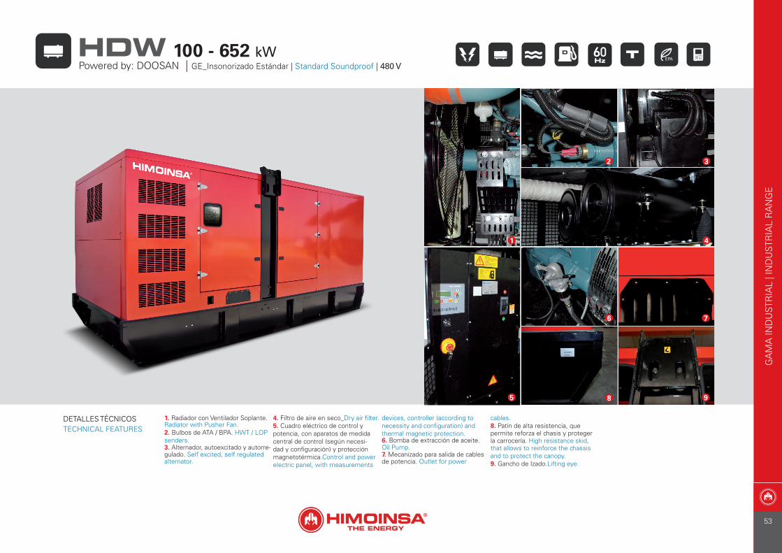
1. Radiador con Ventilador Soplante. Radiator with Pusher Fan.2. Bulbos de ATA / BPA. HWT / LOP senders.3. Alternador, autoexcitado y autorre-gulado. Self excited, self regulated alternator.
4. Filtro de aire en seco_Dry air filter.5. Cuadro eléctrico de control y potencia, con aparatos de medida central de control (según necesi-dad y configuración) y protección magnetotérmica.Control and power electric panel, with measurements
devices, controller (according to necessity and configuration) and thermal magnetic protection.6. Bomba de extracción de aceite. Oil Pump.7. Mecanizado para salida de cables de potencia. Outlet for power
cables.8. Patín de alta resistencia, que permite reforza el chasis y proteger la carrocería. High resistance skid, that allows to reinforce the chassis and to protect the canopy.9. Gancho de Izado.Lifting eye.
8 9
7
1
2
4
6
5
3
GA
MA
IND
UST
RIA
L | I
ND
UST
RIA
L R
AN
GE
100 - 652 kWHDWPowered by: DOOSAN | GE_Insonorizado Estándar | Standard Soundproof | 480 V
DETALLES TÉCNICOSTECHNICAL FEATURES
53
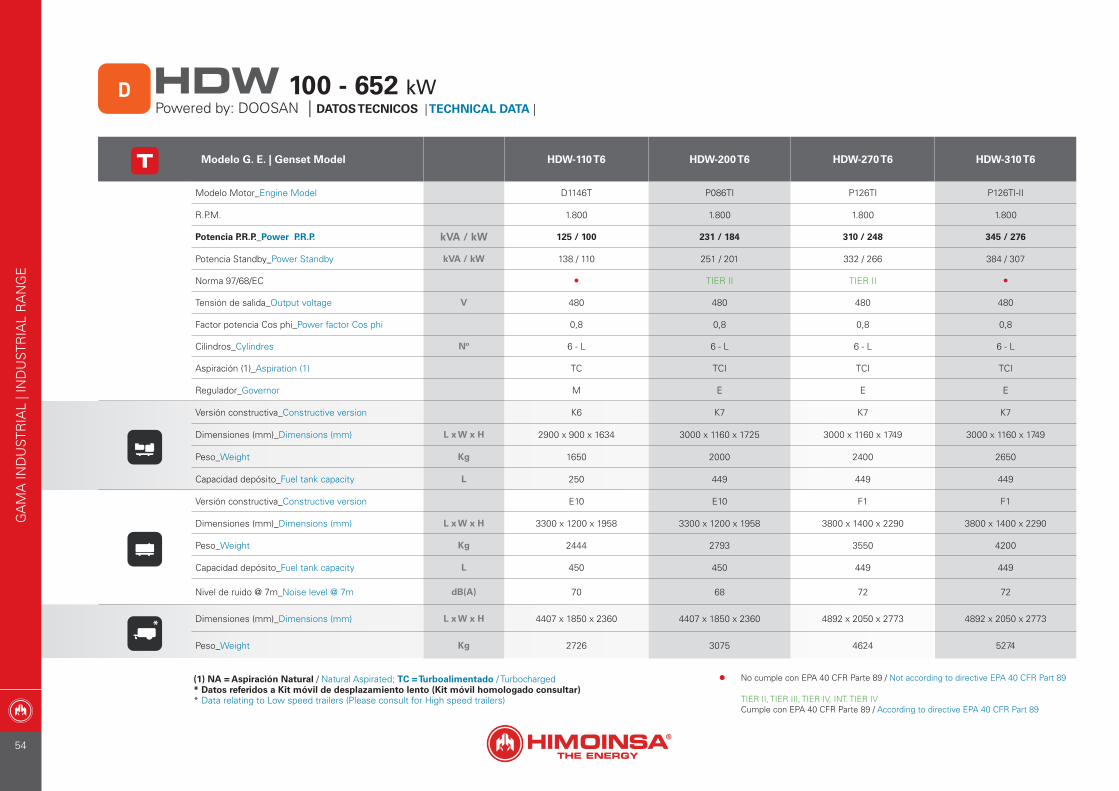
Modelo G. E. | Genset Model HDW-110 T6 HDW-200 T6 HDW-270 T6 HDW-310 T6
Modelo Motor_Engine Model D1146T P086TI P126TI P126TI-II
R.P.M. 1.800 1.800 1.800 1.800
Potencia P.R.P._Power P.R.P. kVA / kW 125 / 100 231 / 184 310 / 248 345 / 276
Potencia Standby_Power Standby kVA / kW 138 / 110 251 / 201 332 / 266 384 / 307
Norma 97/68/EC • TIER II TIER II •
Tensión de salida_Output voltage V 480 480 480 480
Factor potencia Cos phi_Power factor Cos phi 0,8 0,8 0,8 0,8
Cilindros_Cylindres Nº 6 - L 6 - L 6 - L 6 - L
Aspiración (1)_Aspiration (1) TC TCI TCI TCI
Regulador_Governor M E E E
Versión constructiva_Constructive version K6 K7 K7 K7
Dimensiones (mm)_Dimensions (mm) L x W x H 2900 x 900 x 1634 3000 x 1160 x 1725 3000 x 1160 x 1749 3000 x 1160 x 1749
Peso_Weight Kg 1650 2000 2400 2650
Capacidad depósito_Fuel tank capacity L 250 449 449 449
Versión constructiva_Constructive version E10 E10 F1 F1
Dimensiones (mm)_Dimensions (mm) L x W x H 3300 x 1200 x 1958 3300 x 1200 x 1958 3800 x 1400 x 2290 3800 x 1400 x 2290
Peso_Weight Kg 2444 2793 3550 4200
Capacidad depósito_Fuel tank capacity L 450 450 449 449
Nivel de ruido @ 7m_Noise level @ 7m dB(A) 70 68 72 72
* Dimensiones (mm)_Dimensions (mm) L x W x H 4407 x 1850 x 2360 4407 x 1850 x 2360 4892 x 2050 x 2773 4892 x 2050 x 2773
Peso_Weight Kg 2726 3075 4624 5274
(1) NA = Aspiración Natural / Natural Aspirated; TC = Turboalimentado / Turbocharged * Datos referidos a Kit móvil de desplazamiento lento (Kit móvil homologado consultar)* Data relating to Low speed trailers (Please consult for High speed trailers)
GA
MA
IND
UST
RIA
L | I
ND
UST
RIA
L R
AN
GE
Powered by: DOOSAN | DATOS TECNICOS | TECHNICAL DATA | D 100 - 652 kWHDW
• No cumple con EPA 40 CFR Parte 89 / Not according to directive EPA 40 CFR Part 89
TIER II, TIER III, TIER IV, INT. TIER IVCumple con EPA 40 CFR Parte 89 / According to directive EPA 40 CFR Part 89
54
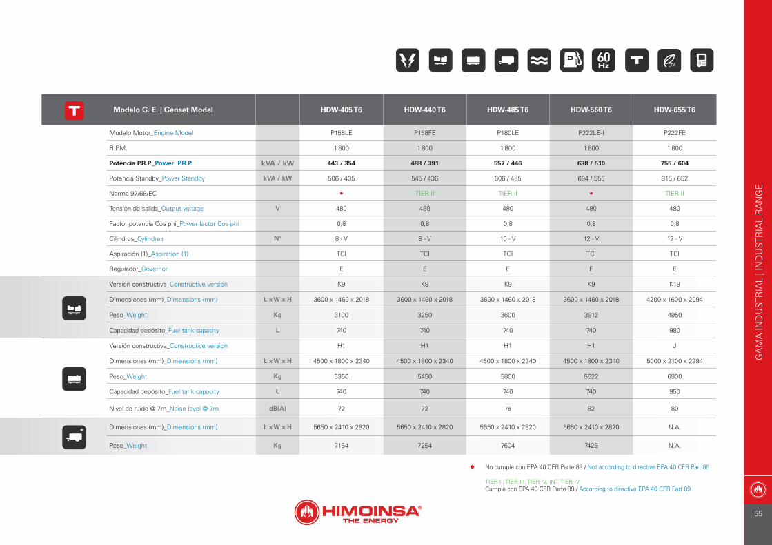
Modelo G. E. | Genset Model HDW-405 T6 HDW-440 T6 HDW-485 T6 HDW-560 T6 HDW-655 T6
Modelo Motor_Engine Model P158LE P158FE P180LE P222LE-I P222FE
R.P.M. 1.800 1.800 1.800 1.800 1.800
Potencia P.R.P._Power P.R.P. kVA / kW 443 / 354 488 / 391 557 / 446 638 / 510 755 / 604
Potencia Standby_Power Standby kVA / kW 506 / 405 545 / 436 606 / 485 694 / 555 815 / 652
Norma 97/68/EC • TIER II TIER II • TIER II
Tensión de salida_Output voltage V 480 480 480 480 480
Factor potencia Cos phi_Power factor Cos phi 0,8 0,8 0,8 0,8 0,8
Cilindros_Cylindres Nº 8 - V 8 - V 10 - V 12 - V 12 - V
Aspiración (1)_Aspiration (1) TCI TCI TCI TCI TCI
Regulador_Governor E E E E E
Versión constructiva_Constructive version K9 K9 K9 K9 K19
Dimensiones (mm)_Dimensions (mm) L x W x H 3600 x 1460 x 2018 3600 x 1460 x 2018 3600 x 1460 x 2018 3600 x 1460 x 2018 4200 x 1600 x 2094
Peso_Weight Kg 3100 3250 3600 3912 4950
Capacidad depósito_Fuel tank capacity L 740 740 740 740 980
Versión constructiva_Constructive version H1 H1 H1 H1 J
Dimensiones (mm)_Dimensions (mm) L x W x H 4500 x 1800 x 2340 4500 x 1800 x 2340 4500 x 1800 x 2340 4500 x 1800 x 2340 5000 x 2100 x 2294
Peso_Weight Kg 5350 5450 5800 5622 6900
Capacidad depósito_Fuel tank capacity L 740 740 740 740 950
Nivel de ruido @ 7m_Noise level @ 7m dB(A) 72 72 78 82 80
* Dimensiones (mm)_Dimensions (mm) L x W x H 5650 x 2410 x 2820 5650 x 2410 x 2820 5650 x 2410 x 2820 5650 x 2410 x 2820 N.A.
Peso_Weight Kg 7154 7254 7604 7426 N.A.
GA
MA
IND
UST
RIA
L | I
ND
UST
RIA
L R
AN
GE
• No cumple con EPA 40 CFR Parte 89 / Not according to directive EPA 40 CFR Part 89
TIER II, TIER III, TIER IV, INT. TIER IVCumple con EPA 40 CFR Parte 89 / According to directive EPA 40 CFR Part 89
55
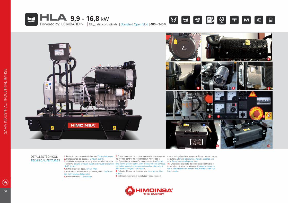
1. Protector de correa de ditribución. Timing belt cover.2. Protecciones del escape. Exhaust guards.3. Salida de escape de motor y silencioso industrial de -15 dB (A). Engine exhaust outlet and industrial silencer of -15 db (A).4. Filtro de aire en seco. Dry ail filter.5. Alternador, autoexcitado y autorregulado. Self exci-ted, self regulated alternator.6. Filtro de Gasoil. Diesel Filter.
7. Cuadro eléctrico de control y potencia, con aparatos de medida central de control (según necesidad y configuración) y protección magnetotérmica.Control and power electric panel, with measurements devices, controller (according to necessity and configuration) and thermal magnetic protection.8. Pulsador Parada de Emergencia. Emergency Stop Button.9. Batería/s de arranque instaladas y conectadas a
motor, incluye/n cables y soporte.Protección de bornas de batería.Starting Battery/ies, including cables and rack, Battery terminals protection.10. Chasis con depósito de combustible extraible e integrado y provisto de aforador. Chassis with remo-vable and integrated fuel tank and provided with fuel level sender.
7
11
1
3
6
10
7 8
9
2
54
GA
MA
IND
UST
RIA
L | I
ND
UST
RIA
L R
AN
GE
Powered by: LOMBARDINI | GE_Estático Estándar | Standard Open Skid | 480 - 240 V9,9 - 16,8 kWHLA
DETALLES TÉCNICOSTECHNICAL FEATURES
56
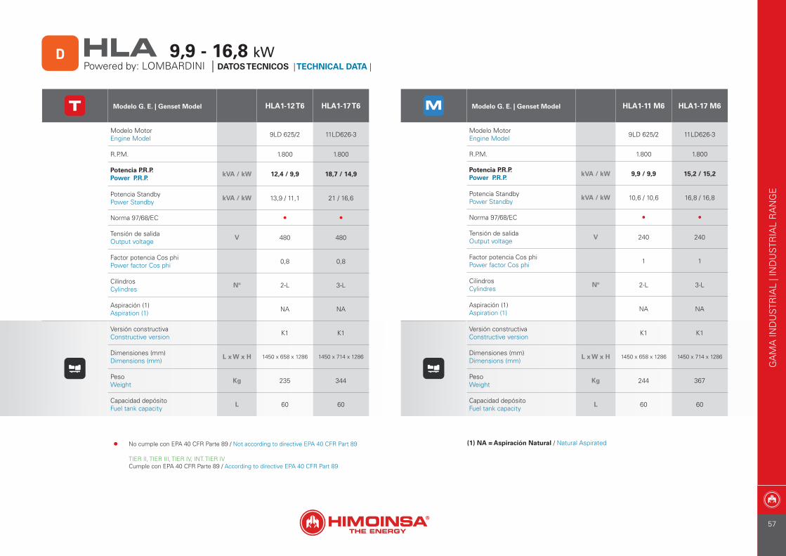
D
Modelo G. E. | Genset Model HLA1-12 T6 HLA1-17 T6
Modelo Motor Engine Model 9LD 625/2 11LD626-3
R.P.M. 1.800 1.800
Potencia P.R.P. Power P.R.P.
kVA / kW 12,4 / 9,9 18,7 / 14,9
Potencia StandbyPower Standby
kVA / kW 13,9 / 11,1 21 / 16,6
Norma 97/68/EC • •
Tensión de salidaOutput voltage
V 480 480
Factor potencia Cos phiPower factor Cos phi 0,8 0,8
CilindrosCylindres
Nº 2-L 3-L
Aspiración (1)Aspiration (1) NA NA
Versión constructivaConstructive version K1 K1
Dimensiones (mm) Dimensions (mm)
L x W x H 1450 x 658 x 1286 1450 x 714 x 1286
PesoWeight
Kg 235 344
Capacidad depósitoFuel tank capacity
L 60 60
Modelo G. E. | Genset Model HLA1-11 M6 HLA1-17 M6
Modelo Motor Engine Model 9LD 625/2 11LD626-3
R.P.M. 1.800 1.800
Potencia P.R.P. Power P.R.P.
kVA / kW 9,9 / 9,9 15,2 / 15,2
Potencia StandbyPower Standby
kVA / kW 10,6 / 10,6 16,8 / 16,8
Norma 97/68/EC • •
Tensión de salidaOutput voltage
V 240 240
Factor potencia Cos phiPower factor Cos phi 1 1
CilindrosCylindres
Nº 2-L 3-L
Aspiración (1)Aspiration (1) NA NA
Versión constructivaConstructive version K1 K1
Dimensiones (mm) Dimensions (mm)
L x W x H 1450 x 658 x 1286 1450 x 714 x 1286
PesoWeight
Kg 244 367
Capacidad depósitoFuel tank capacity
L 60 60
(1) NA = Aspiración Natural / Natural Aspirated
Powered by: LOMBARDINI | DATOS TECNICOS | TECHNICAL DATA | 9,9 - 16,8 kWHLA
GA
MA
IND
UST
RIA
L | I
ND
UST
RIA
L R
AN
GE
• No cumple con EPA 40 CFR Parte 89 / Not according to directive EPA 40 CFR Part 89
TIER II, TIER III, TIER IV, INT. TIER IVCumple con EPA 40 CFR Parte 89 / According to directive EPA 40 CFR Part 89
57

1. Protector de correa de ditribución. Timing belt cover.2. Protecciones del escape. Exhaust guards.3. Salida de escape de motor y silen-cioso industrial de -15 dB (A). Engine exhaust outlet and industrial silencer of -15 db (A).4. Filtro de aire en seco (INTERIOR). Dry air filter (INTERNAL).
5. Filtro de aire en seco (EXTERIOR). Dry air filter (OUTSIDE).6. Varilla y filtro de aceite. Oil filter and oil dip stick.7. Alternador, autoexcitado y autorre-gulado. Self excited, self regulated alternator.8. Cuadro eléctrico de control y potencia, con aparatos de medida central de control (según necesidad
y configuración) y protección magne-totérmica.Control and power electric panel, with measurements devices, controller (according to necessity and configuration) and thermal magnetic protection.9. Pulsador Parada de Emergencia. Emergency Stop Button.10. Batería/s de arranque instaladas y conectadas a motor, incluye/n cables
y soporte.Protección de bornas de batería.Starting Battery/ies, including cables and rack, Battery terminals protection.11. Chasis con depósito de combusti-ble extraible e integrado. Chassis with removable and integrated fuel tank.12. Aforador de combustible. Fuel tank provided with fuel level sender.
1
2
3
4
6
5
98
12
7
10 11
GA
MA
IND
UST
RIA
L | I
ND
UST
RIA
L R
AN
GE
Powered by: HATZ | GE_Estático Estándar | Standard Open Skid | 480 - 240 V
15,3 - 35 kWHZA
DETALLES TÉCNICOSTECHNICAL FEATURES
58
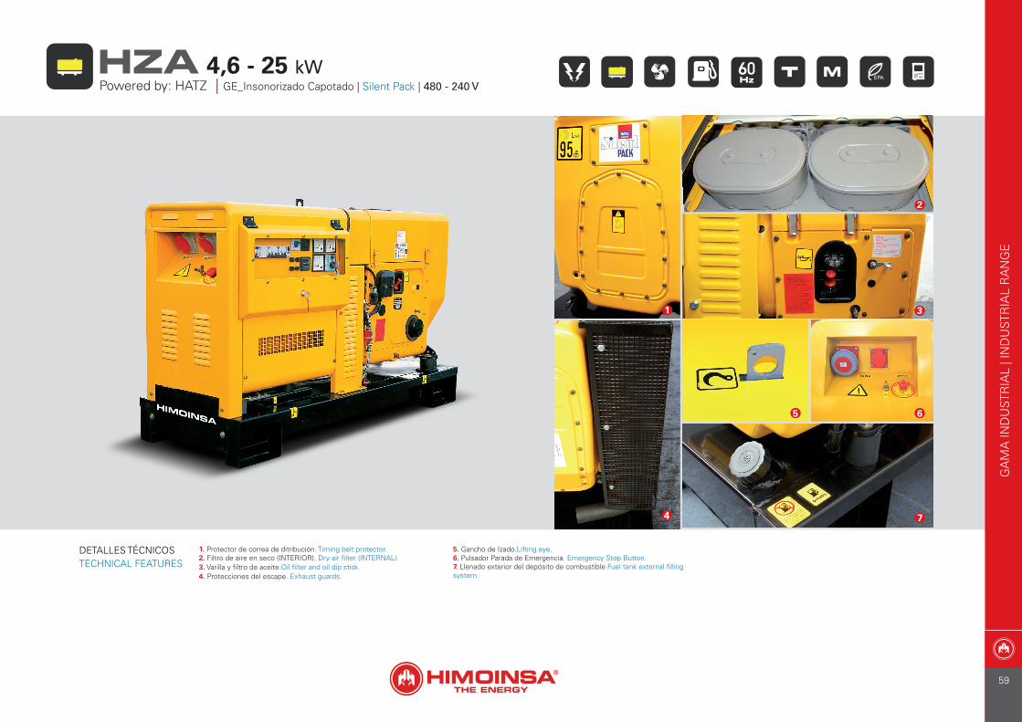
1. Protector de correa de ditribución. Timing belt protector.2. Filtro de aire en seco (INTERIOR). Dry air filter (INTERNAL).3. Varilla y filtro de aceite.Oil filter and oil dip stick.4. Protecciones del escape. Exhaust guards.
5. Gancho de Izado.Lifting eye.6. Pulsador Parada de Emergencia. Emergency Stop Button.7. Llenado exterior del depósito de combustible.Fuel tank external filling system.
1
4
2
3
7
5 6
GA
MA
IND
UST
RIA
L | I
ND
UST
RIA
L R
AN
GE
Powered by: HATZ | GE_Insonorizado Capotado | Silent Pack | 480 - 240 V
4,6 - 25 kWHZA
DETALLES TÉCNICOSTECHNICAL FEATURES
59
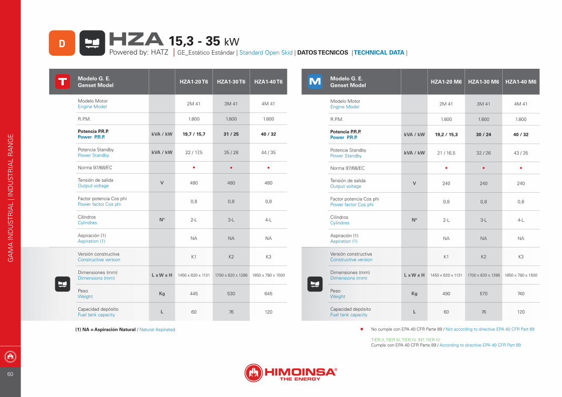
(1) NA = Aspiración Natural / Natural Aspirated
Modelo G. E. Genset Model
HZA1-20 T6 HZA1-30 T6 HZA1-40 T6
Modelo Motor Engine Model 2M 41 3M 41 4M 41
R.P.M. 1.800 1.800 1.800
Potencia P.R.P. Power P.R.P.
kVA / kW 19,7 / 15,7 31 / 25 40 / 32
Potencia StandbyPower Standby
kVA / kW 22 / 17,5 35 / 28 44 / 35
Norma 97/68/EC • • •
Tensión de salidaOutput voltage
V 480 480 480
Factor potencia Cos phiPower factor Cos phi 0,8 0,8 0,8
CilindrosCylindres
Nº 2-L 3-L 4-L
Aspiración (1)Aspiration (1) NA NA NA
Versión constructivaConstructive version K1 K2 K3
Dimensiones (mm) Dimensions (mm)
L x W x H 1450 x 620 x 1131 1700 x 620 x 1286 1850 x 780 x 1500
PesoWeight
Kg 445 530 645
Capacidad depósitoFuel tank capacity
L 60 76 120
Modelo G. E. Genset Model
HZA1-20 M6 HZA1-30 M6 HZA1-40 M6
Modelo Motor Engine Model 2M 41 3M 41 4M 41
R.P.M. 1.800 1.800 1.800
Potencia P.R.P. Power P.R.P.
kVA / kW 19,2 / 15,3 30 / 24 40 / 32
Potencia StandbyPower Standby
kVA / kW 21 / 16,5 32 / 26 43 / 35
Norma 97/68/EC • • •
Tensión de salidaOutput voltage
V 240 240 240
Factor potencia Cos phiPower factor Cos phi 0,8 0,8 0,8
CilindrosCylindres
Nº 2-L 3-L 4-L
Aspiración (1)Aspiration (1) NA NA NA
Versión constructivaConstructive version K1 K2 K3
Dimensiones (mm) Dimensions (mm)
L x W x H 1450 x 620 x 1131 1700 x 620 x 1286 1850 x 780 x 1500
PesoWeight
Kg 490 570 740
Capacidad depósitoFuel tank capacity
L 60 76 120
GA
MA
IND
UST
RIA
L | I
ND
UST
RIA
L R
AN
GE
Powered by: HATZ | GE_Estático Estándar | Standard Open Skid | DATOS TECNICOS | TECHNICAL DATA |
15,3 - 35 kWHZAD
• No cumple con EPA 40 CFR Parte 89 / Not according to directive EPA 40 CFR Part 89
TIER II, TIER III, TIER IV, INT. TIER IVCumple con EPA 40 CFR Parte 89 / According to directive EPA 40 CFR Part 89
60
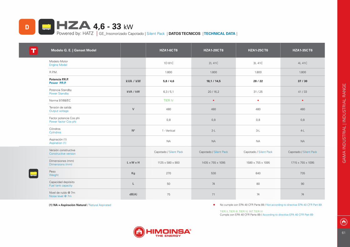
Modelo G. E. | Genset Model HZA1-6C T6 HZA1-20C T6 HZA1-25C T6 HZA1-35C T6
Modelo Motor Engine Model 1D 81C 2L 41C 3L 41C 4L 41C
R.P.M. 1.800 1.800 1.800 1.800
Potencia P.R.P. Power P.R.P. kVA / kW 5,8 / 4,6 18,1 / 14,5 28 / 22 37 / 30
Potencia StandbyPower Standby
kVA / kW 6,3 / 5,1 20 / 16,2 31 / 25 41 / 33
Norma 97/68/EC TIER IV • • •
Tensión de salidaOutput voltage
V 480 480 480 480
Factor potencia Cos phiPower factor Cos phi 0,8 0,8 0,8 0,8
CilindrosCylindres
Nº 1 - Vertical 2-L 3-L 4-L
Aspiración (1)Aspiration (1) NA NA NA NA
Versión constructivaConstructive version Capotado / Silent Pack Capotado / Silent Pack Capotado / Silent Pack Capotado / Silent Pack
Dimensiones (mm) Dimensions (mm)
L x W x H 1125 x 580 x 900 1435 x 755 x 1095 1580 x 755 x 1095 1715 x 755 x 1095
PesoWeight
Kg 270 530 640 735
Capacidad depósitoFuel tank capacity
L 50 74 80 90
Nivel de ruido @ 7mNoise level @ 7m
dB(A) 75 71 74 74
(1) NA = Aspiración Natural / Natural Aspirated
GA
MA
IND
UST
RIA
L | I
ND
UST
RIA
L R
AN
GE
Powered by: HATZ | GE_Insonorizado Capotado | Silent Pack | DATOS TECNICOS | TECHNICAL DATA |
4,6 - 33 kWHZAD
• No cumple con EPA 40 CFR Parte 89 / Not according to directive EPA 40 CFR Part 89
TIER II, TIER III, TIER IV, INT. TIER IVCumple con EPA 40 CFR Parte 89 / According to directive EPA 40 CFR Part 89
61
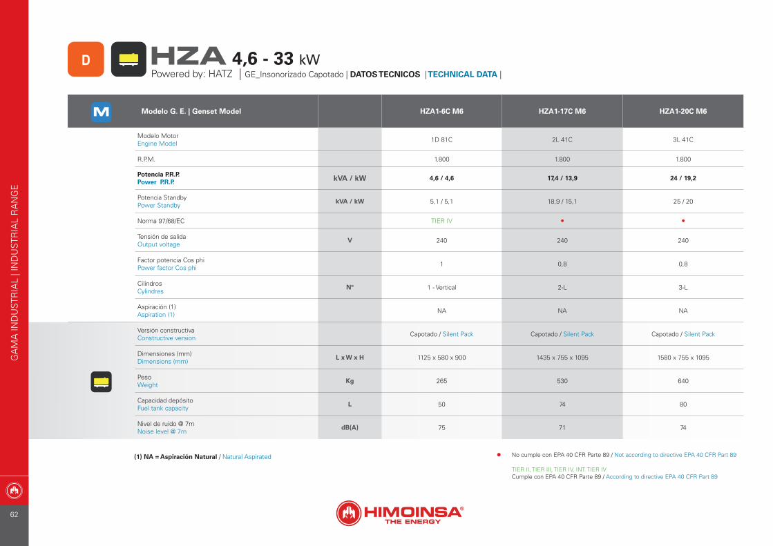
Modelo G. E. | Genset Model HZA1-6C M6 HZA1-17C M6 HZA1-20C M6
Modelo Motor Engine Model 1D 81C 2L 41C 3L 41C
R.P.M. 1.800 1.800 1.800
Potencia P.R.P. Power P.R.P. kVA / kW 4,6 / 4,6 17,4 / 13,9 24 / 19,2
Potencia StandbyPower Standby
kVA / kW 5,1 / 5,1 18,9 / 15,1 25 / 20
Norma 97/68/EC TIER IV • •
Tensión de salidaOutput voltage
V 240 240 240
Factor potencia Cos phiPower factor Cos phi 1 0,8 0,8
CilindrosCylindres
Nº 1 - Vertical 2-L 3-L
Aspiración (1)Aspiration (1) NA NA NA
Versión constructivaConstructive version Capotado / Silent Pack Capotado / Silent Pack Capotado / Silent Pack
Dimensiones (mm) Dimensions (mm)
L x W x H 1125 x 580 x 900 1435 x 755 x 1095 1580 x 755 x 1095
PesoWeight
Kg 265 530 640
Capacidad depósitoFuel tank capacity
L 50 74 80
Nivel de ruido @ 7mNoise level @ 7m
dB(A) 75 71 74
(1) NA = Aspiración Natural / Natural Aspirated
GA
MA
IND
UST
RIA
L | I
ND
UST
RIA
L R
AN
GE
Powered by: HATZ | GE_Insonorizado Capotado | DATOS TECNICOS | TECHNICAL DATA |
4,6 - 33 kWHZAD
• No cumple con EPA 40 CFR Parte 89 / Not according to directive EPA 40 CFR Part 89
TIER II, TIER III, TIER IV, INT. TIER IVCumple con EPA 40 CFR Parte 89 / According to directive EPA 40 CFR Part 89
62

GA
MA
RE
NTA
L |
RE
NTA
L R
AN
GE
APLICACIONES_APPLICATIONS:
Sector del Alquiler_Rental SectorCondiciones de Trabajo Extremas_Extreme Working Conditions
Obras Públicas_Public Building SitesConstrucción_Construction
Industrial Services_Servicios Industriales
SERIES: Powered by: YANMAR
Powered by: FPT (Iveco)
Powered by: SCANIA
Powered by: VOLVO
Powered by: DOOSAN
Powered by: MTU
Powered by: MITSUBISHI
HRYWHRFWHRSWHRVWHRDWHRMW
HRTW1300D 5-6DUAL-FREQUENCY
GAMA RENTALRENTAL RANGE
63
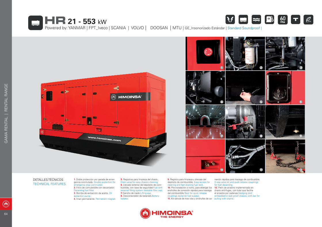
1. Doble protección por parada de emer-gencia conmutada. Double protection for emergency stop commuted.2. Filtro de comubstible con decantador.Decanting fuel filter.3. Bomba de extracción de aceite. Oil extraction pump.4. Iman permanente. Permanent magnet.
5. Registros para limpieza del chasis.Drain valve for easy chassis cleaning.6. Llenado exterior del depósito de com-bustible, con llave de seguridad.Fuel tank external filling system (lockable filler cap).7. Gancho de Izado.Lifting eye.8. Desconectador de batería/s.Battery isolator.
9. Registro para limpieza y drenaje del depósito de combustible. Easy access for cleaning and fast draining fuel tank.10. Pre-instalación o nicho, para albergar los enchufes de conexión rápidos para trasiego del combustible.Nest for quick release couplings (external fuel supply).11. Kit valvula de tres vías y enchufes de co-
nexión rápidos para trasiego de combustible. 3 way valve kit and quick release couptings for fuel decanting.12. Patín de arrastre implementado en chasis anti-fugas, con tubo que facilita el arrastre por cadenas.Sledging skid embedded in leak proof chassis, with bar for pulling with chains.
1 2 3
4 5 6
7 8 9
10 11 12
GA
MA
RE
NTA
L |
RE
NTA
L R
AN
GE
Powered by: YANMAR | FPT_Iveco | SCANIA | VOLVO | DOOSAN | MTU | GE_Insonorizado Estándar | Standard Soundproof |
21 - 553 kWHR
DETALLES TÉCNICOSTECHNICAL FEATURES
64
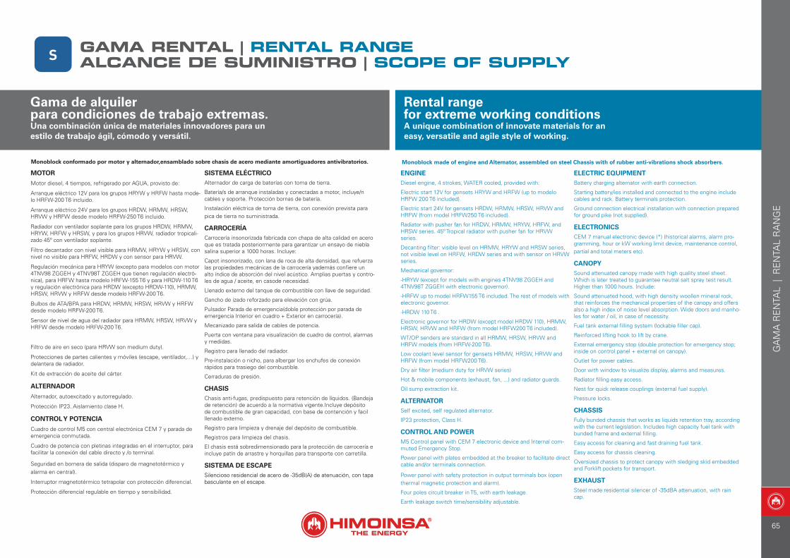
Monoblock conformado por motor y alternador,ensamblado sobre chasis de acero mediante amortiguadores antivibratorios.
MOTOR
Motor diesel, 4 tiempos, refrigerado por AGUA, provisto de:
Arranque eléctrico 12V para los grupos HRYW y HRFW hasta mode-lo HRFW-200 T6 incluido.
Arranque eléctrico 24V para los grupos HRDW, HRMW, HRSW, HRVW y HRFW desde modelo HRFW-250 T6 incluido.
Radiador con ventilador soplante para los grupos HRDW, HRMW, HRYW, HRFW y HRSW, y para los grupos HRVW, radiador tropicali-zado 45º con ventilador soplante.
Filtro decantador con nivel visible para HRMW, HRYW y HRSW, con nivel no visible para HRFW, HRDW y con sensor para HRVW.
Regulación mecánica para HRYW (excepto para modelos con motor 4TNV98 ZGGEH y 4TNV98T ZGGEH que tienen regulación electró-nica), para HRFW hasta modelo HRFW-155 T6 y para HRDW-110 T6 y regulación electrónica para HRDW (excepto HRDW-110), HRMW, HRSW, HRVW y HRFW desde modelo HRFW-200 T6.
Bulbos de ATA/BPA para HRDW, HRMW, HRSW, HRVW y HRFW desde modelo HRFW-200 T6.
Sensor de nivel de agua del radiador para HRMW, HRSW, HRVW y HRFW desde modelo HRFW-200 T6.
Filtro de aire en seco (para HRVW son medium duty).
Protecciones de partes calientes y móviles (escape, ventilador,…) y delantera de radiador.
Kit de extracción de aceite del cárter.
ALTERNADOR
Alternador, autoexcitado y autorregulado.
Protección IP23. Aislamiento clase H.
CONTROL Y POTENCIA
Cuadro de control M5 con central electrónica CEM 7 y parada de emergencia conmutada.
Cuadro de potencia con pletinas integradas en el interruptor, para facilitar la conexión del cable directo y /o terminal.
Seguridad en bornera de salida (disparo de magnetotérmico y alarma en central).
Interruptor magnetotérmico tetrapolar con protección diferencial.
Protección diferencial regulable en tiempo y sensibilidad.
SISTEMA ELÉCTRICOAlternador de carga de baterías con toma de tierra.
Batería/s de arranque instaladas y conectadas a motor, incluye/n cables y soporte. Protección bornas de batería.
Instalación eléctrica de toma de tierra, con conexión prevista para pica de tierra no suministrada.
CARROCERÍACarrocería insonorizada fabricada con chapa de alta calidad en acero que es tratada posteriormente para garantizar un ensayo de niebla salina superior a 1000 horas. Incluye:
Capot insonorizado, con lana de roca de alta densidad, que refuerza las propiedades mecánicas de la carrocería yademás confiere un alto índice de absorción del nivel acústico. Amplias puertas y contro-les de agua / aceite, en casode necesidad.
Llenado externo del tanque de combustible con llave de seguridad.
Gancho de izado reforzado para elevación con grúa.
Pulsador Parada de emergencia(doble protección por parada de emergencia Interior en cuadro + Exterior en carrocería).
Mecanizado para salida de cables de potencia.
Puerta con ventana para visualización de cuadro de control, alarmas y medidas.
Registro para llenado del radiador.
Pre-instalación o nicho, para albergar los enchufes de conexión rápidos para trasiego del combustible.
Cerraduras de presión.
CHASISChasis anti-fugas, predispuesto para retención de líquidos. (Bandeja de retención) de acuerdo a la normativa vigente.Incluye depósito de combustible de gran capacidad, con base de contención y facil llenado externo.
Registro para limpieza y drenaje del depósito de combustible.
Registros para limpieza del chasis.
El chasis está sobredimensionado para la protección de carrocería e incluye patín de arrastre y horquillas para transporte con carretilla.
SISTEMA DE ESCAPESilencioso residencial de acero de -35dB(A) de atenuación, con tapa basculante en el escape.
Monoblock made of engine and Alternator, assembled on steel Chassis with of rubber anti-vibrations shock absorbers.
ENGINEDiesel engine, 4 strokes, WATER cooled, provided with:
Electric start 12V for gensets HRYW and HRFW (up to modelo HRFW 200 T6 included).
Electric start 24V for gensets HRDW, HRMW, HRSW, HRVW and HRFW (from model HRFW250 T6 included).
Radiator with pusher fan for HRDW, HRMW, HRYW, HRFW, and HRSW series. 45º Tropical radiator with pusher fan for HRVW series.
Decanting filter: visible level on HRMW, HRYW and HRSW series, not visible level on HRFW, HRDW series and with sensor on HRVW series.
Mechanical governor:
-HRYW (except for models with engines 4TNV98 ZGGEH and 4TNV98T ZGGEH with electronic governor).
-HRFW up to model HRFW155 T6 included. The rest of models with electronic governor.
-HRDW 110 T6 .
Electronic governor for HRDW (except model HRDW 110), HRMW, HRSW, HRVW and HRFW (from model HRFW200 T6 included).
WT/OP senders are standard in all HRMW, HRSW, HRVW and HRFW models (from HRFW-200 T6).
Low coolant level sensor for gensets HRMW, HRSW, HRVW and HRFW (from model HRFW200 T6).
Dry air filter (medium duty for HRVW series)
Hot & mobile components (exhaust, fan, ...) and radiator guards.
Oil sump extraction kit.
ALTERNATORSelf excited, self regulated alternator.
IP23 protection, Class H.
CONTROL AND POWERM5 Control panel with CEM 7 electronic device and Internal com-muted Emergency Stop.
Power panel with plates embedded at the breaker to facilitate direct cable and/or terminals connection.
Power panel with safety protection in output terminals box (open thermal magnetic protection and alarm).
Four poles circuit breaker in T5, with earth leakage.
Earth leakage switch time/sensibility adjustable.
ELECTRIC EQUIPMENTBattery charging alternator with earth connection.
Starting battery/ies installed and connected to the engine include cables and rack. Battery terminals protection.
Ground connection electrical installation with connection prepared for ground pike (not supplied).
ELECTRONICSCEM 7 manual electronic device (*) (historical alarms, alarm pro-gramming, hour or kW working limit device, maintenance control, partial and total meters etc).
CANOPYSound attenuated canopy made with high quality steel sheet. Which is later treated to guarantee neutral salt spray test result. Higher than 1000 hours. Include:
Sound attenuated hood, with high density woollen mineral rock, that reinforces the mechanical properties of the canopy and offers also a high index of noise level absorption. Wide doors and manho-les for water / oil, in case of necessity.
Fuel tank external filling system (lockable filler cap).
Reinforced lifting hook to lift by crane.
External emergency stop (double protection for emergency stop; inside on control panel + external on canopy).
Outlet for power cables.
Door with window to visualize display, alarms and measures.
Radiator filling easy access.
Nest for quick release couplings (external fuel supply).
Pressure locks.
CHASSISFully bunded chassis that works as liquids retention tray, according with the current legislation. Includes high capacity fuel tank with bunded frame and external filling.
Easy access for cleaning and fast draining fuel tank.
Easy access for chassis cleaning.
Oversized chassis to protect canopy with sledging skid embedded and Forklift pockets for transport.
EXHAUSTSteel made residential silencer of -35dBA attenuation, with rain cap.
Gama de alquiler para condiciones de trabajo extremas.Una combinación única de materiales innovadores para un estilo de trabajo ágil, cómodo y versátil.
Rental range for extreme working conditionsA unique combination of innovate materials for an easy, versatile and agile style of working.
S ALCANCE DE SUMINISTRO | SCOPE OF SUPPLYGAMA RENTAL | RENTAL RANGE
GA
MA
RE
NTA
L |
RE
NTA
L R
AN
GE
65
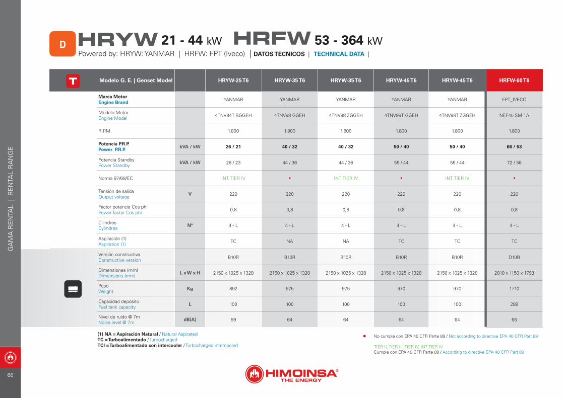
Modelo G. E. | Genset Model HRYW-25 T6 HRYW-35 T6 HRYW-35 T6 HRYW-45 T6 HRYW-45 T6 HRFW-60 T6
Marca Motor Engine Brand YANMAR YANMAR YANMAR YANMAR YANMAR FPT_IVECO
Modelo Motor Engine Model 4TNV84T BGGEH 4TNV98 GGEH 4TNV98 ZGGEH 4TNV98T GGEH 4TNV98T ZGGEH NEF45 SM 1A
R.P.M. 1.800 1.800 1.800 1.800 1.800 1.800
Potencia P.R.P. Power P.R.P.
kVA / kW 26 / 21 40 / 32 40 / 32 50 / 40 50 / 40 66 / 53
Potencia StandbyPower Standby
kVA / kW 28 / 23 44 / 36 44 / 36 55 / 44 55 / 44 72 / 58
Norma 97/68/EC INT. TIER IV • INT. TIER IV • INT. TIER IV •
Tensión de salidaOutput voltage
V 220 220 220 220 220 220
Factor potencia Cos phiPower factor Cos phi 0,8 0,8 0,8 0,8 0,8 0,8
CilindrosCylindres
Nº 4 - L 4 - L 4 - L 4 - L 4 - L 4 - L
Aspiración (1)Aspiration (1) TC NA NA TC TC TC
Versión constructivaConstructive version B10R B10R B10R B10R B10R D10R
Dimensiones (mm) Dimensions (mm)
L x W x H 2150 x 1025 x 1328 2150 x 1025 x 1328 2150 x 1025 x 1328 2150 x 1025 x 1328 2150 x 1025 x 1328 2810 x 1150 x 1793
PesoWeight
Kg 892 975 975 970 970 1710
Capacidad depósitoFuel tank capacity
L 100 100 100 100 100 288
Nivel de ruido @ 7mNoise level @ 7m
dB(A) 59 64 64 64 64 66
(1) NA = Aspiración Natural / Natural AspiratedTC = Turboalimentado / TurbochargedTCI = Turboalimentado con intercooler / Turbocharged intercooled
GA
MA
RE
NTA
L |
RE
NTA
L R
AN
GE
Powered by: HRYW: YANMAR | HRFW: FPT (Iveco) | DATOS TECNICOS | TECHNICAL DATA | D HRYW HRFW21 - 44 kW 53 - 364 kW
• No cumple con EPA 40 CFR Parte 89 / Not according to directive EPA 40 CFR Part 89
TIER II, TIER III, TIER IV, INT. TIER IVCumple con EPA 40 CFR Parte 89 / According to directive EPA 40 CFR Part 89
66
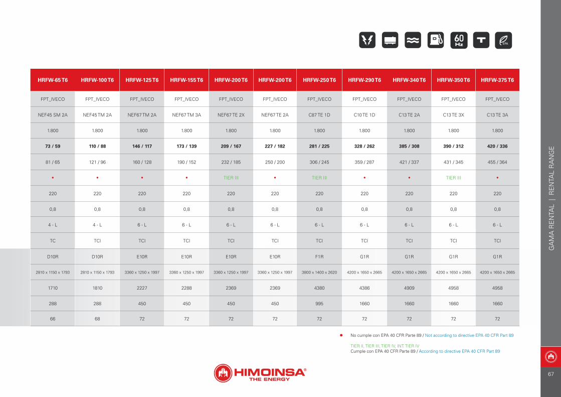
HRFW-65 T6 HRFW-100 T6 HRFW-125 T6 HRFW-155 T6 HRFW-200 T6 HRFW-200 T6 HRFW-250 T6 HRFW-290 T6 HRFW-340 T6 HRFW-350 T6 HRFW-375 T6
FPT_IVECO FPT_IVECO FPT_IVECO FPT_IVECO FPT_IVECO FPT_IVECO FPT_IVECO FPT_IVECO FPT_IVECO FPT_IVECO FPT_IVECO
NEF45 SM 2A NEF45 TM 2A NEF67 TM 2A NEF67 TM 3A NEF67 TE 2X NEF67 TE 2A C87 TE 1D C10 TE 1D C13 TE 2A C13 TE 3X C13 TE 3A
1.800 1.800 1.800 1.800 1.800 1.800 1.800 1.800 1.800 1.800 1.800
73 / 59 110 / 88 146 / 117 173 / 139 209 / 167 227 / 182 281 / 225 328 / 262 385 / 308 390 / 312 420 / 336
81 / 65 121 / 96 160 / 128 190 / 152 232 / 185 250 / 200 306 / 245 359 / 287 421 / 337 431 / 345 455 / 364
• • • • TIER III • TIER III • • TIER III •
220 220 220 220 220 220 220 220 220 220 220
0,8 0,8 0,8 0,8 0,8 0,8 0,8 0,8 0,8 0,8 0,8
4 - L 4 - L 6 - L 6 - L 6 - L 6 - L 6 - L 6 - L 6 - L 6 - L 6 - L
TC TCI TCI TCI TCI TCI TCI TCI TCI TCI TCI
D10R D10R E10R E10R E10R E10R F1R G1R G1R G1R G1R
2810 x 1150 x 1793 2810 x 1150 x 1793 3360 x 1250 x 1997 3360 x 1250 x 1997 3360 x 1250 x 1997 3360 x 1250 x 1997 3800 x 1400 x 2620 4200 x 1650 x 2665 4200 x 1650 x 2665 4200 x 1650 x 2665 4200 x 1650 x 2665
1710 1810 2227 2288 2369 2369 4380 4386 4909 4958 4958
288 288 450 450 450 450 995 1660 1660 1660 1660
66 68 72 72 72 72 72 72 72 72 72
GA
MA
RE
NTA
L |
RE
NTA
L R
AN
GE
• No cumple con EPA 40 CFR Parte 89 / Not according to directive EPA 40 CFR Part 89
TIER II, TIER III, TIER IV, INT. TIER IVCumple con EPA 40 CFR Parte 89 / According to directive EPA 40 CFR Part 89
67
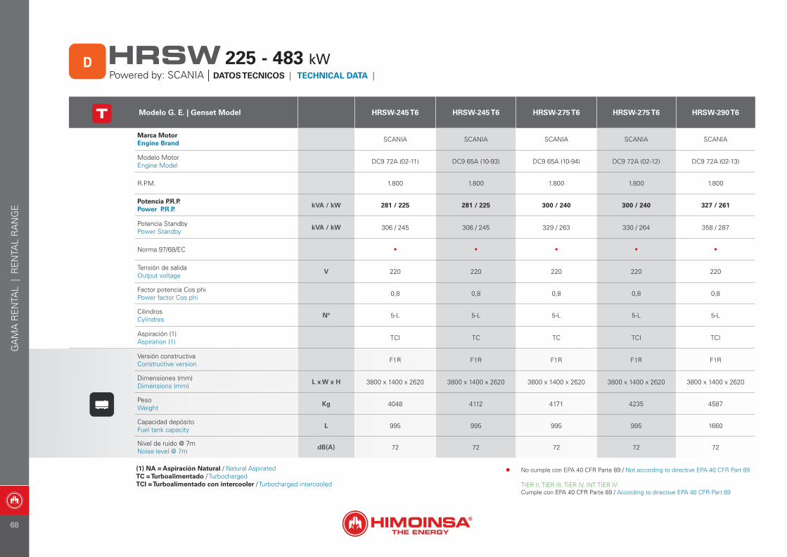
Modelo G. E. | Genset Model HRSW-245 T6 HRSW-245 T6 HRSW-275 T6 HRSW-275 T6 HRSW-290 T6
Marca Motor Engine Brand SCANIA SCANIA SCANIA SCANIA SCANIA
Modelo Motor Engine Model DC9 72A (02-11) DC9 65A (10-93) DC9 65A (10-94) DC9 72A (02-12) DC9 72A (02-13)
R.P.M. 1.800 1.800 1.800 1.800 1.800
Potencia P.R.P. Power P.R.P.
kVA / kW 281 / 225 281 / 225 300 / 240 300 / 240 327 / 261
Potencia StandbyPower Standby
kVA / kW 306 / 245 306 / 245 329 / 263 330 / 264 358 / 287
Norma 97/68/EC • • • • •
Tensión de salidaOutput voltage
V 220 220 220 220 220
Factor potencia Cos phiPower factor Cos phi 0,8 0,8 0,8 0,8 0,8
CilindrosCylindres
Nº 5-L 5-L 5-L 5-L 5-L
Aspiración (1)Aspiration (1) TCI TC TC TCI TCI
Versión constructivaConstructive version F1R F1R F1R F1R F1R
Dimensiones (mm) Dimensions (mm)
L x W x H 3800 x 1400 x 2620 3800 x 1400 x 2620 3800 x 1400 x 2620 3800 x 1400 x 2620 3800 x 1400 x 2620
PesoWeight
Kg 4048 4112 4171 4235 4587
Capacidad depósitoFuel tank capacity
L 995 995 995 995 1660
Nivel de ruido @ 7mNoise level @ 7m
dB(A) 72 72 72 72 72
(1) NA = Aspiración Natural / Natural AspiratedTC = Turboalimentado / TurbochargedTCI = Turboalimentado con intercooler / Turbocharged intercooled
Powered by: SCANIA | DATOS TECNICOS | TECHNICAL DATA | D HRSW 225 - 483 kW
GA
MA
RE
NTA
L |
RE
NTA
L R
AN
GE
• No cumple con EPA 40 CFR Parte 89 / Not according to directive EPA 40 CFR Part 89
TIER II, TIER III, TIER IV, INT. TIER IVCumple con EPA 40 CFR Parte 89 / According to directive EPA 40 CFR Part 89
68
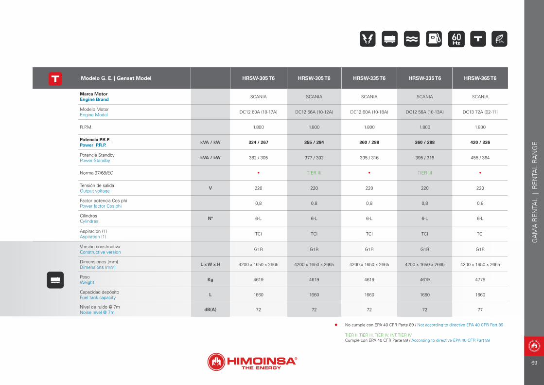
Modelo G. E. | Genset Model HRSW-305 T6 HRSW-305 T6 HRSW-335 T6 HRSW-335 T6 HRSW-365 T6
Marca Motor Engine Brand SCANIA SCANIA SCANIA SCANIA SCANIA
Modelo Motor Engine Model DC12 60A (10-17A) DC12 56A (10-12A) DC12 60A (10-18A) DC12 56A (10-13A) DC13 72A (02-11)
R.P.M. 1.800 1.800 1.800 1.800 1.800
Potencia P.R.P. Power P.R.P.
kVA / kW 334 / 267 355 / 284 360 / 288 360 / 288 420 / 336
Potencia StandbyPower Standby
kVA / kW 382 / 305 377 / 302 395 / 316 395 / 316 455 / 364
Norma 97/68/EC • TIER III • TIER III •
Tensión de salidaOutput voltage
V 220 220 220 220 220
Factor potencia Cos phiPower factor Cos phi 0,8 0,8 0,8 0,8 0,8
CilindrosCylindres
Nº 6-L 6-L 6-L 6-L 6-L
Aspiración (1)Aspiration (1) TCI TCI TCI TCI TCI
Versión constructivaConstructive version G1R G1R G1R G1R G1R
Dimensiones (mm) Dimensions (mm)
L x W x H 4200 x 1650 x 2665 4200 x 1650 x 2665 4200 x 1650 x 2665 4200 x 1650 x 2665 4200 x 1650 x 2665
PesoWeight
Kg 4619 4619 4619 4619 4779
Capacidad depósitoFuel tank capacity
L 1660 1660 1660 1660 1660
Nivel de ruido @ 7mNoise level @ 7m
dB(A) 72 72 72 72 77
GA
MA
RE
NTA
L |
RE
NTA
L R
AN
GE
• No cumple con EPA 40 CFR Parte 89 / Not according to directive EPA 40 CFR Part 89
TIER II, TIER III, TIER IV, INT. TIER IVCumple con EPA 40 CFR Parte 89 / According to directive EPA 40 CFR Part 89
69
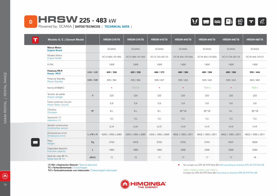
Modelo G. E. | Genset Model HRSW-370 T6 HRSW-370 T6 HRSW-410 T6 HRSW-440 T6 HRSW-440 T6 HRSW-445 T6 HRSW-480 T6
Marca Motor Engine Brand SCANIA SCANIA SCANIA SCANIA SCANIA SCANIA SCANIA
Modelo Motor Engine Model DC12 60A (10-19A) DC12 56A (10-15A) DC13 72A (02-12) DC16 43A (10-24A) DC16 45A (10-30A) DC13 72A (02-13) DC16 44A (10-27)
R.P.M. 1.800 1.800 1.800 1.800 1.800 1.800 1.800
Potencia P.R.P. Power P.R.P.
kVA / kW 420 / 336 420 / 336 466 / 373 480 / 384 480 / 384 480 / 384 555 / 444
Potencia StandbyPower Standby
kVA / kW 455 / 364 455 / 364 509 / 407 530 / 424 530 / 424 530 / 424 604 / 483
Norma 97/68/EC • TIER III • • TIER II • TIER II
Tensión de salidaOutput voltage
V 220 220 220 220 220 220 220
Factor potencia Cos phiPower factor Cos phi 0,8 0,8 0,8 0,8 0,8 0,8 0,8
CilindrosCylindres
Nº 6-L 6-L 6-L 90º V8 90º V8 6-L 90º V8
Aspiración (1)Aspiration (1) TCI TCI TCI TCI TCI TCI TCI
Versión constructivaConstructive version G1R G1R G1R H1R H1R H1R H1R
Dimensiones (mm) Dimensions (mm)
L x W x H 4200 x 1650 x 2665 4200 x 1650 x 2665 4200 x 1650 x 2665 4602 x 1850 x 2811 4602 x 1850 x 2811 4602 x 1850 x 2811 4602 x 1850 x 2811
PesoWeight
Kg 4703 4919 5703 5703 5703 5437 5936
Capacidad depósitoFuel tank capacity
L 1660 1660 1660 2090 2090 2090 2090
Nivel de ruido @ 7mNoise level @ 7m
dB(A) 72 72 77 77 77 77 76
(1) NA = Aspiración Natural / Natural AspiratedTC = Turboalimentado / TurbochargedTCI = Turboalimentado con intercooler / Turbocharged intercooled
Powered by: SCANIA | DATOS TECNICOS | TECHNICAL DATA | D HRSW 225 - 483 kW
GA
MA
RE
NTA
L |
RE
NTA
L R
AN
GE
• No cumple con EPA 40 CFR Parte 89 / Not according to directive EPA 40 CFR Part 89
TIER II, TIER III, TIER IV, INT. TIER IVCumple con EPA 40 CFR Parte 89 / According to directive EPA 40 CFR Part 89
70
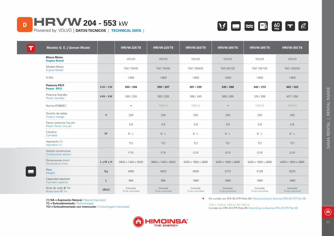
GA
MA
RE
NTA
L |
RE
NTA
L R
AN
GE
Modelo G. E. | Genset Model HRVW-225 T6 HRVW-220 T6 HRVW-250 T6 HRVW-300 T6 HRVW-305 T6 HRVW-355 T6
Marca Motor Engine Brand VOLVO VOLVO VOLVO VOLVO VOLVO VOLVO
Modelo Motor Engine Model TAD 734GE TAD 754GE TAD 1350GE TAD 941GE TAD 1351GE TAD 1352GE
R.P.M. 1.800 1.800 1.800 1.800 1.800 1.800
Potencia P.R.P. Power P.R.P.
kVA / kW 255 / 204 259 / 207 281 / 225 335 / 268 342 / 273 402 / 322
Potencia StandbyPower Standby
kVA / kW 285 / 228 283 / 226 306 / 245 369 / 295 374 / 299 437 / 350
Norma 97/68/EC • TIER III TIER III • TIER III TIER III
Tensión de salidaOutput voltage
V 220 220 220 220 220 220
Factor potencia Cos phiPower factor Cos phi 0,8 0,8 0,8 0,8 0,8 0,8
CilindrosCylindres
Nº 6 - L 6 - L 6 - L 6 - L 6 - L 6 - L
Aspiración (1)Aspiration (1) TCI TCI TCI TCI TCI TCI
Versión constructivaConstructive version F1R F1R G1R G1R G1R G1R
Dimensiones (mm) Dimensions (mm)
L x W x H 3800 x 1400 x 2620 3800 x 1400 x 2620 4200 x 1650 x 2665 4200 x 1650 x 2665 4200 x 1650 x 2665 4200 x 1650 x 2665
PesoWeight
Kg 4082 4023 4926 4772 5139 5223
Capacidad depósitoFuel tank capacity
L 995 995 1660 1660 1660 1660
Nivel de ruido @ 7mNoise level @ 7m
dB(A) ConsultarTo be consulted
ConsultarTo be consulted
ConsultarTo be consulted
ConsultarTo be consulted
ConsultarTo be consulted
ConsultarTo be consulted
(1) NA = Aspiración Natural / Natural AspiratedTC = Turboalimentado / TurbochargedTCI = Turboalimentado con intercooler / Turbocharged intercooled
Powered by: VOLVO | DATOS TECNICOS | TECHNICAL DATA | D HRVW 204 - 553 kW
• No cumple con EPA 40 CFR Parte 89 / Not according to directive EPA 40 CFR Part 89
TIER II, TIER III, TIER IV, INT. TIER IVCumple con EPA 40 CFR Parte 89 / According to directive EPA 40 CFR Part 89
71
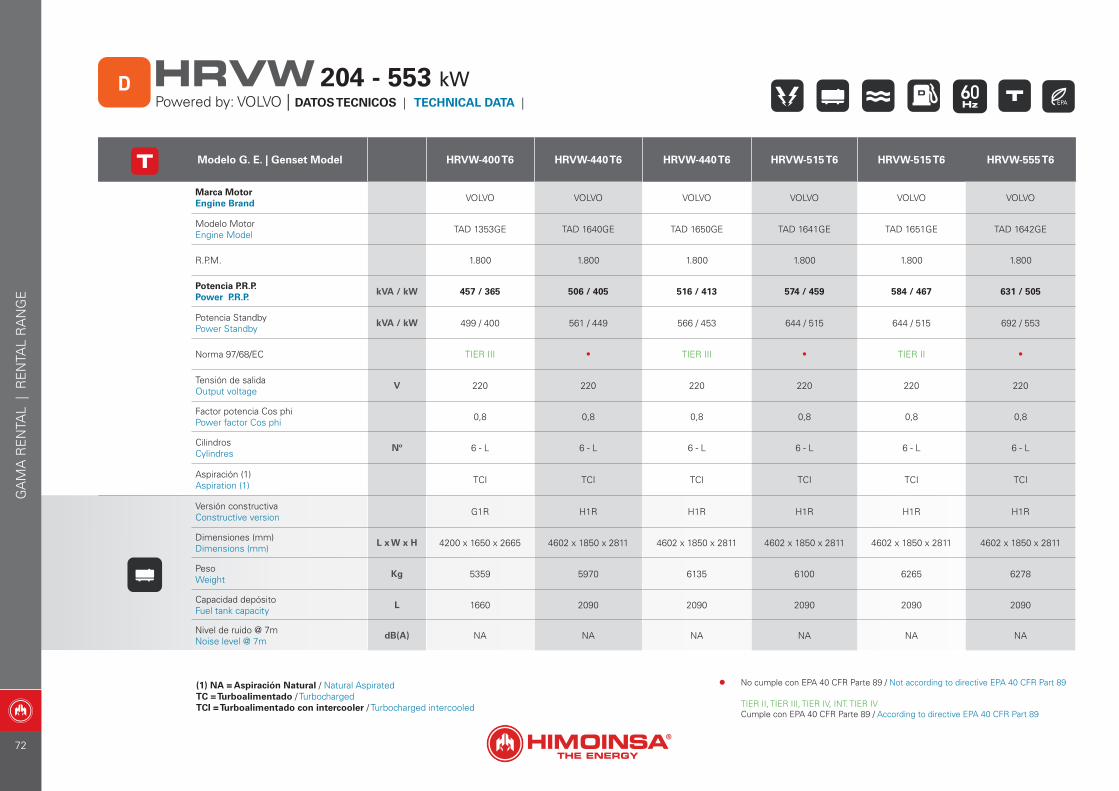
Modelo G. E. | Genset Model HRVW-400 T6 HRVW-440 T6 HRVW-440 T6 HRVW-515 T6 HRVW-515 T6 HRVW-555 T6
Marca Motor Engine Brand VOLVO VOLVO VOLVO VOLVO VOLVO VOLVO
Modelo Motor Engine Model TAD 1353GE TAD 1640GE TAD 1650GE TAD 1641GE TAD 1651GE TAD 1642GE
R.P.M. 1.800 1.800 1.800 1.800 1.800 1.800
Potencia P.R.P. Power P.R.P.
kVA / kW 457 / 365 506 / 405 516 / 413 574 / 459 584 / 467 631 / 505
Potencia StandbyPower Standby
kVA / kW 499 / 400 561 / 449 566 / 453 644 / 515 644 / 515 692 / 553
Norma 97/68/EC TIER III • TIER III • TIER II •
Tensión de salidaOutput voltage
V 220 220 220 220 220 220
Factor potencia Cos phiPower factor Cos phi 0,8 0,8 0,8 0,8 0,8 0,8
CilindrosCylindres
Nº 6 - L 6 - L 6 - L 6 - L 6 - L 6 - L
Aspiración (1)Aspiration (1) TCI TCI TCI TCI TCI TCI
Versión constructivaConstructive version G1R H1R H1R H1R H1R H1R
Dimensiones (mm) Dimensions (mm)
L x W x H 4200 x 1650 x 2665 4602 x 1850 x 2811 4602 x 1850 x 2811 4602 x 1850 x 2811 4602 x 1850 x 2811 4602 x 1850 x 2811
PesoWeight
Kg 5359 5970 6135 6100 6265 6278
Capacidad depósitoFuel tank capacity
L 1660 2090 2090 2090 2090 2090
Nivel de ruido @ 7mNoise level @ 7m
dB(A) NA NA NA NA NA NA
(1) NA = Aspiración Natural / Natural AspiratedTC = Turboalimentado / TurbochargedTCI = Turboalimentado con intercooler / Turbocharged intercooled
Powered by: VOLVO | DATOS TECNICOS | TECHNICAL DATA | D HRVW 204 - 553 kW
GA
MA
RE
NTA
L |
RE
NTA
L R
AN
GE
• No cumple con EPA 40 CFR Parte 89 / Not according to directive EPA 40 CFR Part 89
TIER II, TIER III, TIER IV, INT. TIER IVCumple con EPA 40 CFR Parte 89 / According to directive EPA 40 CFR Part 89
72
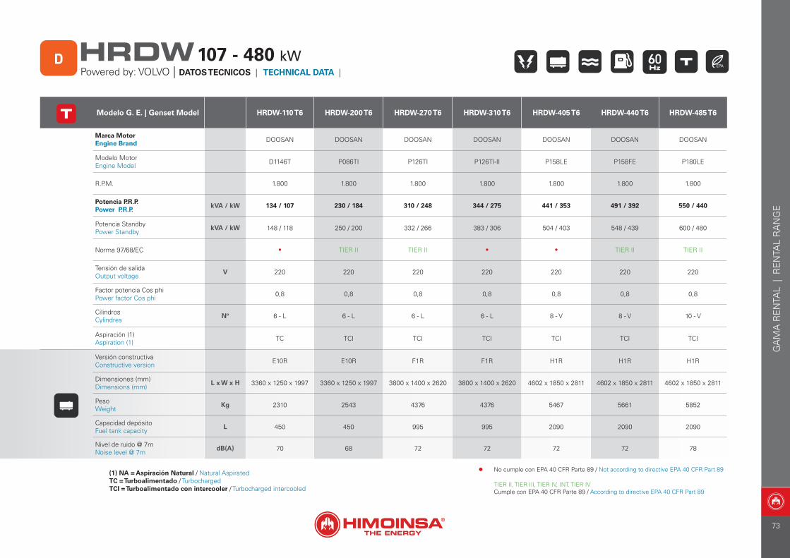
GA
MA
RE
NTA
L |
RE
NTA
L R
AN
GE
Modelo G. E. | Genset Model HRDW-110 T6 HRDW-200 T6 HRDW-270 T6 HRDW-310 T6 HRDW-405 T6 HRDW-440 T6 HRDW-485 T6
Marca Motor Engine Brand DOOSAN DOOSAN DOOSAN DOOSAN DOOSAN DOOSAN DOOSAN
Modelo Motor Engine Model D1146T P086TI P126TI P126TI-II P158LE P158FE P180LE
R.P.M. 1.800 1.800 1.800 1.800 1.800 1.800 1.800
Potencia P.R.P. Power P.R.P.
kVA / kW 134 / 107 230 / 184 310 / 248 344 / 275 441 / 353 491 / 392 550 / 440
Potencia StandbyPower Standby
kVA / kW 148 / 118 250 / 200 332 / 266 383 / 306 504 / 403 548 / 439 600 / 480
Norma 97/68/EC • TIER II TIER II • • TIER II TIER II
Tensión de salidaOutput voltage
V 220 220 220 220 220 220 220
Factor potencia Cos phiPower factor Cos phi 0,8 0,8 0,8 0,8 0,8 0,8 0,8
CilindrosCylindres
Nº 6 - L 6 - L 6 - L 6 - L 8 - V 8 - V 10 - V
Aspiración (1)Aspiration (1) TC TCI TCI TCI TCI TCI TCI
Versión constructivaConstructive version E10R E10R F1R F1R H1R H1R H1R
Dimensiones (mm) Dimensions (mm)
L x W x H 3360 x 1250 x 1997 3360 x 1250 x 1997 3800 x 1400 x 2620 3800 x 1400 x 2620 4602 x 1850 x 2811 4602 x 1850 x 2811 4602 x 1850 x 2811
PesoWeight
Kg 2310 2543 4376 4376 5467 5661 5852
Capacidad depósitoFuel tank capacity
L 450 450 995 995 2090 2090 2090
Nivel de ruido @ 7mNoise level @ 7m
dB(A) 70 68 72 72 72 72 78
(1) NA = Aspiración Natural / Natural AspiratedTC = Turboalimentado / TurbochargedTCI = Turboalimentado con intercooler / Turbocharged intercooled
Powered by: VOLVO | DATOS TECNICOS | TECHNICAL DATA | D HRDW107 - 480 kW
• No cumple con EPA 40 CFR Parte 89 / Not according to directive EPA 40 CFR Part 89
TIER II, TIER III, TIER IV, INT. TIER IVCumple con EPA 40 CFR Parte 89 / According to directive EPA 40 CFR Part 89
73
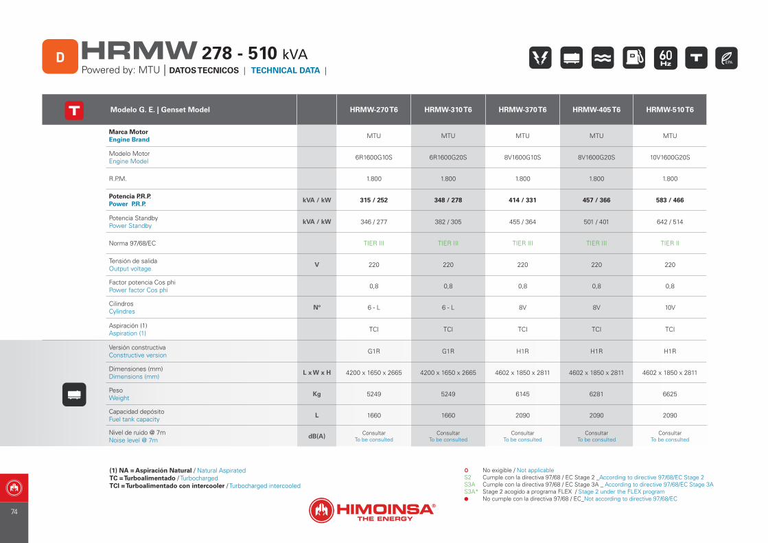
Modelo G. E. | Genset Model HRMW-270 T6 HRMW-310 T6 HRMW-370 T6 HRMW-405 T6 HRMW-510 T6
Marca Motor Engine Brand MTU MTU MTU MTU MTU
Modelo Motor Engine Model 6R1600G10S 6R1600G20S 8V1600G10S 8V1600G20S 10V1600G20S
R.P.M. 1.800 1.800 1.800 1.800 1.800
Potencia P.R.P. Power P.R.P.
kVA / kW 315 / 252 348 / 278 414 / 331 457 / 366 583 / 466
Potencia StandbyPower Standby
kVA / kW 346 / 277 382 / 305 455 / 364 501 / 401 642 / 514
Norma 97/68/EC TIER III TIER III TIER III TIER III TIER II
Tensión de salidaOutput voltage
V 220 220 220 220 220
Factor potencia Cos phiPower factor Cos phi 0,8 0,8 0,8 0,8 0,8
CilindrosCylindres
Nº 6 - L 6 - L 8V 8V 10V
Aspiración (1)Aspiration (1) TCI TCI TCI TCI TCI
Versión constructivaConstructive version G1R G1R H1R H1R H1R
Dimensiones (mm) Dimensions (mm)
L x W x H 4200 x 1650 x 2665 4200 x 1650 x 2665 4602 x 1850 x 2811 4602 x 1850 x 2811 4602 x 1850 x 2811
PesoWeight
Kg 5249 5249 6145 6281 6625
Capacidad depósitoFuel tank capacity
L 1660 1660 2090 2090 2090
Nivel de ruido @ 7mNoise level @ 7m
dB(A) ConsultarTo be consulted
ConsultarTo be consulted
ConsultarTo be consulted
ConsultarTo be consulted
ConsultarTo be consulted
(1) NA = Aspiración Natural / Natural AspiratedTC = Turboalimentado / TurbochargedTCI = Turboalimentado con intercooler / Turbocharged intercooled
S2S3AS3A*
No exigible / Not applicableCumple con la directiva 97/68 / EC Stage 2 _According to directive 97/68/EC Stage 2Cumple con la directiva 97/68 / EC Stage 3A _ According to directive 97/68/EC Stage 3AStage 2 acogido a programa FLEX / Stage 2 under the FLEX programNo cumple con la directiva 97/68 / EC_Not according to directive 97/68/EC
Powered by: MTU | DATOS TECNICOS | TECHNICAL DATA | D HRMW 278 - 510 kVA
74
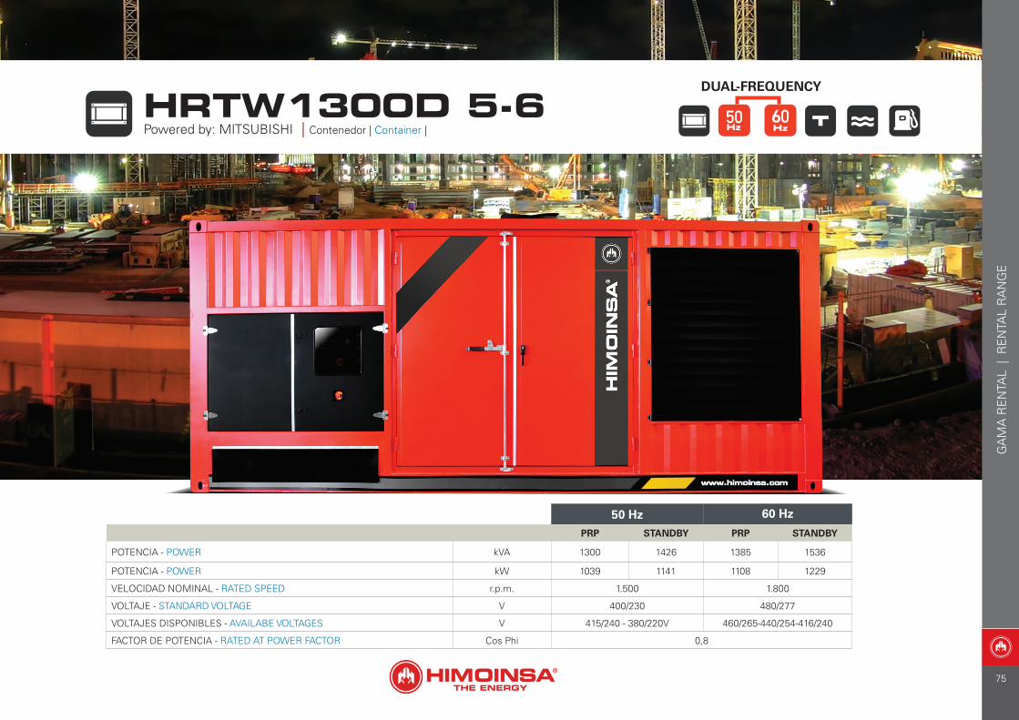
HRTW1300D 5-6Powered by: MITSUBISHI | Contenedor | Container |
DUAL-FREQUENCY
50 Hz 60 Hz
PRP STANDBY PRP STANDBY
POTENCIA - POWER kVA 1300 1426 1385 1536
POTENCIA - POWER kW 1039 1141 1108 1229
VELOCIDAD NOMINAL - RATED SPEED r.p.m. 1.500 1.800
VOLTAJE - STANDARD VOLTAGE V 400/230 480/277
VOLTAJES DISPONIBLES - AVAILABE VOLTAGES V 415/240 - 380/220V 460/265-440/254-416/240
FACTOR DE POTENCIA - RATED AT POWER FACTOR Cos Phi 0,8
GA
MA
RE
NTA
L |
RE
NTA
L R
AN
GE
75
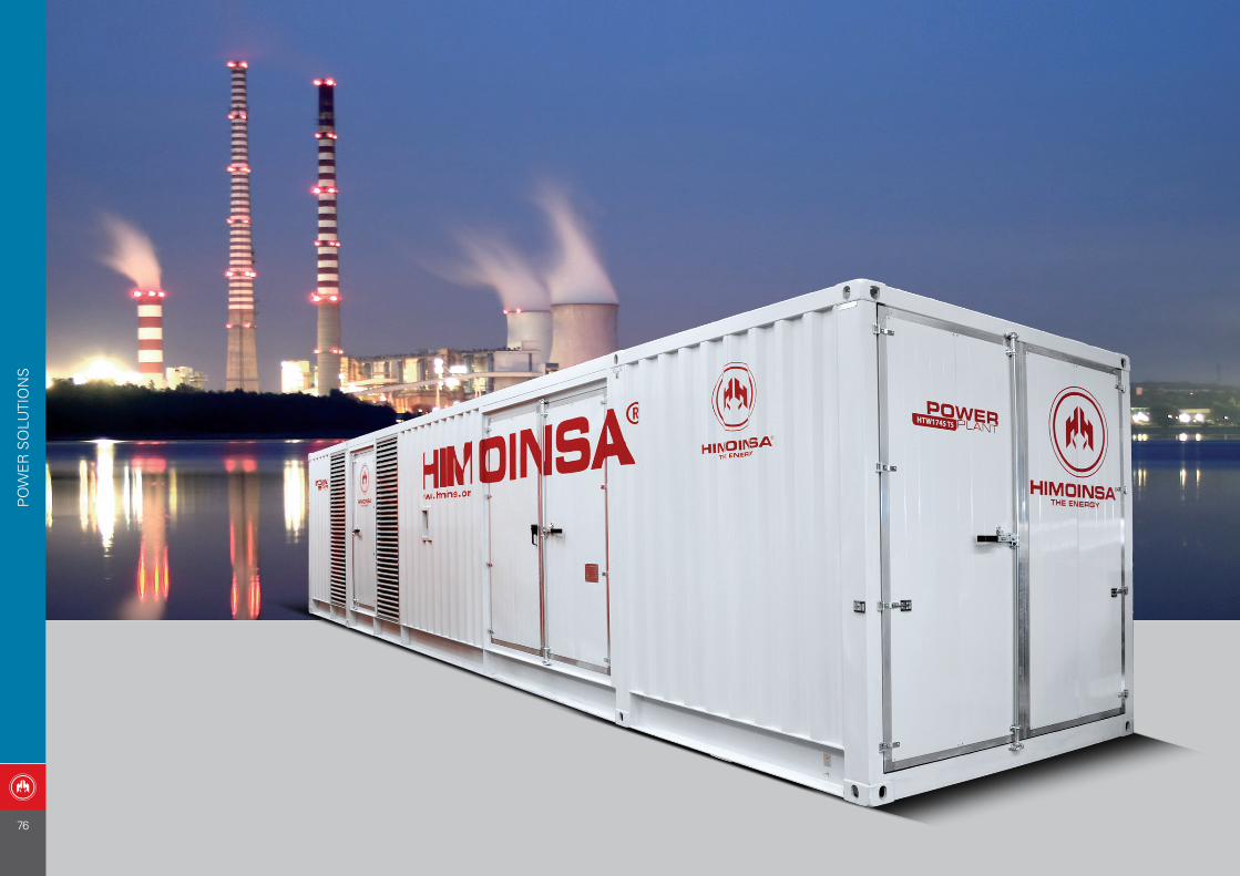
PO
WE
R S
OLU
TIO
NS
76
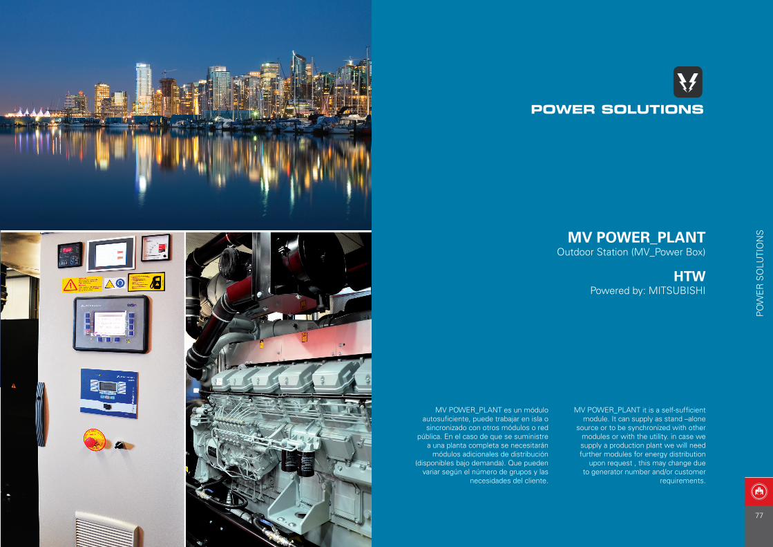
MV POWER_PLANT Outdoor Station (MV_Power Box)
HTWPowered by: MITSUBISHI
MV POWER_PLANT es un módulo autosuficiente, puede trabajar en isla o sincronizado con otros módulos o red
pública. En el caso de que se suministre a una planta completa se necesitarán
módulos adicionales de distribución (disponibles bajo demanda). Que pueden
variar según el número de grupos y las necesidades del cliente.
MV POWER_PLANT it is a self-sufficient module. It can supply as stand –alone
source or to be synchronized with other modules or with the utility. in case we supply a production plant we will need further modules for energy distribution
upon request , this may change due to generator number and/or customer
requirements.
POWER SOLUTIONS
PO
WE
R S
OLU
TIO
NS
77
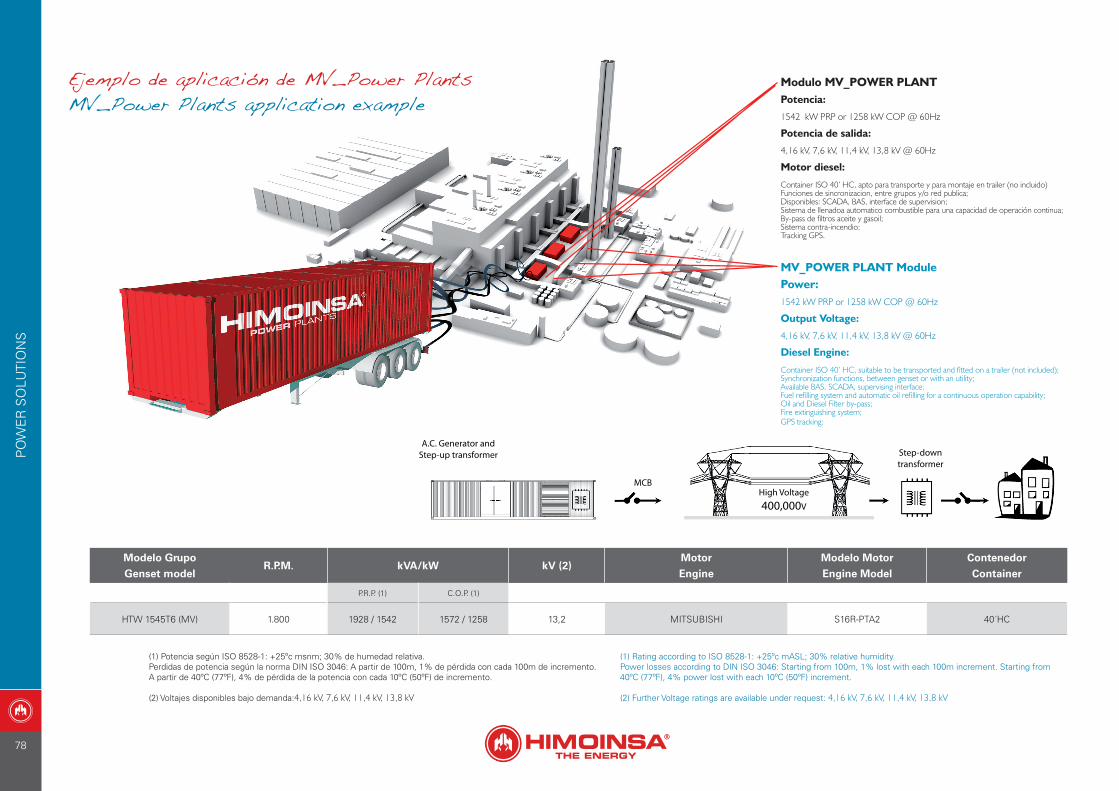
Ejemplo de aplicación de MV_Power PlantsMV_Power Plants application example
Modulo MV_POWER PLANTPotencia:
1542 kW PRP or 1258 kW COP @ 60Hz
Potencia de salida:
4,16 kV, 7,6 kV, 11,4 kV, 13,8 kV @ 60Hz
Motor diesel:
Container ISO 40’ HC, apto para transporte y para montaje en trailer (no incluido)Funciones de sincronizacion, entre grupos y/o red publica;Disponibles: SCADA, BAS, interface de supervision;Sistema de llenadoa automatico combustible para una capacidad de operación continua;By-pass de filtros aceite y gasoil;Sistema contra-incendio;Tracking GPS.
MV_POWER PLANT ModulePower:1542 kW PRP or 1258 kW COP @ 60Hz
Output Voltage:
4,16 kV, 7,6 kV, 11,4 kV, 13,8 kV @ 60Hz
Diesel Engine:
Container ISO 40’ HC, suitable to be transported and fitted on a trailer (not included);Synchronization functions, between genset or with an utility;Available BAS, SCADA, supervising interface;Fuel refilling system and automatic oil refilling for a continuous operation capability;Oil and Diesel Filter by-pass;Fire extinguishing system;GPS tracking;
Modelo Grupo
Genset modelR.P.M. kVA/kW kV (2)
Motor
Engine
Modelo Motor
Engine Model
Contenedor
Container
P.R.P. (1) C.O.P. (1)
HTW 1545T6 (MV) 1.800 1928 / 1542 1572 / 1258 13,2 MITSUBISHI S16R-PTA2 40´HC
(1) Potencia según ISO 8528-1: +25ºc msnm; 30% de humedad relativa.Perdidas de potencia según la norma DIN ISO 3046: A partir de 100m, 1% de pérdida con cada 100m de incremento.A partir de 40ºC (77ºF), 4% de pérdida de la potencia con cada 10ºC (50ºF) de incremento.
(2) Voltajes disponibles bajo demanda:4,16 kV, 7,6 kV, 11,4 kV, 13,8 kV
(1) Rating according to ISO 8528-1: +25ºc mASL; 30% relative humidity.Power losses according to DIN ISO 3046: Starting from 100m, 1% lost with each 100m increment. Starting from40ºC (77ºF), 4% power lost with each 10ºC (50ºF) increment.
(2) Further Voltage ratings are available under request: 4,16 kV, 7,6 kV, 11,4 kV, 13,8 kV
PO
WE
R S
OLU
TIO
NS
78
56
APLICACIONES_APPLICATIONS:
Campings_CampsitesCasas de Campo_Country houses
Caravanas_CaravansGranjas_Farms
Mercados_MarketsTalleres_Workshops
SERIES GASOILDIESEL SERIES:
Powered by: LOMBARDINIPowered by: HATZ
HLAHZA
GA
MA
PO
RTA
TIL
| P
OR
TAB
LE R
AN
GE
GAMA PORTATILPORTABLE RANGE
79
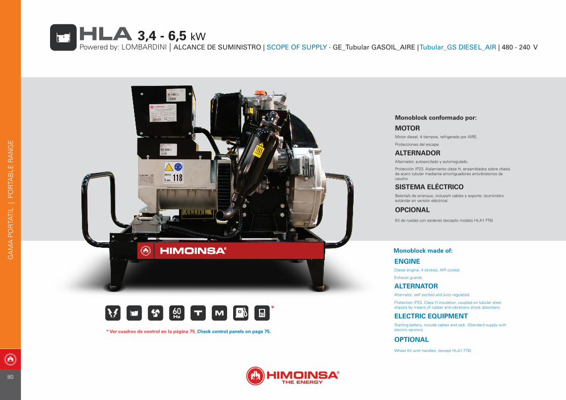
Monoblock conformado por:
MOTORMotor diesel, 4 tiempos, refrigerado por AIRE.
Protecciones del escape.
ALTERNADORAlternador, autoexcitado y autorregulado.
Protección IP23. Aislamiento clase H, ensamblados sobre chasis de acero tubular mediante amortiguadores antivibratorios de caucho.
SISTEMA ELÉCTRICOBatería/s de arranque, incluye/n cables y soporte. (suministro estándar en versión eléctrica).
OPCIONALKit de ruedas con asideras (excepto modelo HLA1-7T6)
Monoblock made of:
ENGINEDiesel engine, 4 strokes, AIR cooled.
Exhaust guards.
ALTERNATORAlternator, self excited and auto regulated.
Protection IP23. Class H insulation, coupled on tubular steel chassis by means of rubber anti-vibrations shock absorbers.
ELECTRIC EQUIPMENTStarting battery, include cables and rack. (Standard supply withelectric version).
OPTIONAL
Wheel Kit with handles. (except HLA1-7T6)
GA
MA
PO
RTA
TIL
| P
OR
TAB
LE R
AN
GE
Powered by: LOMBARDINI | ALCANCE DE SUMINISTRO | SCOPE OF SUPPLY · GE_Tubular GASOIL_AIRE | Tubular_GS DIESEL_AIR | 480 - 240 V HLA 3,4 - 6,5 kW
*
* Ver cuadros de control en la página 75_Check control panels on page 75.
80
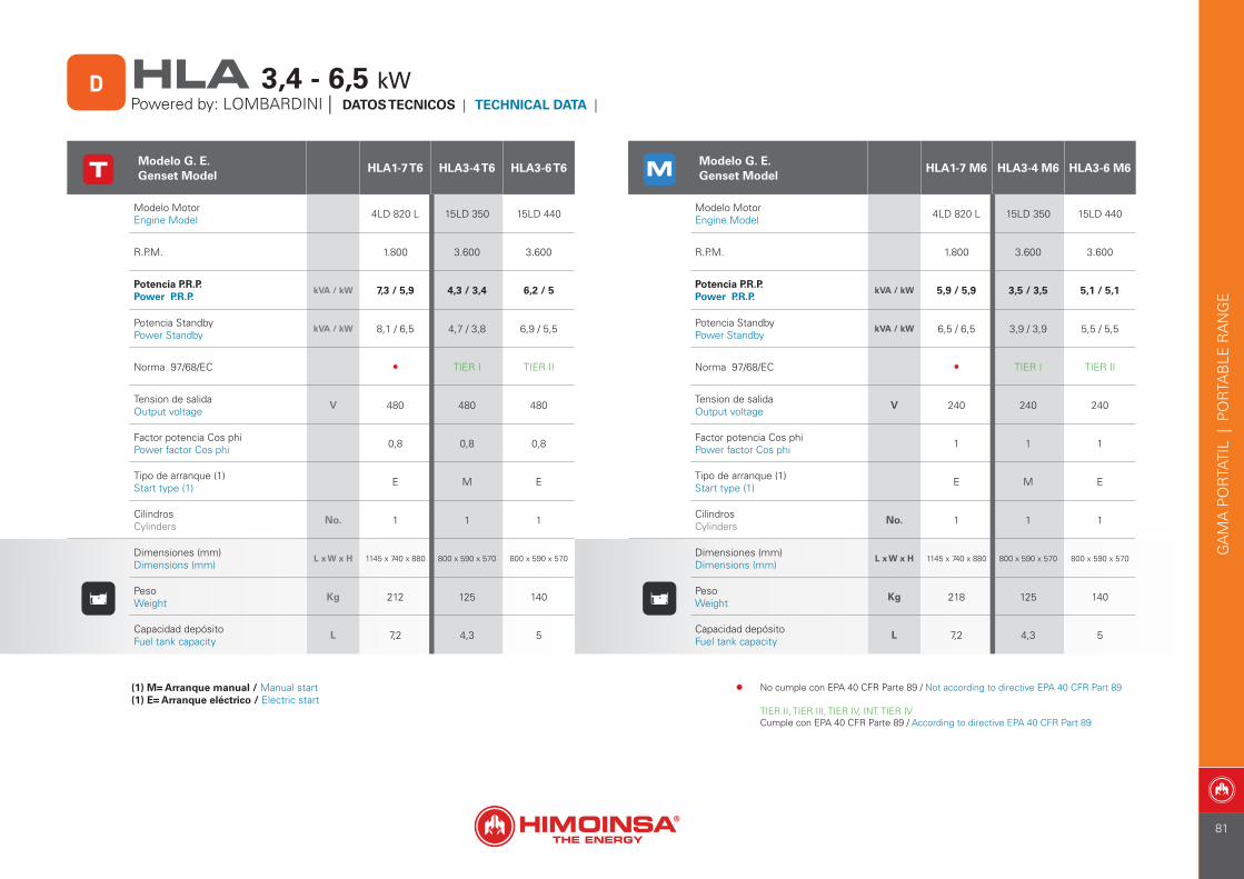
Modelo G. E. Genset Model
HLA1-7 T6 HLA3-4 T6 HLA3-6 T6
Modelo MotorEngine Model 4LD 820 L 15LD 350 15LD 440
R.P.M. 1.800 3.600 3.600
Potencia P.R.P.Power P.R.P.
kVA / kW 7,3 / 5,9 4,3 / 3,4 6,2 / 5
Potencia StandbyPower Standby
kVA / kW 8,1 / 6,5 4,7 / 3,8 6,9 / 5,5
Norma 97/68/EC • TIER I TIER II
Tension de salidaOutput voltage
V 480 480 480
Factor potencia Cos phiPower factor Cos phi 0,8 0,8 0,8
Tipo de arranque (1)Start type (1) E M E
CilindrosCylinders
No. 1 1 1
Dimensiones (mm)Dimensions (mm)
L x W x H 1145 x 740 x 880 800 x 590 x 570 800 x 590 x 570
PesoWeight
Kg 212 125 140
Capacidad depósitoFuel tank capacity
L 7,2 4,3 5
(1) M= Arranque manual / Manual start(1) E= Arranque eléctrico / Electric start
Modelo G. E. Genset Model
HLA1-7 M6 HLA3-4 M6 HLA3-6 M6
Modelo MotorEngine Model 4LD 820 L 15LD 350 15LD 440
R.P.M. 1.800 3.600 3.600
Potencia P.R.P.Power P.R.P.
kVA / kW 5,9 / 5,9 3,5 / 3,5 5,1 / 5,1
Potencia StandbyPower Standby
kVA / kW 6,5 / 6,5 3,9 / 3,9 5,5 / 5,5
Norma 97/68/EC • TIER I TIER II
Tension de salidaOutput voltage
V 240 240 240
Factor potencia Cos phiPower factor Cos phi 1 1 1
Tipo de arranque (1)Start type (1) E M E
CilindrosCylinders
No. 1 1 1
Dimensiones (mm)Dimensions (mm)
L x W x H 1145 x 740 x 880 800 x 590 x 570 800 x 590 x 570
PesoWeight
Kg 218 125 140
Capacidad depósitoFuel tank capacity
L 7,2 4,3 5
GA
MA
PO
RTA
TIL
| P
OR
TAB
LE R
AN
GE
HLA 3,4 - 6,5 kWPowered by: LOMBARDINI | DATOS TECNICOS | TECHNICAL DATA |
D
• No cumple con EPA 40 CFR Parte 89 / Not according to directive EPA 40 CFR Part 89
TIER II, TIER III, TIER IV, INT. TIER IVCumple con EPA 40 CFR Parte 89 / According to directive EPA 40 CFR Part 89
81
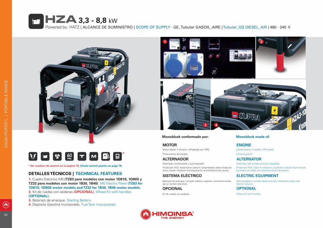
Monoblock conformado por:
MOTORMotor diesel, 4 tiempos, refrigerado por AIRE.
Protecciones del escape.
ALTERNADORAlternador, autoexcitado y autorregulado.
Protección IP23. Aislamiento clase H, ensamblados sobre chasis de acero tubular mediante amortiguadores antivibratorios de caucho.
SISTEMA ELÉCTRICOBatería/s de arranque, incluye/n cables y soporte. (suministro están-dar en versión eléctrica).
OPCIONALKit de ruedas con asideras
Monoblock made of:
ENGINEDiesel engine, 4 strokes, AIR cooled.
Exhaust guards.
ALTERNATORAlternator, self excited and auto regulated.
Protection IP23. Class H insulation, coupled on tubular steel chassis by means of rubber anti-vibrations shock absorbers.
ELECTRIC EQUIPMENTStarting battery, include cables and rack. (Standard supply withelectric version).
OPTIONALWheel Kit with handles.
1. Cuadro Eléctrico M0 (TZ63 para modelos con motor 1D81S, 1D90S y TZ32 para modelos con motor 1B30, 1B40). M0 Electric Panel (TZ63 for 1D81S, 1D90S motor models and TZ32 for 1B30, 1B40 motor models.2. Kit de ruedas con asideras (OPCIONAL). Wheel Kit with handles (OPTIONAL).3. Batería/s de arranque. Starting Battery.4. Deposito Gasolina Incorporado. Fuel Tank Incorporated.
DETALLES TÉCNICOS | TECHNICAL FEATURES
1
3 4
2
*
* Ver cuadros de control en la página 76_Check control panels on page 76.
GA
MA
PO
RTA
TIL
| P
OR
TAB
LE R
AN
GE
Powered by: HATZ | ALCANCE DE SUMINISTRO | SCOPE OF SUPPLY · GE_Tubular GASOIL_AIRE | Tubular_GS DIESEL_AIR | 480 - 240 V HZA 3,3 - 8,8 kW
82
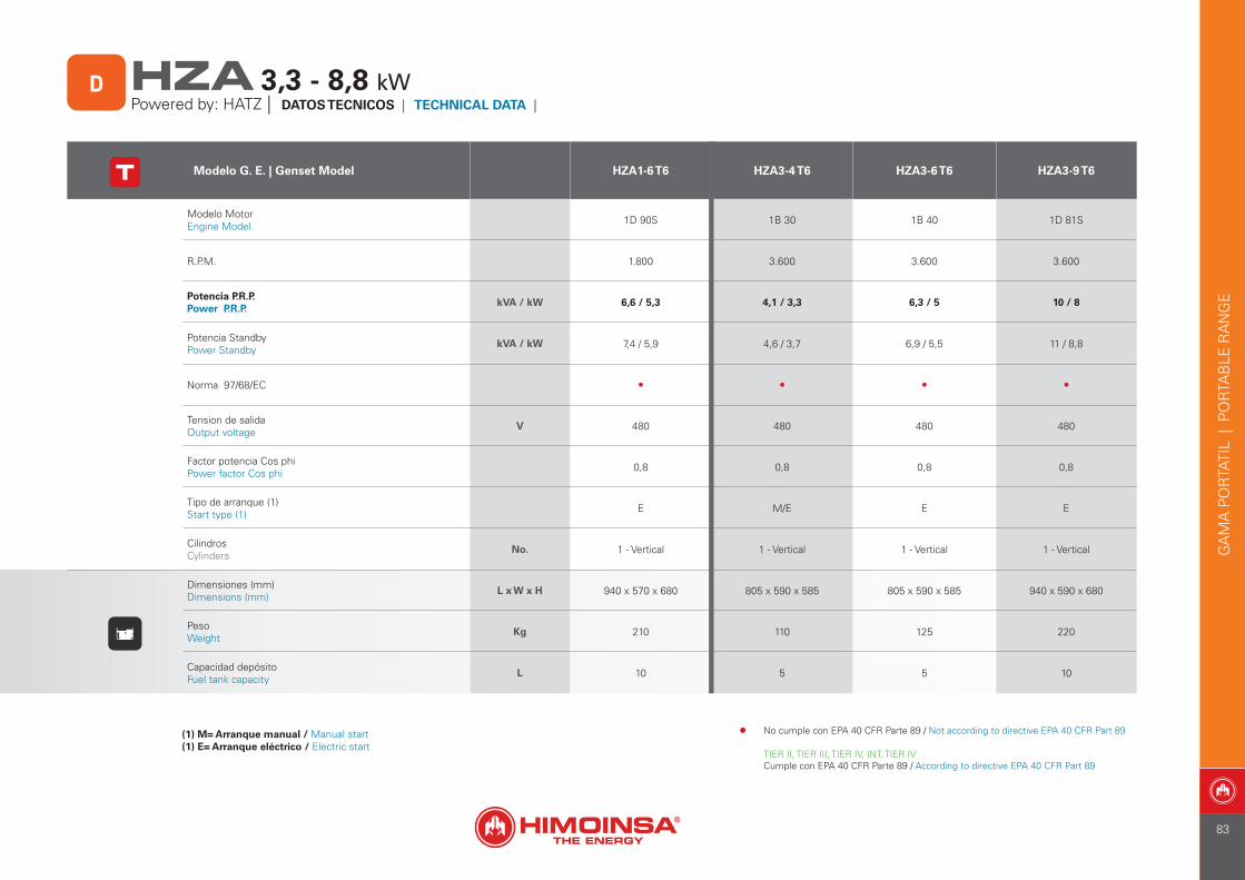
Modelo G. E. | Genset Model HZA1-6 T6 HZA3-4 T6 HZA3-6 T6 HZA3-9 T6
Modelo MotorEngine Model 1D 90S 1B 30 1B 40 1D 81S
R.P.M. 1.800 3.600 3.600 3.600
Potencia P.R.P.Power P.R.P.
kVA / kW 6,6 / 5,3 4,1 / 3,3 6,3 / 5 10 / 8
Potencia StandbyPower Standby
kVA / kW 7,4 / 5,9 4,6 / 3,7 6,9 / 5,5 11 / 8,8
Norma 97/68/EC • • • •
Tension de salidaOutput voltage
V 480 480 480 480
Factor potencia Cos phiPower factor Cos phi 0,8 0,8 0,8 0,8
Tipo de arranque (1)Start type (1) E M/E E E
CilindrosCylinders
No. 1 - Vertical 1 - Vertical 1 - Vertical 1 - Vertical
Dimensiones (mm)Dimensions (mm)
L x W x H 940 x 570 x 680 805 x 590 x 585 805 x 590 x 585 940 x 590 x 680
PesoWeight
Kg 210 110 125 220
Capacidad depósitoFuel tank capacity
L 10 5 5 10
(1) M= Arranque manual / Manual start(1) E= Arranque eléctrico / Electric start
GA
MA
PO
RTA
TIL
| P
OR
TAB
LE R
AN
GE
HZA 3,3 - 8,8 kWPowered by: HATZ | DATOS TECNICOS | TECHNICAL DATA |
D
• No cumple con EPA 40 CFR Parte 89 / Not according to directive EPA 40 CFR Part 89
TIER II, TIER III, TIER IV, INT. TIER IVCumple con EPA 40 CFR Parte 89 / According to directive EPA 40 CFR Part 89
83
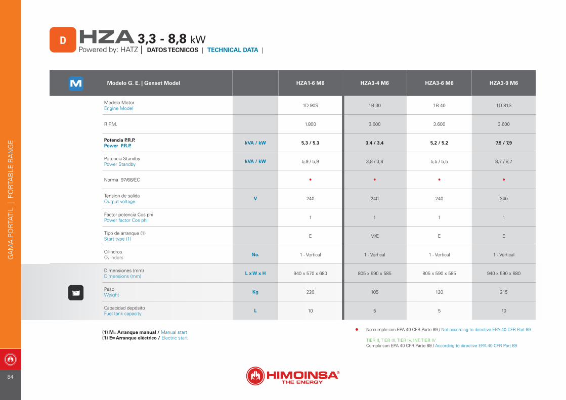
Modelo G. E. | Genset Model HZA1-6 M6 HZA3-4 M6 HZA3-6 M6 HZA3-9 M6
Modelo MotorEngine Model 1D 90S 1B 30 1B 40 1D 81S
R.P.M. 1.800 3.600 3.600 3.600
Potencia P.R.P.Power P.R.P.
kVA / kW 5,3 / 5,3 3,4 / 3,4 5,2 / 5,2 7,9 / 7,9
Potencia StandbyPower Standby
kVA / kW 5,9 / 5,9 3,8 / 3,8 5,5 / 5,5 8,7 / 8,7
Norma 97/68/EC • • • •
Tension de salidaOutput voltage
V 240 240 240 240
Factor potencia Cos phiPower factor Cos phi 1 1 1 1
Tipo de arranque (1)Start type (1) E M/E E E
CilindrosCylinders
No. 1 - Vertical 1 - Vertical 1 - Vertical 1 - Vertical
Dimensiones (mm)Dimensions (mm)
L x W x H 940 x 570 x 680 805 x 590 x 585 805 x 590 x 585 940 x 590 x 680
PesoWeight
Kg 220 105 120 215
Capacidad depósitoFuel tank capacity
L 10 5 5 10
(1) M= Arranque manual / Manual start(1) E= Arranque eléctrico / Electric start
HZA 3,3 - 8,8 kWPowered by: HATZ | DATOS TECNICOS | TECHNICAL DATA |
D
GA
MA
PO
RTA
TIL
| P
OR
TAB
LE R
AN
GE
• No cumple con EPA 40 CFR Parte 89 / Not according to directive EPA 40 CFR Part 89
TIER II, TIER III, TIER IV, INT. TIER IVCumple con EPA 40 CFR Parte 89 / According to directive EPA 40 CFR Part 89
84
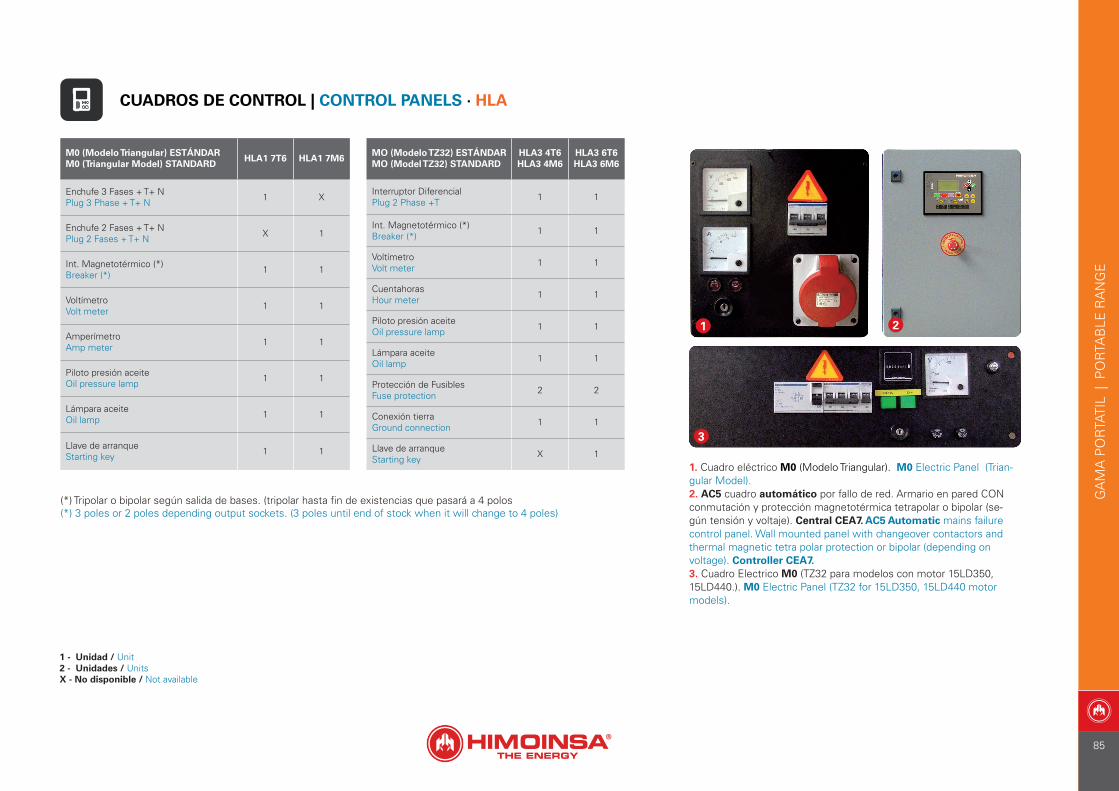
1. Cuadro eléctrico M0 (Modelo Triangular). M0 Electric Panel (Trian-gular Model).2. AC5 cuadro automático por fallo de red. Armario en pared CON conmutación y protección magnetotérmica tetrapolar o bipolar (se-gún tensión y voltaje). Central CEA7. AC5 Automatic mains failure control panel. Wall mounted panel with changeover contactors and thermal magnetic tetra polar protection or bipolar (depending on voltage). Controller CEA7.3. Cuadro Electrico M0 (TZ32 para modelos con motor 15LD350, 15LD440.). M0 Electric Panel (TZ32 for 15LD350, 15LD440 motor models).
21
3
M0 (Modelo Triangular) ESTÁNDAR M0 (Triangular Model) STANDARD
HLA1 7T6 HLA1 7M6
Enchufe 3 Fases + T+ NPlug 3 Phase + T+ N 1 X
Enchufe 2 Fases + T+ NPlug 2 Fases + T+ N X 1
Int. Magnetotérmico (*)Breaker (*) 1 1
VoltímetroVolt meter 1 1
Amperímetro Amp meter 1 1
Piloto presión aceiteOil pressure lamp 1 1
Lámpara aceite Oil lamp 1 1
Llave de arranqueStarting key 1 1
MO (Modelo TZ32) ESTÁNDARMO (Model TZ32) STANDARD
HLA3 4T6HLA3 4M6
HLA3 6T6HLA3 6M6
Interruptor Diferencial Plug 2 Phase +T 1 1
Int. Magnetotérmico (*)Breaker (*) 1 1
VoltímetroVolt meter 1 1
Cuentahoras Hour meter 1 1
Piloto presión aceiteOil pressure lamp 1 1
Lámpara aceite Oil lamp 1 1
Protección de Fusibles Fuse protection 2 2
Conexión tierraGround connection 1 1
Llave de arranqueStarting key X 1
(*) Tripolar o bipolar según salida de bases. (tripolar hasta fin de existencias que pasará a 4 polos(*) 3 poles or 2 poles depending output sockets. (3 poles until end of stock when it will change to 4 poles)
CUADROS DE CONTROL | CONTROL PANELS · HLA
1 - Unidad / Unit2 - Unidades / UnitsX - No disponible / Not available
GA
MA
PO
RTA
TIL
| P
OR
TAB
LE R
AN
GE
85
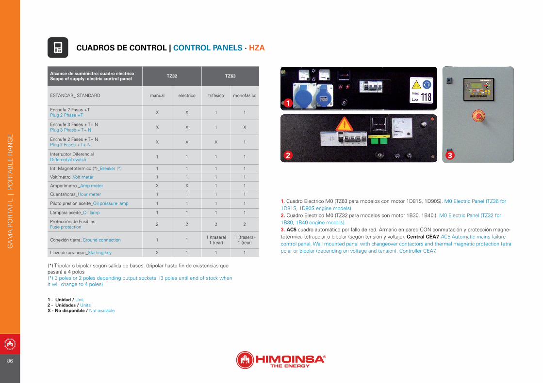
Alcance de suministro: cuadro eléctricoScope of supply: electric control panel TZ32 TZ63
ESTÁNDAR_ STANDARD manual eléctrico trifásico monofásico
Enchufe 2 Fases +TPlug 2 Phase +T X X 1 1
Enchufe 3 Fases + T+ NPlug 3 Phase + T+ N X X 1 X
Enchufe 2 Fases + T+ NPlug 2 Fases + T+ N X X X 1
Interruptor DiferencialDifferential switch 1 1 1 1
Int. Magnetotérmico (*)_Breaker (*) 1 1 1 1
Voltímetro_Volt meter 1 1 1 1
Amperímetro _Amp meter X X 1 1
Cuentahoras_Hour meter 1 1 1 1
Piloto presión aceite_Oil pressure lamp 1 1 1 1
Lámpara aceite_Oil lamp 1 1 1 1
Protección de Fusibles Fuse protection 2 2 2 2
Conexión tierra_Ground connection 1 1 1 (trasera)1 (rear)
1 (trasera)1 (rear)
Llave de arranque_Starting key X 1 1 1
2 3
1
1. Cuadro Electrico M0 (TZ63 para modelos con motor 1D81S, 1D90S). M0 Electric Panel (TZ36 for 1D81S, 1D90S engine models).2. Cuadro Electrico M0 (TZ32 para modelos con motor 1B30, 1B40.). M0 Electric Panel (TZ32 for 1B30, 1B40 engine models).3. AC5 cuadro automático por fallo de red. Armario en pared CON conmutación y protección magne-totérmica tetrapolar o bipolar (según tensión y voltaje). Central CEA7. AC5 Automatic mains failure control panel. Wall mounted panel with changeover contactors and thermal magnetic protection tetra polar or bipolar (depending on voltage and tension). Controller CEA7.
(*) Tripolar o bipolar según salida de bases. (tripolar hasta fin de existencias que pasará a 4 polos(*) 3 poles or 2 poles depending output sockets. (3 poles until end of stock when it will change to 4 poles)
CUADROS DE CONTROL | CONTROL PANELS · HZA
1 - Unidad / Unit2 - Unidades / UnitsX - No disponible / Not available
GA
MA
PO
RTA
TIL
| P
OR
TAB
LE R
AN
GE
86
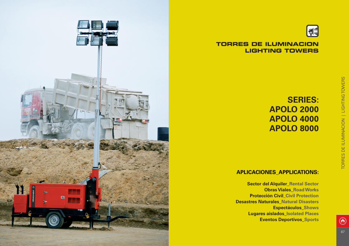
SERIES: APOLO 2000APOLO 4000APOLO 8000
APLICACIONES_APPLICATIONS:
Sector del Alquiler_Rental SectorObras Viales_Road Works
Protección Civil_Civil ProtectionDesastres Naturales_Natural Disasters
Espectáculos_ShowsLugares aislados_Isolated Places
Eventos Deportivos_Sports
TOR
RE
S D
E IL
UM
INA
CIO
N |
LIG
HTI
NG
TO
WE
RS
TORRES DE ILUMINACIONLIGHTING TOWERS
87
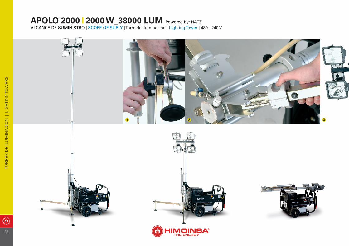
APOLO 2000 2000 W_38000 LUM Powered by: HATZALCANCE DE SUMINISTRO | SCOPE OF SUPLY | Torre de Iluminación | Lighting Tower | 480 - 240 V
1 2 3
TOR
RE
S D
E IL
UM
INA
CIO
N |
LIG
HTI
NG
TO
WE
RS
88
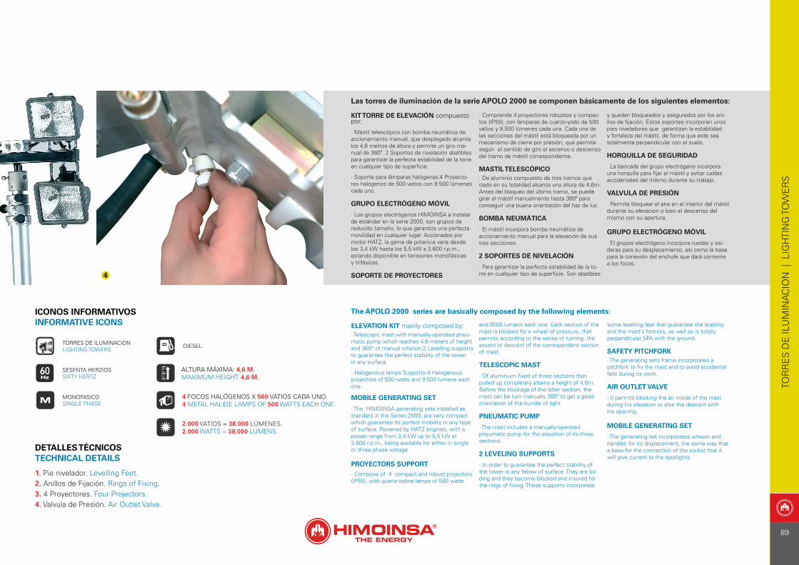
1. Pie nivelador. Levelling Feet. 2. Anillos de Fijación. Rings of Fixing. 3. 4 Proyectores. Four Projectors.4. Valvula de Presión. Air Outlet Valve.
4
Las torres de iluminación de la serie APOLO 2000 se componen básicamente de los siguientes elementos:
KIT TORRE DE ELEVACIÓN compuesto por:
· Mástil telescópico con bomba neumática de accionamiento manual, que desplegado alcanza los 4,6 metros de altura y permite un giro ma-nual de 360º. 2 Soportes de nivelación abatibles para garantizar la perfecta estabilidad de la torre en cualquier tipo de superficie.
· Soporte para lámparas halógenas.4 Proyecto-res halógenos de 500 vatios con 9.500 lúmenes cada uno. GRUPO ELECTRÓGENO MÓVIL
· Los grupos electrógenos HIMOINSA a instalar de estándar en la serie 2000, son grupos de reducido tamaño, lo que garantiza una perfecta movilidad en cualquier lugar. Accionados por motor HATZ, la gama de potencia varía desde los 3,4 kW hasta los 5,5 kW a 3.600 r.p.m., estando disponible en tensiones monofásicas y trifásicas.
SOPORTE DE PROYECTORES
· Comprende 4 proyectores robustos y compac-tos (IP55), con lámparas de cuarzo-yodo de 500 vatios y 9.500 lúmenes cada una. Cada una de las secciones del mástil está bloqueada por un mecanismo de cierre por presión, que permite según el sentido de giro el ascenso o descenso del tramo de mástil correspondiente.
MASTIL TELESCÓPICO· De aluminio compuesto de tres tramos que izado en su totalidad alcanza una altura de 4,6m. Antes del bloqueo del último tramo, se puede girar el mástil manualmente hasta 360º para conseguir una buena orientación del haz de luz.
BOMBA NEUMÁTICA
· El mástil incorpora bomba neumática de accionamiento manual para la elevación de sus tres secciones.
2 SOPORTES DE NIVELACIÓN
· Para garantizar la perfecta estabilidad de la to-rre en cualquier tipo de superficie. Son abatibles
y quedan bloqueados y asegurados por los ani-llos de fijación. Estos soportes incorporan unos pies niveladores que garantizan la estabilidad y fortaleza del mástil, de forma que este sea totalmente perpendicular con el suelo.
HORQUILLA DE SEGURIDAD
· La bancada del grupo electrógeno incorpora una horquilla para fijar el mástil y evitar caídas accidentales del mismo durante su trabajo.
VALVULA DE PRESIÓN
· Permite bloquear el aire en el interior del mástil durante su elevación o bien el descenso del mismo con su apertura.
GRUPO ELECTRÓGENO MÓVIL
· El grupos electrógeno incorpora ruedas y asi-deras para su desplazamiento, así como la base para la conexión del enchufe que dará corriente a los focos.
ICONOS INFORMATIVOSINFORMATIVE ICONS
DIESEL
SESENTA HERZIOSSIXTY HERTZ
TORRES DE ILUMINACIONLIGHTING TOWERS
MONOFASICOSINGLE PHASE
4 FOCOS HALÓGENOS X 500 VATIOS CADA UNO. 4 METAL HALIDE LAMPS OF 500 WATTS EACH ONE.
ALTURA MÁXIMA: 4,6 M. MAXIMUM HEIGHT: 4,6 M.
2.000 VATIOS = 38.000 LÚMENES. 2.000 WATTS = 38.000 LUMENS.
The APOLO 2000 series are basically composed by the following elements:
ELEVATION KIT mainly composed by: · Telescopic mast with manually-operated pneu-matic pump which reaches 4.6 meters of height and 360° of manual rotation.2 Levelling supports to guarantee the perfect stability of the tower in any surface.
· Halogenous lamps Supports.4 Halogenous projectors of 500-watts and 9.500 lumens each one. MOBILE GENERATING SET
· The HIMOINSA generating sets installed as standard in the Series 2000, are very compact which guarantee its perfect mobility in any type of surface. Powered by HATZ engines, with a power range from 3,4 kW up to 5,5 kW at3.600 r.p.m., being available for either in single or three phase voltage.
PROYECTORS SUPPORT· Compose of 4 compact and robust projectors (IP55), with quartz-iodine lamps of 500 watts
and 9500 lumens each one. Each section of the mast is blocked for a wheel of pressure, that permits according to the sense of turning, the ascent or descent of the correspondent section of mast.
TELESCOPIC MAST
· Of aluminium fixed of three sections than pulled up completely attains a height of 4,6m. Before the blockage of the latter section, the mast can be turn manually 360º to get a good orientation of the bundle of light.
PNEUMATIC PUMP
· The mast includes a manually-operated pneumatic pump for the elevation of its three sections.
2 LEVELING SUPPORTS
· In order to guarantee the perfect stability of the tower in any fellow of surface. They are fol-ding and they become blocked and insured for the rings of fixing. These supports incorporate
some levelling feet that guarantee the stability and the mast’s fortress, as well as is totally perpendicular SFA with the ground.
SAFETY PITCHFORK· The generating sets frame incorporates a pitchfork to fix the mast and to avoid accidental falls during its work.
AIR OUTLET VALVE
· It permits blocking the air inside of the mast during his elevation or else the descent with his opening.
MOBILE GENERATING SET
· The generating set incorporates wheels and handles for its displacement, the same way that a base for the connection of the socket that it will give current to the spotlights.
DETALLES TÉCNICOS TECHNICAL DETAILS
TOR
RE
S D
E IL
UM
INA
CIO
N |
LIG
HTI
NG
TO
WE
RS
89
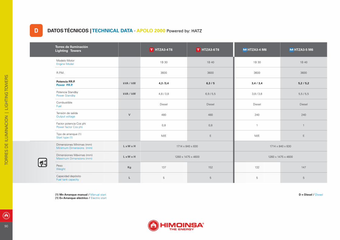
Torres de IluminaciónLighting Towers HTZA3-4 T6 HTZA3-6 T6 HTZA3-4 M6 HTZA3-5 M6
Modelo Motor Engine Model 1B 30 1B 40 1B 30 1B 40
R.P.M. 3600 3600 3600 3600
Potencia P.R.P. Power P.R.P.
kVA / kW 4,3 /3,4 6,3 / 5 3,4 / 3,4 5,2 / 5,2
Potencia StandbyPower Standby
kVA / kW 4,8 / 3,8 6,9 / 5,5 3,8 / 3,8 5,5 / 5,5
CombustibleFuel
Diesel Diesel Diesel Diesel
Tensión de salida Output voltage
V 480 480 240 240
Factor potencia Cos phiPower factor Cos phi 0,8 0,8 1 1
Tipo de arranque (1)Start type (1) M/E E M/E E
Dimensiones Mínimas (mm)Minimum Dimensions (mm)
L x W x H 1714 x 840 x 830 1714 x 840 x 830
Dimensiones Máximas (mm)Maximum Dimensions (mm)
L x W x H 1260 x 1475 x 4600 1260 x 1475 x 4600
PesoWeight
Kg 137 152 132 147
Capacidad depósitoFuel tank capacity
L 5 5 5 5
DATOS TÉCNICOS | TECHNICAL DATA · APOLO 2000 Powered by: HATZ D
(1) M= Arranque manual / Manual start(1) E= Arranque eléctrico / Electric start
D = Diesel / Diesel
TOR
RE
S D
E IL
UM
INA
CIO
N |
LIG
HTI
NG
TO
WE
RS
90

TOR
RE
S D
E IL
UM
INA
CIO
N |
LIG
HTI
NG
TO
WE
RS
91
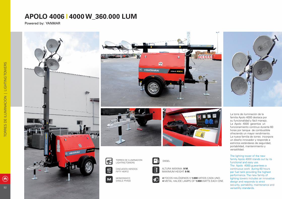
La torre de iluminación de la familia Apolo 4000 destaca por su funcionalidad y fácil manejo. La Apolo 4000 garantiza un funcionamiento continuo durante 60 horas por tanque de combustible ofreciendo un mayor rendimiento. La nueva familia de torres incorpora un diseño innovador y responde a estrictos estándares de seguridad, portabilidad, mantenimiento y versatilidad.
The lighting tower of the new family Apolo 4000 stands out by its functional and easy use.The Apolo 4000 guarantees a continuous work during 60 hours per fuel tank providing the highest performance. The new family of lighting towers includes an innovative design and responds to strict security, portability, maintenance and versatility standards.
TOR
RE
S D
E IL
UM
INA
CIO
N |
LIG
HTI
NG
TO
WE
RS
DIESEL
CINCUENTA HERZIOSFIFTY HERTZ
TORRES DE ILUMINACIONLIGHTING TOWERS
MONOFASICOSINGLE PHASE
4 FOCOS HALÓGENOS X 1.000 VATIOS CADA UNO. 4 METAL HALIDE LAMPS OF 1.000 WATTS EACH ONE.
ALTURA MÁXIMA: 9 M. MAXIMUM HEIGHT: 9 M.
APOLO 4006 4000 W_360.000 LUMPowered by: YANMAR
92
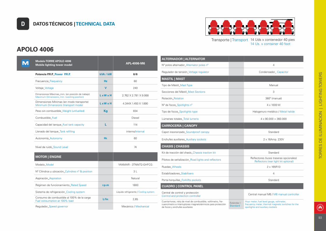
APOLO 4006
DATOS TÉCNICOS | TECHNICAL DATA D
TOR
RE
S D
E IL
UM
INA
CIO
N |
LIG
HTI
NG
TO
WE
RS
Transporte | Transport 14 Uds x contenedor 40 pies14 Us. x container 40 foot
Modelo TORRE APOLO 4006Mobile lighting tower model APL-4006-M6
Potencia P.R.P._Power P.R.P. kVA / kW 6/6
Frecuencia_Frequency Hz 60
Voltaje_Voltage V 240
Dimensiones Máximas_mm. (en posición de trabajo) Maximum Dimensions_mm. (working position)
L x W x H 2.762 X 2.781 X 9.068
Dimensiones Mínimas (en modo transporte)Minimum Dimensions (transport mode)
L x W x H 4.344X 1.450 X 1.890
Peso sin combustible_Weight (unfuelled) Kg 834
Combustible_Fuel Diesel
Capacidad del tanque_Fuel tank capacity L 114
Llenado del tanque_Tank refilling interno/internal
Autonomía_Autonomy Hr. 60
Nivel de ruido_Sound Level 74
MOTOR | ENGINE
Modelo_Model YANMAR - 3TNM72-GHFCG
Nº Cilindros y ubicación_Cylindres nº & position 3 L
Aspiración_Aspiration Natural
Régimen de funcionamiento_Rated Speed r.p.m 1800
Sistema de refrigeración_Cooling system Líquido refrigerante / Cooling system
Consumo de combustible al 100% de la cargaFuel consumption at 100% load
L/hr. 2,65
Regulador_Speed governor Mecánico / Mechanical
ALTERNADOR | ALTERNATOR
Nº polos alternador_Alternator poles nº 4
Regulador de tensión_Voltage regulator Condensador_ Capacitor
MASTIL | MAST
Tipo de Mástil_Mast Type Manual
Secciones del Mástil_Mast Sections 3
Rotación_Rotation 360º (manual)
Nº de focos_Spotlights nº 4 x 1000 W
Tipo de focos_Spotlights type Halogenuro metálico / Metal halide
Lúmenes totales_Total lumens 4 x 90.000 = 360.000
CARROCERÍA | CANOPY
Capot insonorizado_Soundproof canopy Standard
Enchufes auxiliares_Auxiliary sockets 2 x 16Amp. 230V
CHASIS | CHASSIS
Kit de tracción del chasis_Chassis traction kit Standard
Pilotos de señalización_Road lights and reflectors Reflectores (luces traseras opcionales) Reflectors (rear light kit optional)
Ruedas_Wheels 2 x 165R13
Estabilizadores_Stabilisers 4
Porta-horquillas_Forklifts pockets Standard
CUADRO | CONTROL PANEL
Central de control y protecciónControl and protection controller Central manual M6 / M6 manual controller
Cuenta-horas, reloj de nivel de combustible, voltímetro, fre-cuencímetro e interruptores magnetotérmicos para protección de focos y enchufes auxiliares
Estándar / Standard
Hour meter, fuel level gauge, voltmeter, frecuency meter, thermal magnetic switches for the spotlights and auxiliary sockets
93
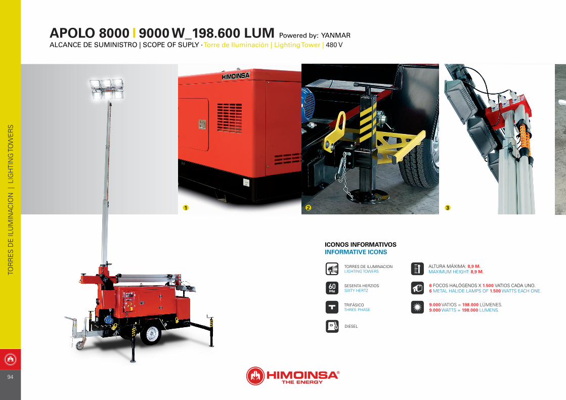
APOLO 8000 9000 W_198.600 LUM Powered by: YANMARALCANCE DE SUMINISTRO | SCOPE OF SUPLY · Torre de Iluminación | Lighting Tower | 480 V
1 2 3
ICONOS INFORMATIVOSINFORMATIVE ICONS
DIESEL
SESENTA HERZIOSSIXTY HERTZ
TORRES DE ILUMINACIONLIGHTING TOWERS
6 FOCOS HALÓGENOS X 1.500 VATIOS CADA UNO. 6 METAL HALIDE LAMPS OF 1.500 WATTS EACH ONE.
ALTURA MÁXIMA: 8,9 M. MAXIMUM HEIGHT: 8,9 M.
9.000 VATIOS = 198.000 LÚMENES. 9.000 WATTS = 198.000 LUMENS.
TOR
RE
S D
E IL
UM
INA
CIO
N |
LIG
HTI
NG
TO
WE
RS
TRIFÁSICOTHREE PHASE
94
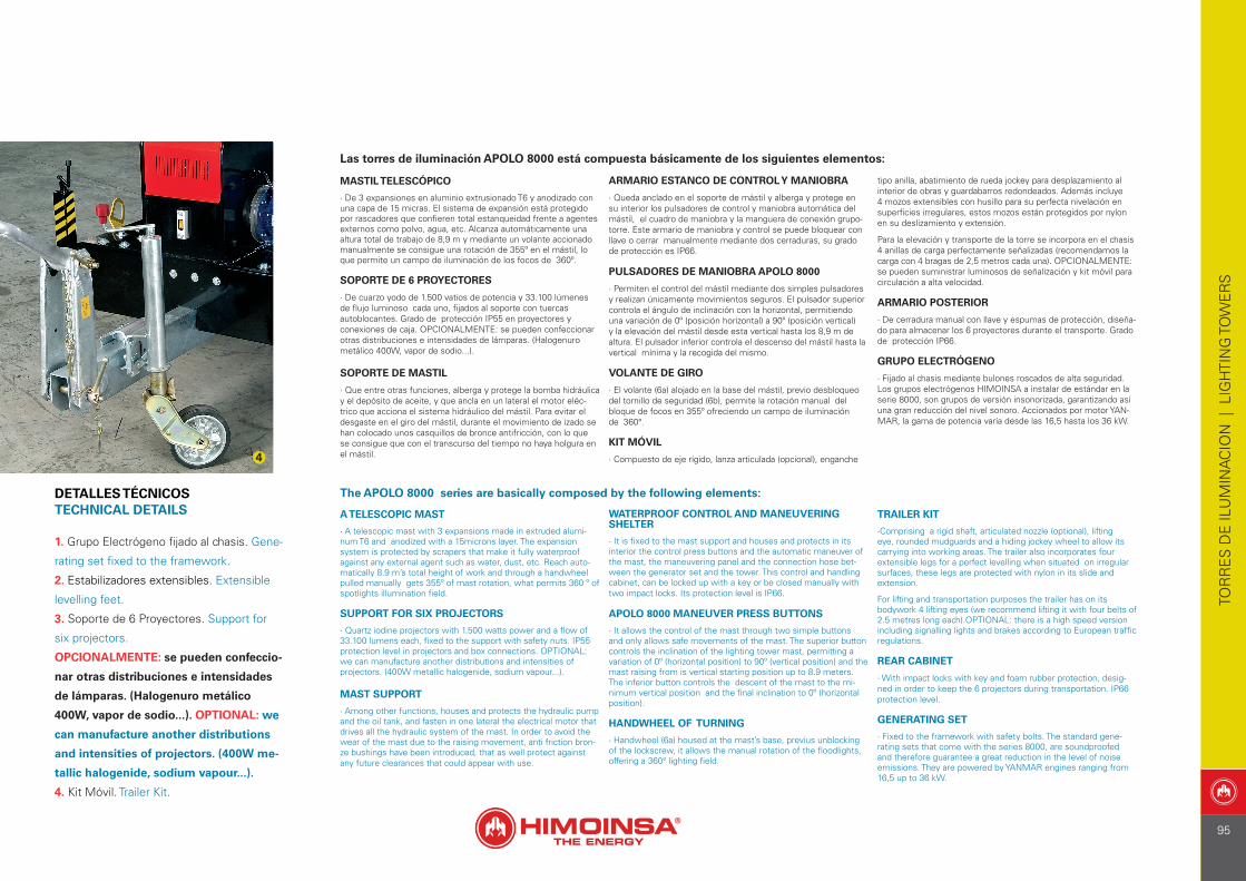
Las torres de iluminación APOLO 8000 está compuesta básicamente de los siguientes elementos:
MASTIL TELESCÓPICO
· De 3 expansiones en aluminio extrusionado T6 y anodizado con una capa de 15 micras. El sistema de expansión está protegido por rascadores que confieren total estanqueidad frente a agentes externos como polvo, agua, etc. Alcanza automáticamente una altura total de trabajo de 8,9 m y mediante un volante accionado manualmente se consigue una rotación de 355º en el mástil, lo que permite un campo de iluminación de los focos de 360º.
SOPORTE DE 6 PROYECTORES
· De cuarzo yodo de 1.500 vatios de potencia y 33.100 lúmenes de flujo luminoso cada uno, fijados al soporte con tuercas autoblocantes. Grado de protección IP55 en proyectores y conexiones de caja. OPCIONALMENTE: se pueden confeccionar otras distribuciones e intensidades de lámparas. (Halogenuro metálico 400W, vapor de sodio...).
SOPORTE DE MASTIL
· Que entre otras funciones, alberga y protege la bomba hidráulica y el depósito de aceite, y que ancla en un lateral el motor eléc-trico que acciona el sistema hidráulico del mástil. Para evitar el desgaste en el giro del mástil, durante el movimiento de izado se han colocado unos casquillos de bronce antifricción, con lo que se consigue que con el transcurso del tiempo no haya holgura en el mástil.
ARMARIO ESTANCO DE CONTROL Y MANIOBRA
· Queda anclado en el soporte de mástil y alberga y protege en su interior los pulsadores de control y maniobra automática del mástil, el cuadro de maniobra y la manguera de conexión grupo-torre. Este armario de maniobra y control se puede bloquear con llave o cerrar manualmente mediante dos cerraduras, su grado de protección es IP66.
PULSADORES DE MANIOBRA APOLO 8000
· Permiten el control del mástil mediante dos simples pulsadores y realizan únicamente movimientos seguros. El pulsador superior controla el ángulo de inclinación con la horizontal, permitiendo una variación de 0º (posición horizontal) a 90º (posición vertical) y la elevación del mástil desde esta vertical hasta los 8,9 m de altura. El pulsador inferior controla el descenso del mástil hasta la vertical mínima y la recogida del mismo.
VOLANTE DE GIRO
· El volante (6a) alojado en la base del mástil, previo desbloqueo del tornillo de seguridad (6b), permite la rotación manual del bloque de focos en 355º ofreciendo un campo de iluminación de 360°.
KIT MÓVIL
· Compuesto de eje rígido, lanza articulada (opcional), enganche
tipo anilla, abatimiento de rueda jockey para desplazamiento al interior de obras y guardabarros redondeados. Además incluye 4 mozos extensibles con husillo para su perfecta nivelación en superficies irregulares, estos mozos están protegidos por nylon en su deslizamiento y extensión.
Para la elevación y transporte de la torre se incorpora en el chasis 4 anillas de carga perfectamente señalizadas (recomendamos la carga con 4 bragas de 2,5 metros cada una). OPCIONALMENTE: se pueden suministrar luminosos de señalización y kit móvil para circulación a alta velocidad.
ARMARIO POSTERIOR
· De cerradura manual con llave y espumas de protección, diseña-do para almacenar los 6 proyectores durante el transporte. Grado de protección IP66.
GRUPO ELECTRÓGENO
· Fijado al chasis mediante bulones roscados de alta seguridad. Los grupos electrógenos HIMOINSA a instalar de estándar en la serie 8000, son grupos de versión insonorizada, garantizando así una gran reducción del nivel sonoro. Accionados por motor YAN-MAR, la gama de potencia varía desde las 16,5 hasta los 36 kW.
The APOLO 8000 series are basically composed by the following elements:
A TELESCOPIC MAST
· A telescopic mast with 3 expansions made in extruded alumi-num T6 and anodized with a 15microns layer. The expansion system is protected by scrapers that make it fully waterproof against any external agent such as water, dust, etc. Reach auto-matically 8.9 m’s total height of work and through a handwheel pulled manually gets 355º of mast rotation, what permits 360 º of spotlights illumination field.
SUPPORT FOR SIX PROJECTORS
· Quartz iodine projectors with 1.500 watts power and a flow of 33.100 lumens each, fixed to the support with safety nuts. IP55 protection level in projectors and box connections. OPTIONAL: we can manufacture another distributions and intensities of projectors. (400W metallic halogenide, sodium vapour...).
MAST SUPPORT
· Among other functions, houses and protects the hydraulic pump and the oil tank, and fasten in one lateral the electrical motor that drives all the hydraulic system of the mast. In order to avoid the wear of the mast due to the raising movement, anti friction bron-ze bushings have been introduced, that as well protect against any future clearances that could appear with use.
WATERPROOF CONTROL AND MANEUVERING SHELTER
· It is fixed to the mast support and houses and protects in its interior the control press buttons and the automatic maneuver of the mast, the maneuvering panel and the connection hose bet-ween the generator set and the tower. This control and handling cabinet, can be locked up with a key or be closed manually with two impact locks. Its protection level is IP66.
APOLO 8000 MANEUVER PRESS BUTTONS
· It allows the control of the mast through two simple buttons and only allows safe movements of the mast. The superior button controls the inclination of the lighting tower mast, permitting a variation of 0º (horizontal position) to 90º (vertical position) and the mast raising from is vertical starting position up to 8.9 meters. The inferior button controls the descent of the mast to the mi-nimum vertical position and the final inclination to 0º (horizontal position).
HANDWHEEL OF TURNING
· Handwheel (6a) housed at the mast’s base, previus unblocking of the lockscrew, it allows the manual rotation of the floodlights, offering a 360° lighting field.
TRAILER KIT
·Comprising a rigid shaft, articulated nozzle (optional), lifting eye, rounded mudguards and a hiding jockey wheel to allow its carrying into working areas. The trailer also incorporates four extensible legs for a perfect levelling when situated on irregular surfaces, these legs are protected with nylon in its slide and extension.
For lifting and transportation purposes the trailer has on its bodywork 4 lifting eyes (we recommend lifting it with four belts of 2.5 metres long each).OPTIONAL: there is a high speed version including signalling lights and brakes according to European traffic regulations.
REAR CABINET
· With impact locks with key and foam rubber protection, desig-ned in order to keep the 6 projectors during transportation. IP66 protection level.
GENERATING SET
· Fixed to the framework with safety bolts. The standard gene-rating sets that come with the series 8000, are soundproofed and therefore guarantee a great reduction in the level of noise emissions. They are powered by YANMAR engines ranging from 16,5 up to 36 kW.
1. Grupo Electrógeno fijado al chasis. Gene-
rating set fixed to the framework.
2. Estabilizadores extensibles. Extensible
levelling feet.
3. Soporte de 6 Proyectores. Support for
six projectors.
OPCIONALMENTE: se pueden confeccio-
nar otras distribuciones e intensidades
de lámparas. (Halogenuro metálico
400W, vapor de sodio...). OPTIONAL: we
can manufacture another distributions
and intensities of projectors. (400W me-
tallic halogenide, sodium vapour...).
4. Kit Móvil. Trailer Kit.
DETALLES TÉCNICOS TECHNICAL DETAILS
4
TOR
RE
S D
E IL
UM
INA
CIO
N |
LIG
HTI
NG
TO
WE
RS
95
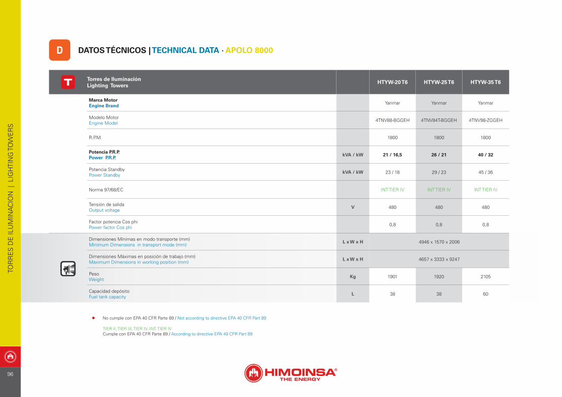
Torres de IluminaciónLighting Towers
HTYW-20 T6 HTYW-25 T6 HTYW-35 T6
Marca MotorEngine Brand Yanmar Yanmar Yanmar
Modelo Motor Engine Model 4TNV88-BGGEH 4TNV84T-BGGEH 4TNV98-ZGGEH
R.P.M. 1800 1800 1800
Potencia P.R.P. Power P.R.P.
kVA / kW 21 / 16,5 26 / 21 40 / 32
Potencia StandbyPower Standby
kVA / kW 23 / 18 29 / 23 45 / 36
Norma 97/68/EC INT TIER IV INT TIER IV INT TIER IV
Tensión de salida Output voltage
V 480 480 480
Factor potencia Cos phiPower factor Cos phi 0,8 0,8 0,8
Dimensiones Mínimas en modo transporte (mm)Minimum Dimensions in transport mode (mm)
L x W x H 4946 x 1570 x 2006
Dimensiones Máximas en posición de trabajo (mm)Maximum Dimensions in working position (mm)
L x W x H 4657 x 3333 x 9247
PesoWeight
Kg 1901 1920 2105
Capacidad depósitoFuel tank capacity
L 38 38 60
DATOS TÉCNICOS | TECHNICAL DATA · APOLO 8000D
TOR
RE
S D
E IL
UM
INA
CIO
N |
LIG
HTI
NG
TO
WE
RS
• No cumple con EPA 40 CFR Parte 89 / Not according to directive EPA 40 CFR Part 89
TIER II, TIER III, TIER IV, INT. TIER IVCumple con EPA 40 CFR Parte 89 / According to directive EPA 40 CFR Part 89
96

CUADROS DE CONTROL Y POTENCIACONTROL AND POWER PANELS:
GAMA PROFESIONAL_PROFESSIONAL RANGE
CU
AD
RO
S Y
CE
NTR
ALE
S |
CO
NTR
OL
& P
OW
ER
PA
NE
LS
97
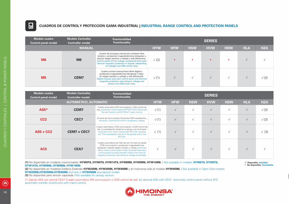
Modelo cuadro
Control panel model
Modelo Centralita
Controller modelFuncionalidad Functionality SERIES
MANUAL HYW HFW HSW HVW HDW HLA HZA
M6 M6
Cuadro de arranque manual por contacto libre tensión y protección magnetotérmica tetrapolar o bipolar (según tensión y voltaje) y relé diferencial_ Control panel of free voltage contactand tetra polar thermal magnetic protection or bipolar (depending
on voltage) and diffe-rential relay.
√ (2) • • • • √ √
M5 CEM7
Cuadro control manual Auto-Start digital y protección magnetotérmica tetrapolar o bipo-lar (según tensión y voltaje) y relé diferencial_
Digital manual auto-start control panel and thermal magnetic protection (according to voltage and
phase) and differential relay.
√ (1) √ √ √ √ √ √ (3)
Modelo cuadro
Control panel model
Modelo Centralita
Controller modelFuncionalidad Functionality SERIES
AUTOMÁTICO_AUTOMATIC HYW HFW HSW HVW HDW HLA HZA
AS5* CEM7Cuadro automático SIN conmutación y SIN control de
red_ Automatic control panel WITHOUT ATS (Automatic Transfer Switch) and WITHOUT mains control.
√ (1) √ √ √ √ √ √ (3)
CC2 CEC7 Armario de Conmutación Himoinsa CON visualización_Himoinsa External ATS WiITH visualization display. √ (1) √ √ √ √ √ √ (3)
AS5 + CC2 CEM7 + CEC7
Cuadro automático CON conmutación y CON control de red. La visualización estará en el grupo y en el armario. Automatic with mains control and ATS with visualiza-tion. The visualization will be in the genset and in the
ATS box.
√ (1) √ √ √ √ √ √ (3)
AC5 CEA7
Cuadro automático por fallo de red. Armario en pared CON conmutación y protección magnetotérmica
tetrapolar o bipolar (según tensión y voltaje_Automatic Mains Failure control panel. Wall mounted Automatic control panel including transfer switch with thermal
magnetic protection (according to voltage and phase).
√ √ √ √ √ √ √
CUADROS DE CONTROL Y PROTECCIÓN GAMA INDUSTRIAL | INDUSTRIAL RANGE CONTROL AND PROTECTION PANELS
(1) No disponible en modelos insonorizados: HYW6T6, HYW9T6, HYW14T6, HYW6M6, HYW9M6, HYW14M6. / Not available in models: HYW6T6, HYW9T6, HYW14T6, HYW6M6, HYW9M6, HYW14M6.(2) No disponible en modelos Estático Estándar HYW25M6, HYW35M6, HYW45M6 y en Insonoros solo el modelo HYW45M6. / Not available in Open Skid models: HYW25M6,HYW35M6,HYW45M6 and only in HYW45M6 soundproof model.(3) No disponible para versión capotada / Not available for canopy version.
(*) Opción AS5 con central CEA7. Cuadro automático SIN conmutación y CON control de red. As optional AS5 with CEA7 Automatic control panel without ATS(automatic transfer switch) and with mains control.
√ Disponible_Available• No disponible_Unavailable
CU
AD
RO
S Y
CE
NTR
ALE
S |
CO
NTR
OL
& P
OW
ER
PA
NE
LS
98

G.E. ESTÁTICO ESTÁNDAR_OPEN SKID G.S. G.E. INSONORIZADO_SOUNDPROOF G.S.
M5
A) <125A
*K1,K2,K3,K4
B) 125A a 250A
*K3,K4, K6
C) >250A
*K4, K6, K7, K8, K9, K18, K19 *B10, C10, D10 *E10, F1, G1, H1, J
A) <125A C) >250A
*B10, C10, D10, E10
B) 125A a 250A
MODELOS CUADRO MANUALES MANUAL CONTROL PANEL MODELS
* Versión Constructiva_Constructive Version
M6
HLA, HZA, HYW HZA HYW (*A10) HYW, (*B10)
CU
AD
RO
S Y
CE
NTR
ALE
S |
CO
NTR
OL
& P
OW
ER
PA
NE
LS
99
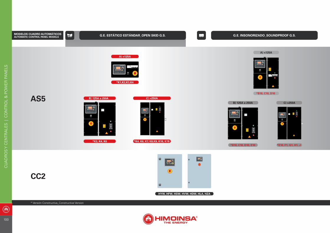
G.E. ESTÁTICO ESTÁNDAR_OPEN SKID G.S. G.E. INSONORIZADO_SOUNDPROOF G.S.
AS5
CC2
A) <125A
*K1,K2,K3,K4
HYW, HFW, HSW, HVW, HDW, HLA, HZA
* Versión Constructiva_Constructive Version
MODELOS CUADRO AUTOMÁTICOS AUTOMATIC CONTROL PANEL MODELS
*B10, C10, D10
A) <125A
*B10, C10, D10, E10
B) 125A a 250A
*E10, F1, G1, H1, J
C) >250A
*K3, K4, K6
B) 125A a 250A
*K4, K6, K7, K8,K9, K18, K19
C) >250A
CU
AD
RO
S Y
CE
NTR
ALE
S |
CO
NTR
OL
& P
OW
ER
PA
NE
LS
100

G.E. ESTÁTICO ESTÁNDAR_OPEN SKID G.S. G.E. INSONORIZADO_SOUNDPROOF G.S.
* Versión Constructiva_Constructive Version
AS5 + CC2
*K4, K6, K7, K8, K9, K18, K19
C) >250A
AC5HYW, HFW, HSW, HVW, HDW, HLA, HZA
+ +
*K1,K2,K3,K4
B) 125A a 250A
*K3, K4, K6
+
A) <125A
+
+
*B10, C10, D10
A) <125A
C) >250AB) 125A a 250A
*E10, F1, G1, H1, J*B10, C10, D10, E10
MODELOS CUADRO AUTOMÁTICOS AUTOMATIC CONTROL PANEL MODELS
+
CU
AD
RO
S Y
CE
NTR
ALE
S |
CO
NTR
OL
& P
OW
ER
PA
NE
LS
101
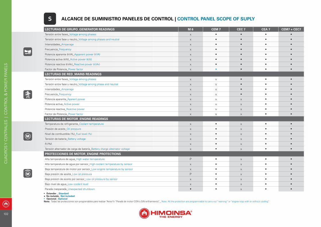
LECTURAS DE GRUPO_GENERATOR READINGS M 6 CEM 7 CEC 7 CEA 7 CEM7 + CEC7
Tensión entre fases_Voltage among phases x • • • •
Tensión entre fase y neutro_Voltage among phases and neutral x • • • •
Intensidades_Amperage x • • • •
Frecuencia_Frequency x • • • •
Potencia aparente (kVA)_Apparent power (kVA) x • • • •
Potencia activa (kW)_Active power (kW) x • • • •
Potencia reactiva (kVAr)_Reactive power (kVAr) x • • • •
Factor de Potencia_Power factor x • • • •
LECTURAS DE RED_MAINS READINGS
Tensión entre fases_Voltage among phases x x • • •
Tensión entre fase y neutro_Voltage among phase and neutral x x • • •
Intensidades_Amperage x x • • •
Frecuencia_Frequency x x • • •
Potencia aparente_Aparent power x x x • •
Potencia activa_Active power x x x • •
Potencia reactiva_Reactive power x x x • •
Factor de Potencia_Power factor x x x • •
LECTURAS DE MOTOR_ENGINE READINGS
Temperatura de refrigerante_Coolant temperature x • x • •
Presión de aceite_Oil pressure x • x • •
Nivel de combustible (%)_Fuel level (%) x • x • •
Tensión de batería_Battery voltage x • x • •
R.P.M. x • x • •
Tensión alternador de carga de batería_Battery charge alternator voltage x • x • •
PROTECCIONES DE MOTOR_ENGINE PROTECTIONS
Alta temperatura de agua_High water temperature P • x • •
Alta temperatura de agua por sensor_High coolant temperature by sensor x • x • •
Baja temperatura de motor por sensor_Low engine temperature by sensor x • x • •
Baja presión de aceite_Low oil pressure P • x • •
Baja presión de aceite por sensor_Low oil pressure by sensor x • x • •
Bajo nivel de agua_Low coolant level x • x • •
Parada inesperada_Unexpected shutdown • • x • •
S ALCANCE DE SUMINISTRO PANELES DE CONTROL | CONTROL PANEL SCOPE OF SUPLY
• Estandar _ Standardx No incluido_ Not included• Opcional_ OptionalNota: Todas las protecciones son programables para realizar “Aviso”o “Parada de motor CON o SIN enfriamiento”. _ Note: All the protection are programmable to carry out “warning” or “engine stop with or without cooling”.
CU
AD
RO
S Y
CE
NTR
ALE
S |
CO
NTR
OL
& P
OW
ER
PA
NE
LS
102
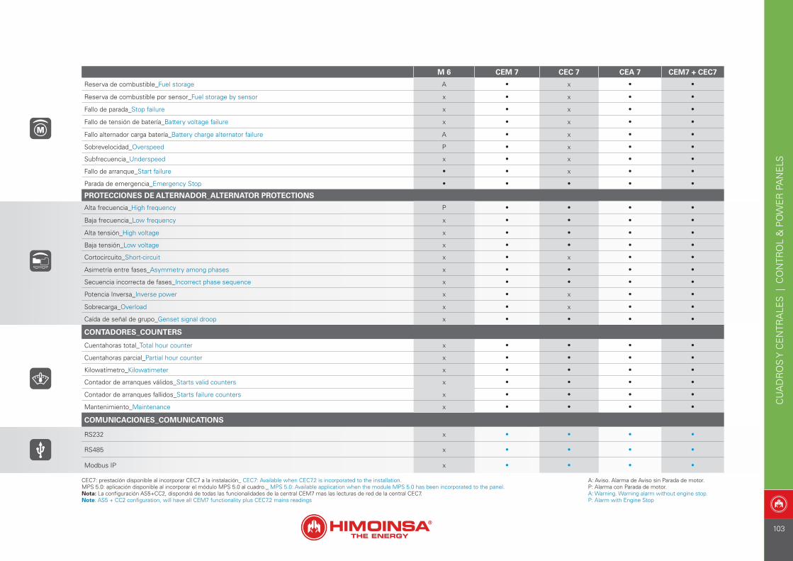
M 6 CEM 7 CEC 7 CEA 7 CEM7 + CEC7
Reserva de combustible_Fuel storage A • x • •
Reserva de combustible por sensor_Fuel storage by sensor x • x • •
Fallo de parada_Stop failure x • x • •
Fallo de tensión de batería_Battery voltage failure x • x • •
Fallo alternador carga batería_Battery charge alternator failure A • x • •
Sobrevelocidad_Overspeed P • x • •
Subfrecuencia_Underspeed x • x • •
Fallo de arranque_Start failure • • x • •
Parada de emergencia_Emergency Stop • • • • •
PROTECCIONES DE ALTERNADOR_ALTERNATOR PROTECTIONS
Alta frecuencia_High frequency P • • • •
Baja frecuencia_Low frequency x • • • •
Alta tensión_High voltage x • • • •
Baja tensión_Low voltage x • • • •
Cortocircuito_Short-circuit x • x • •
Asimetría entre fases_Asymmetry among phases x • • • •
Secuencia incorrecta de fases_Incorrect phase sequence x • • • •
Potencia Inversa_Inverse power x • x • •
Sobrecarga_Overload x • x • •
Caída de señal de grupo_Genset signal droop x • • • •
CONTADORES_COUNTERS
Cuentahoras total_Total hour counter x • • • •
Cuentahoras parcial_Partial hour counter x • • • •
Kilowatímetro_Kilowatimeter x • • • •
Contador de arranques válidos_Starts valid counters x • • • •
Contador de arranques fallidos_Starts failure counters x • • • •
Mantenimiento_Maintenance x • • • •
COMUNICACIONES_COMUNICATIONS
RS232 x • • • •
RS485 x • • • •
Modbus IP x • • • •
A: Aviso. Alarma de Aviso sin Parada de motor.P: Alarma con Parada de motor.A: Warning. Warning alarm without engine stop.P: Alarm with Engine Stop
CEC7: prestación disponible al incorporar CEC7 a la instalación_ CEC7: Available when CEC7.2 is incorporated to the installation.MPS 5.0: aplicación disponible al incorporar el módulo MPS 5.0 al cuadro._ MPS 5.0: Available application when the module MPS 5.0 has been incorporated to the panel.Nota: La configuración AS5+CC2, dispondrá de todas las funcionalidades de la central CEM7 mas las lecturas de red de la central CEC7.Note: AS5 + CC2 configuration, will have all CEM7 functionality plus CEC7.2 mains readings
CU
AD
RO
S Y
CE
NTR
ALE
S |
CO
NTR
OL
& P
OW
ER
PA
NE
LS
103
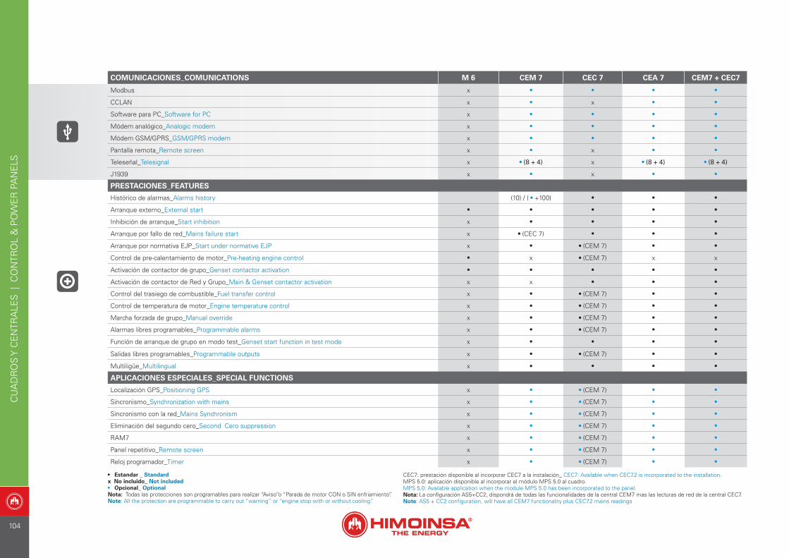
COMUNICACIONES_COMUNICATIONS M 6 CEM 7 CEC 7 CEA 7 CEM7 + CEC7
Modbus x • • • •
CCLAN x • x • •
Software para PC_Software for PC x • • • •
Módem analógico_Analogic modem x • • • •
Módem GSM/GPRS_GSM/GPRS modem x • • • •
Pantalla remota_Remote screen x • x • •
Teleseñal_Telesignal x • (8 + 4) x • (8 + 4) • (8 + 4)
J1939 x • x • •
PRESTACIONES_FEATURES
Histórico de alarmas_Alarms history (10) / ( • +100) • • •
Arranque externo_External start • • • • •
Inhibición de arranque_Start inhibition x • • • •
Arranque por fallo de red_Mains failure start x • (CEC 7) • • •
Arranque por normativa EJP_Start under normative EJP x • • (CEM 7) • •
Control de pre-calentamiento de motor_Pre-heating engine control • x • (CEM 7) x x
Activación de contactor de grupo_Genset contactor activation • • • • •
Activación de contactor de Red y Grupo_Main & Genset contactor activation x x • • •
Control del trasiego de combustible_Fuel transfer control x • • (CEM 7) • •
Control de temperatura de motor_Engine temperature control x • • (CEM 7) • •
Marcha forzada de grupo_Manual override x • • (CEM 7) • •
Alarmas libres programables_Programmable alarms x • • (CEM 7) • •
Función de arranque de grupo en modo test_Genset start function in test mode x • • • •
Salidas libres programables_Programmable outputs x • • (CEM 7) • •
Multiligüe_Multilingual x • • • •
APLICACIONES ESPECIALES_SPECIAL FUNCTIONS
Localización GPS_Positioning GPS x • • (CEM 7) • •
Sincronismo_Synchronization with mains x • • (CEM 7) • •
Sincronismo con la red_Mains Synchronism x • • (CEM 7) • •
Eliminación del segundo cero_Second Cero suppression x • • (CEM 7) • •
RAM7 x • • (CEM 7) • •
Panel repetitivo_Remote screen x • • (CEM 7) • •
Reloj programador_Timer x • • (CEM 7) • •
• Estandar _ Standardx No incluido_ Not included• Opcional_ OptionalNota: Todas las protecciones son programables para realizar “Aviso”o “Parada de motor CON o SIN enfriamiento”.Note: All the protection are programmable to carry out “warning” or “engine stop with or without cooling”.
CEC7: prestación disponible al incorporar CEC7 a la instalación_ CEC7: Available when CEC7.2 is incorporated to the installation.MPS 5.0: aplicación disponible al incorporar el módulo MPS 5.0 al cuadro.MPS 5.0: Available application when the module MPS 5.0 has been incorporated to the panel.Nota: La configuración AS5+CC2, dispondrá de todas las funcionalidades de la central CEM7 mas las lecturas de red de la central CEC7.Note: AS5 + CC2 configuration, will have all CEM7 functionality plus CEC7.2 mains readings
CU
AD
RO
S Y
CE
NTR
ALE
S |
CO
NTR
OL
& P
OW
ER
PA
NE
LS
104
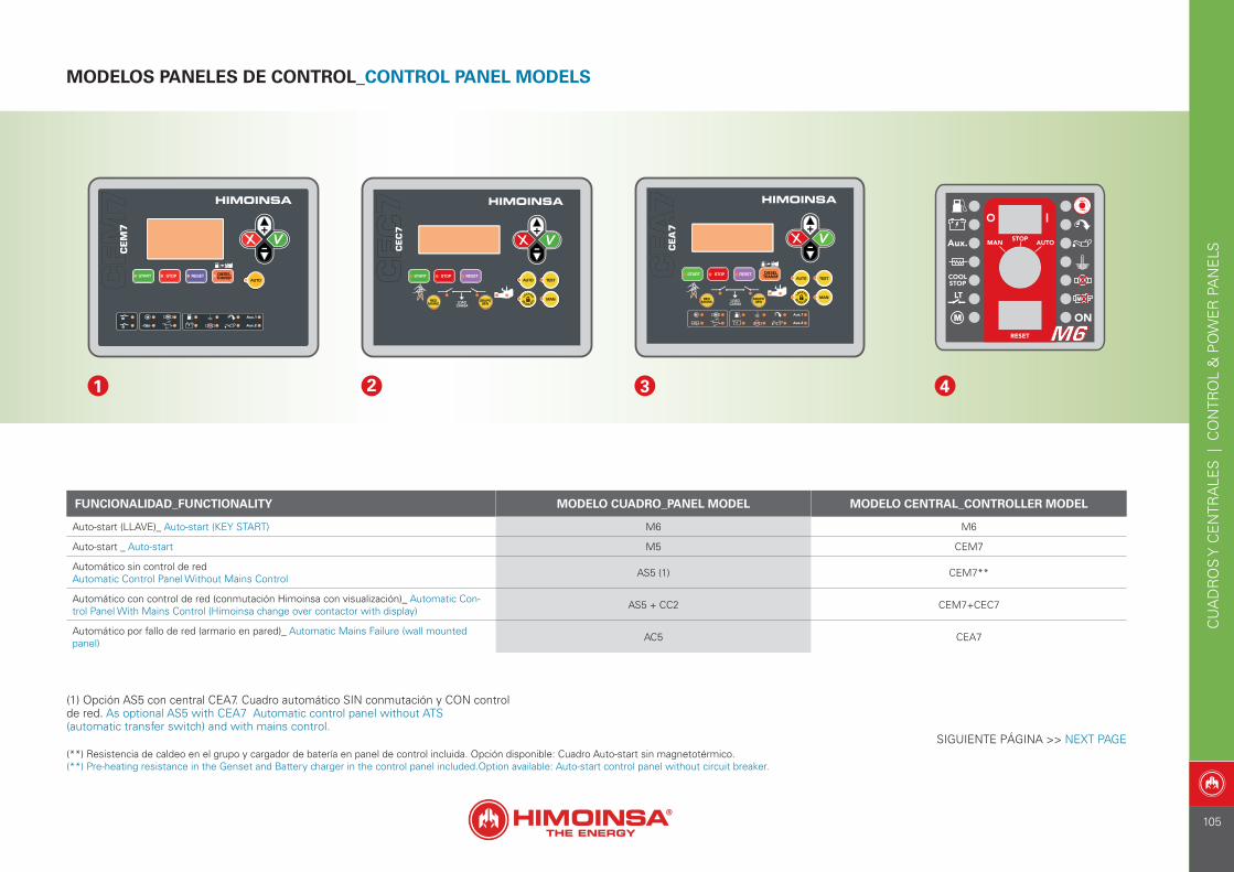
MODELOS PANELES DE CONTROL_CONTROL PANEL MODELS
(**) Resistencia de caldeo en el grupo y cargador de batería en panel de control incluida. Opción disponible: Cuadro Auto-start sin magnetotérmico.(**) Pre-heating resistance in the Genset and Battery charger in the control panel included.Option available: Auto-start control panel without circuit breaker.
FUNCIONALIDAD_FUNCTIONALITY MODELO CUADRO_PANEL MODEL MODELO CENTRAL_CONTROLLER MODEL
Auto-start (LLAVE)_ Auto-start (KEY START) M6 M6
Auto-start _ Auto-start M5 CEM7
Automático sin control de redAutomatic Control Panel Without Mains Control AS5 (1) CEM7**
Automático con control de red (conmutación Himoinsa con visualización)_ Automatic Con-trol Panel With Mains Control (Himoinsa change over contactor with display) AS5 + CC2 CEM7+CEC7
Automático por fallo de red (armario en pared)_ Automatic Mains Failure (wall mounted panel) AC5 CEA7
1 2 3 4
SIGUIENTE PÁGINA >> NEXT PAGE
(1) Opción AS5 con central CEA7. Cuadro automático SIN conmutación y CON control de red. As optional AS5 with CEA7 Automatic control panel without ATS(automatic transfer switch) and with mains control.
CU
AD
RO
S Y
CE
NTR
ALE
S |
CO
NTR
OL
& P
OW
ER
PA
NE
LS
105
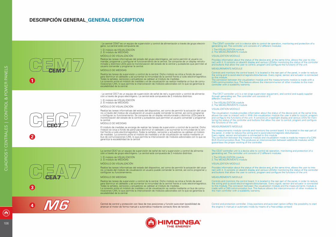
DESCRIPCIÓN GENERAL_GENERAL DESCRIPTION
3
4
· La central CEM7 es un equipo de supervisión y control de alimentación a través de grupo electró-geno. La central está compuesta de:
1. El módulo de VISUALIZACIÓN2. El módulo de MEDIDASMÓDULO DE VISUALIZACIÓNRealiza las tareas informativas del estado del grupo electrógeno, así como permitir al usuario co-mandar, programar y configurar el funcionamiento de la central. Se compone de un display retroilu-minado y distintos LEDs para la monitorización del estado de la central y pulsadores que permiten al usuario comandar y programar la central.
MÓDULO DE MEDIDAS
Realiza las tareas de supervisión y control de la central. Dicho módulo se sitúa a fondo de panel para disminuir el cableado y así aumentar la inmunidad de la central frente a ruido electromagnético.Todas la señales, sensores y actuadores se cablean al módulo de medidas.La conexión entre el módulo de medidas y el de visualización se realiza mediante un bus de comu-nicaciones CAN, lo que permite la interconexión de módulos adicionales con lo que se garantiza la escalabilidad de la central.
· The CEM7 controller unit is a device able to control de operation, monitoring and protection of a generating set. The controller unit consists of 2 different modules:1. The VISUALIZATION module2. The MEASUREMENTS module
VISUALIZATION MODULE
Provides information about the status of the device and, at the same time, allows the user to inte-ract with it. It consists on abacklit display and various LEDsfor monitoring the status of the controller and buttons that allow the user to control, program and configure the functions of the unit.
MEASUREMENTS MODULE
Controls and monitors the control board. It is located in the rear part of the panel, in order to reduce the wiring and to avoid electromagneticdisturbances. Every signal, sensor and actuator is connected to this module.The connexion between the visualization module and the measurements module is made with a CAN communication bus. This feature allows the intercommunion of other modules to the main controller with a scalability warranty.
1
2
· La central CEC7 es un equipo de supervisión de señal de red y supervisión y control de alimenta-ción a través de grupo electrógeno. La central está compuesta de 2 módulos distintos:
1. El módulo de VISUALIZACIÓN2. El módulo de MEDIDAS
MÓDULO DE VISUALIZACIÓN
Realiza las tareas informativas del estado del dispositivo, así como de permitir la actuación del usua-rio; a través del móduo de visualización el usuario puede comandar la central, así como programar y configurar su funcionamiento. Se compone de un display retroiluminado y distintos LEDs para la monitorización del estado de la central y pulsadores que permiten al usuario comandar y programar la central.MÓDULO DE MEDIDAS
El módulo de medidas se encarga de realizar las tareas de supervisión y control de la central. Dicho módulo se sitúa a fondo de panel para disminuir el cableado y así aumentar la inmunidad de la cen-tral frente a ruido electromagnético. Todas la señales, sensores y actuadores se cablean al módulode medidas. La conexión entre el módulo de medidas y el de visualización se realiza mediante un bus de comunicaciones CAN, lo que permite la interconexión de módulos adicionales con lo que se garantiza la escalabilidad de la central
· The CEC7 controller unit is a net sings supervision equipment, and control and supply supplier through generating set. The controller unit consists of 2different modules:
1. The VISUALIZATION module2. The MEASUREMENTS module
VISUALIZATION MODULE
The visualization module provides information about the status of the device and, at the same time, allows the user to interact with it. With this visualization module the user is able to control, program and configure the functions of the unit. It consists on a backlight display and various LEDs for moni-toring the status of the controller and buttons that allow the user to control, program and configure the functions of the unit.
MEASUREMENTS MODULE
The measurements module controls and monitors the control board. It is located in the rear part of the panel, in order to reduce the wiring and to avoid electromagnetic disturbances.Every signal, sensor and actuator is connected to this moduleThe connection between the measure module and visualization mode is made by means of a CAN BUS (Communication Bus). This produces an interconnection between additional modules which guarantees the proper working of the controller.
La central CEA7 es un equipo de supervisión de señal de red y supervisión y control de alimenta-ción a través de grupo electrógeno. La central está compuesta de 2 módulos distintos:
1. El módulo de VISUALIZACIÓN2. El módulo de MEDIDAS
MÓDULO DE VISUALIZACIÓN
Realiza las tareas informativas del estado del dispositivo, así como de permitir la actuación del usua-rio; a través del módulo de visualización el usuario puede comandar la central, así como programar y configurar su funcionamiento.
MÓDULO DE MEDIDAS
Realiza las tareas de supervisión y control de la central. Dicho módulo se sitúa a fondo de panel para disminuir el cableado y así aumentar la inmunidad de la central frente a ruido electromagnético. Todas la señales, sensores y actuadores se cablean al módulo de medidas.La conexión entre el módulo de medidas y el de visualización se realiza mediante un bus de comu-nicaciones CAN, lo que permite la interconexión de módulos adicionales con lo que se garantiza la escalabilidad de la central.
The CEA7 controller unit is a device able to control de operation, monitoring and protection of a generating set. The controller unit consists of 2 different modules:
1. The VISUALIZATION module2. The MEASUREMENTS module
VISUALIZATION MODULE
Provides information about the status of the device and, at the same time, allows the user to inte-ract with it. It consists on abacklit display and various LEDsfor monitoring the status of the controller and buttons that allow the user to control, program and configure the functions of the unit.
MEASUREMENTS MODULE
Controls and monitors the control board. It is located in the rear part of the panel, in order to reduce the wiring and to avoid electromagneticdisturbances. Every signal, sensor and actuator is connected to this module. The connexion between the visualization module and the measurements module is made with a CAN communication bus. This feature allows the intercommunion of other modules to the main controller with a scalability warranty.
Central de control y protección con llave de tres posiciones y función auto-start (posibilidad de arrancar el motor de forma manual o automática mediante contacto libre de tensión.
Control and protection controller. 3 key positions and auto-start option (offers the possibility to start the engine in manual or automatic mode by means of a free-voltaje contact)
CU
AD
RO
S Y
CE
NTR
ALE
S |
CO
NTR
OL
& P
OW
ER
PA
NE
LS
106
OP
OPCIONALES_OPTIONALS: GAMA INDUSTRIAL_INDUSTRIAL RANGE
GAMA RENTAL_RENTAL RANGE
OP
CIO
NA
LES
| O
PTI
ON
ALS
107
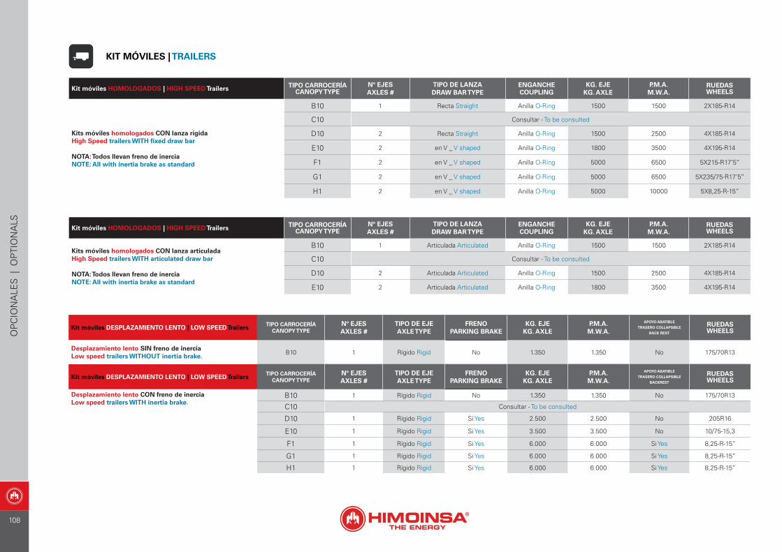
Kit móviles DESPLAZAMIENTO LENTO | LOW SPEED Trailers TIPO CARROCERÍACANOPY TYPE
Nº EJESAXLES #
TIPO DE EJEAXLE TYPE
FRENOPARKING BRAKE
KG. EJEKG. AXLE
P.M.A.M.W.A.
APOYO ABATIBLE
TRASERO COLLAPSIBLE
BACK REST
RUEDASWHEELS
Desplazamiento lento SIN freno de inerciaLow speed trailers WITHOUT inertia brake. B10 1 Rígido Rigid No 1.350 1.350 No 175/70R13
Kit móviles DESPLAZAMIENTO LENTO | LOW SPEED Trailers TIPO CARROCERÍACANOPY TYPE
Nº EJESAXLES #
TIPO DE EJEAXLE TYPE
FRENOPARKING BRAKE
KG. EJEKG. AXLE
P.M.A.M.W.A.
APOYO ABATIBLE
TRASERO COLLAPSIBLE
BACKREST
RUEDASWHEELS
Desplazamiento lento CON freno de inerciaLow speed trailers WITH inertia brake.
B10 1 Rígido Rigid No 1.350 1.350 No 175/70R13
C10 Consultar - To be consulted
D10 1 Rígido Rigid Si Yes 2.500 2.500 No 205R16
E10 1 Rígido Rigid Si Yes 3.500 3.500 No 10/75-15,3
F1 1 Rígido Rigid Si Yes 6.000 6.000 Si Yes 8,25-R-15’’
G1 1 Rígido Rigid Si Yes 6.000 6.000 Si Yes 8,25-R-15’’
H1 1 Rígido Rigid Si Yes 6.000 6.000 Si Yes 8,25-R-15’’
Kit móviles HOMOLOGADOS | HIGH SPEED Trailers TIPO CARROCERÍACANOPY TYPE
Nº EJESAXLES #
TIPO DE LANZADRAW BAR TYPE
ENGANCHECOUPLING
KG. EJEKG. AXLE
P.M.A.M.W.A.
RUEDASWHEELS
Kits móviles homologados CON lanza rígidaHigh Speed trailers WITH fixed draw bar
NOTA: Todos llevan freno de inerciaNOTE: All with inertia brake as standard
B10 1 Recta Straight Anilla O-Ring 1500 1500 2X185-R14
C10 Consultar - To be consulted
D10 2 Recta Straight Anilla O-Ring 1500 2500 4X185-R14
E10 2 en V _ V shaped Anilla O-Ring 1800 3500 4X195-R14
F1 2 en V _ V shaped Anilla O-Ring 5000 6500 5X215-R17’5’’
G1 2 en V _ V shaped Anilla O-Ring 5000 6500 5X235/75-R17’5’’
H1 2 en V _ V shaped Anilla O-Ring 5000 10000 5X8,25-R-15’’
Kit móviles HOMOLOGADOS | HIGH SPEED Trailers TIPO CARROCERÍACANOPY TYPE
Nº EJESAXLES #
TIPO DE LANZADRAW BAR TYPE
ENGANCHECOUPLING
KG. EJEKG. AXLE
P.M.A.M.W.A.
RUEDASWHEELS
Kits móviles homologados CON lanza articuladaHigh Speed trailers WITH articulated draw bar
NOTA: Todos llevan freno de inerciaNOTE: All with inertia brake as standard
B10 1 Articulada Articulated Anilla O-Ring 1500 1500 2X185-R14
C10 Consultar - To be consulted
D10 2 Articulada Articulated Anilla O-Ring 1500 2500 4X185-R14
E10 2 Articulada Articulated Anilla O-Ring 1800 3500 4X195-R14
KIT MÓVILES | TRAILERS
OP
CIO
NA
LES
| O
PTI
ON
ALS
108
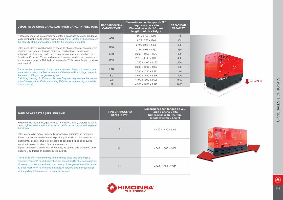
OP
CIO
NA
LES
| O
PTI
ON
ALS
DEPÓSITO DE GRAN CAPACIDAD | HIGH CAPACITY FUEL TANKTIPO CARROCERÍACANOPY TYPE
Dimensiones con tanque de G.C.largo x ancho x alto
Dimensions with H.C. tanklength x width x height
CAPACIDAD L CAPACITY L
• Depósito metálico que permite aumentar la capacidad estándar del depósi-to de combustible de la versión insonorizada_Metal fuel tank which increases the capacity of the standard fuel tank for the soundproof models.
Estos depósitos están fabricados en chapa de alta resistencia, con refuerzos interiores que evitan el traslado rápido del combustible y su derrame, sobretodo en el caso del izado del grupo electrógeno.Incorporan boca de llenado metálica de 120mm de diámetro. Están preparados para garantizar el suministro del grupo al 100 % de la carga entre 20-24 horas. (según modelos y consumos)
These fuel tanks are made of high resistance steel plates, with interior rein-forcements to avoid the fast movement of the fuel and its spillage, mainly in the event of lifting of the generating set.Fuel filling opening of 120mm of diameter.Prepared to guarantee the fuel su-pply of the genset at 100% load during 20-24 hours. (depending on models consumptions).
A101475 x 750 x 1208 40
1475 x 750 x 1264 100
B102.100 x 975 x 1.409 190
2.100 x 975 x 1.562 330
C10 2.300 x 1.050 x 1.573 400
D102.750 x 1.100 x 1.903 450
2.750 x 1.100 x 2.163 850
E103.300 x 1.200 x 1.958 600
3.300 x 1.200 x 2.171 1100
F1 3.800 x 1.400 x 2.615 999
G1 4.100 x 1.600 x 2.600 1660
H1 4.500 x 1.800 x 2.740 2090
PATÍN DE ARRASTRE | PULLING SKIDTIPO CARROCERÍA
CANOPY TYPE
Dimensiones con tanque de G.C.largo x ancho x alto
Dimensions with H.C. tanklength x width x height
• Patín de alta resistencia, que permite reforzar el chasis y proteger la carro-cería_High resistance skid, that allows to reinforce the chassis and to protect the canopy.
Estos patines dan mayor rigidez a la carrocería al garantizar un momento flector muy por encima del ofrecido por los patines de suministro estándar. Igualmente, alejan el grupo electrógeno de posibles golpes de pequeña maquinaria, protegiendo el chasis y la carrocería.El patín de arrastre como indica su nombre, es óptimo para el arrastre de la máquina y su trabajo en superficies irregulares.
These skids offer more stiffness to the canopy since they guarantee a “bending moment” much higher than the one offered by the standard skids. Moreover, it protects the chassis and canopy of the genset from hits caused by small machinery. As its name indicates, the pulling skid is best solution for the pulling of the machine on irregular surfaces.
F1 4.040 x 1.580 x 2.815
G1 4.340 x 1.780 x 2.800
H1 4.740 x 1.980 x 2.940
+ L = 24 H
109
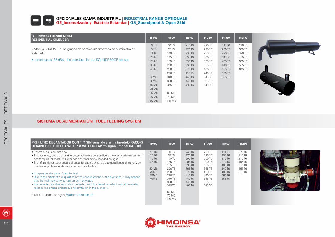
SILENCIOSO RESIDENCIALRESIDENTIAL SILENCER HYW HFW HSW HVW HDW HMW
• Atenúa - 35dBA. En los grupos de versión insonorizada se suministra deestándar.
• It decreases -35 dBA. It is standard for the SOUNDPROOF genset.
6 T69 T614 T620 T625 T635 T645 T6
6 M69 M614 M620 M625 M635 M645 M6
60 T665 T6100 T6125 T6155 T6200 T6250 T6290 T6340 T6350 T6375 T6
60 M670 M6100 M6
245 T6275 T6290 T6305 T6335 T6365 T6370 T6410 T6440 T6445 T6480 T6
220 T6225 T6250 T6300 T6305 T6355 T6400 T6440 T6515 T6555 T6615 T6
110 T6200 T6270 T6310 T6405 T6440 T6485 T6560 T6655 T6
270 T6310 T6370 T6405 T6510 T6555 T6615 T6
OPCIONALES GAMA INDUSTRIAL | INDUSTRIAL RANGE OPTIONALS GE_Insonorizado y Estático Estándar | GS_Soundproof & Open Skid
SISTEMA DE ALIMENTACIÓN_ FUEL FEEDING SYSTEM
PREFILTRO DECANTADOR CON * Y SIN señal de alarma (modelo RACOR)DECANTER PREFILTER WITH * & WITHOUT alarm signal (model RACOR) HYW HFW HSW HVW HDW HMW
• Separa el agua del gasóleo.• En ocasiones, debido a las diferentes calidades del gasóleo o a condensaciones en gran-
des tanques, el combustible puede contener cierta cantidad de agua.• El prefiltro decantador separa el agua del gasoil, evitando que esta llegue al motor y se
produzcan problemas de cavitación en los cilindros.
• It separates the water from the fuel.• Due to the different fuel qualities or the condensations of the big tanks, it may happen
that the fuel may carry certain amount of water.• The decanter prefilter separates the water from the diesel in order to avoid the water
reaches the engine and producing cavitation in the cylinders.
* Kit detección de agua_Water detection kit
20 T625 T635 T645 T6
20 M625M635M645M6
60 T665 T6100 T6125 T6155 T6200 T6250 T6290 T6340 T6350 T6375 T6
60 M670 M6100 M6
245 T6275 T6290 T6305 T6335 T6365 T6370 T6410 T6440 T6445 T6480 T6
220 T6225 T6250 T6300 T6305 T6355 T6400 T6440 T6515 T6555 T6615 T6
110 T6200 T6270 T6310 T6405 T6440 T6485 T6560 T6655 T6
270 T6310 T6370 T6405 T6510 T6555 T6615 T6
OP
CIO
NA
LES
| O
PTI
ON
ALS
110

OP
CIO
NA
LES
| O
PTI
ON
ALS
VÁLVULA 3 VÍAS LLENADO DE COMBUSTIBLE3 WAY VALVE FUEL FILLING
MODELOSMODELS
• Sistema de válvulas preparadas para permitir la toma de combustible, ya sea desde el propio tanque del grupo electrogeno o bien desde un tanque externo. Disponible en conexiones de 1/2” y de 3/8”_ Valves system pre-pared to allow the fuel intake, either from the genset’s own tank or from an external tank. Available in 1/2” and 3/8” fittings.
Sistema preparado para la conexión de mangueras de combustible desde un tanque externo, para permitir tomar el combustible bien desde el propio tanque del electrogeno, bien desde tanque externo.System prepared for the hose fuel connection from an external tank in order to allow the intake either from the genset´s own tank or from an external tank.
Disponible en grupos insonorizados excepto en serie HZA capotados
Available in Soundproofgensets in canopy except in the product range HZA Silent Pack.
BOMBA DE TRASIEGO MANUALMANUAL FUEL TRANSFER PUMP
MODELOSMODELS
• Permite el traspaso manual de combustible desde un tanque externo al tanque del grupo electrógeno_ It allows the transfer of fuel from an external tank to the genset´s tank.
NO disponble en grupos de versión insonorizada con carrocerías tipo A10, B10, C10, D10, E10. y depósito de plástico Nota: se suminis-trará suelta, sólo se entregará montada en chasis con depósitos metálicos. Tampoco disponible en la serie HZA CapotadosNOT available in Soundproof genset in canopy type:A10, B10, C10, D10, E10 and plastic fuel tank. Note: It will supplied loose. Only it will delivered mounted in chassis with metallic fuel tanks. Not availa-ble in the product range HZA Silent Pack.
BOMBA DE TRASIEGO ELÉCTRICAAUTOMATIC FUEL TRANSFER PUMP
MODELOSMODELS
• Bomba eléctrica de trasiego montada en chasis, sistema de nivel de carga_Electric pump mounted in chassis, fuel level system.
Permite el traspaso automático de combustible desde un tanque externo al tanque del grupo electrógeno. El sistema de nivel, detectará cuando el ni-vel del tanque de combustible es bajo para arrancar la bomba y cuando es optimo para pararla_ Allows the automatic transfer of fuel from an external tank to the genset’s tank. The level system, will detect when the level of fuel from the tank is low to start the pump and when it is good to stop it.
Disponible en grupos electrógenos de la gama industrialdiesel agua.
Available for all the industrial diesel water cooled range.
111
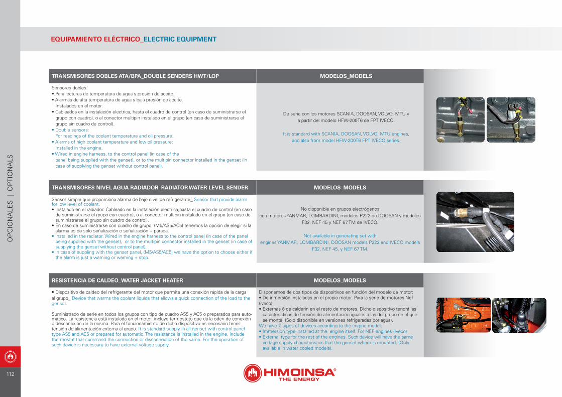
TRANSMISORES DOBLES ATA/BPA_DOUBLE SENDERS HWT/LOP MODELOS_MODELS
Sensores dobles:• Para lecturas de temperatura de agua y presión de aceite.• Alarmas de alta temperatura de agua y baja presión de aceite.
Instalados en el motor.• Cableados en la instalación electrica, hasta el cuadro de control (en caso de suministrarse el
grupo con cuadro), o al conector multipin instalado en el grupo (en caso de suministrarse el grupo sin cuadro de control).
• Double sensors:For readings of the coolant temperature and oil pressure.
• Alarms of high coolant temperature and low oil pressure:Installed in the engine.
• Wired in engine harness, to the control panel (in case of thepanel being supplied with the genset), or to the multipin connector installed in the genset (in case of supplying the genset without control panel).
De serie con los motores SCANIA, DOOSAN, VOLVO, MTU ya partir del modelo HFW-200T6 de FPT IVECO.
It is standard with SCANIA, DOOSAN, VOLVO, MTU engines,and also from model HFW-200T6 FPT IVECO series.
TRANSMISORES NIVEL AGUA RADIADOR_RADIATOR WATER LEVEL SENDER MODELOS_MODELS
Sensor simple que proporciona alarma de bajo nivel de refrigerante_ Sensor that provide alarm for low level of coolant.• Instalado en el radiador. Cableado en la instalación electrica,hasta el cuadro de control (en caso
de suministrarse el grupo con cuadro), o al conector multipin instalado en el grupo (en caso de suministrarse el grupo sin cuadro de control).
• En caso de suministrarse con cuadro de grupo, (M5/AS5/AC5) tenemos la opción de elegir si la alarma es de solo señalización o señalización + parada.
• Installed in the radiator. Wired in the engine harness to the control panel (in case of the panel being supplied with the genset), or to the multipin connector installed in the genset (in case of supplying the genset without control panel).
• In case of suppling with the genset panel, (M5/AS5/AC5) we have the option to choose either if the alarm is just a warning or warning + stop.
No disponible en grupos electrógenoscon motores YANMAR, LOMBARDINI, modelos P222 de DOOSAN y modelos
F32, NEF 45 y NEF 67 TM de IVECO.
Not available in generating set withengines YANMAR, LOMBARDINI, DOOSAN models P222 and IVECO models
F32, NEF 45, y NEF 67 TM.
RESISTENCIA DE CALDEO_WATER JACKET HEATER MODELOS_MODELS
• Dispositivo de caldeo del refrigerante del motor que permite una conexión rápida de la carga al grupo_ Device that warms the coolant liquids that allows a quick connection of the load to the genset.
Suministrado de serie en todos los grupos con tipo de cuadro AS5 y AC5 o preparados para auto-mático. La resistencia está instalada en el motor, incluye termostato que da la oden de conexión o desconexión de la misma. Para el funcionamiento de dicho dispositivo es necesario tener tensión de alimentación externa al grupo. It is standard supply in all genset with control panel type AS5 and AC5 or prepared for automatic. The resistance is installed in the engine, include thermostat that command the connection or disconnection of the same. For the operation of such device is necessary to have external voltage supply.
Disponemos de dos tipos de dispositivos en función del modelo de motor:• De inmersión instaladas en el propio motor. Para la serie de motores Nef (iveco)• Externas ó de calderin en el resto de motores. Dicho dispositivo tendrá las
características de tensión de alimentación iguales a las del grupo en el que se monta. (Solo disponible en versiones refrigeradas por agua).
We have 2 types of devices according to the engine model:• Immersion type installed at the engine itself. For NEF engines (Iveco)• External type for the rest of the engines. Such device will have the same
voltage supply characteristics that the genset where is mounted. (Only available in water cooled models).
EQUIPAMIENTO ELÉCTRICO_ELECTRIC EQUIPMENT
OP
CIO
NA
LES
| O
PTI
ON
ALS
112
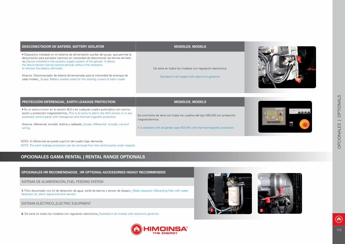
DESCONECTADOR DE BATERÍA_BATTERY ISOLATOR MODELOS_MODELS
• Dispositivo instalado en el sistema de alimentación auxiliar del grupo, que permite la desconexión para periodos inactivos sin necesidad de desconectar las bornas de bate-ría_Device installed in the auxiliary supply system of the genset. It allowsthe disconnection during inactive periods without the necessityto remove the battery terminals.
Alcance: Desconectador de batería dimensionado para la intensidad de arranque de cada modelo_ Scope: Battery isolator sized for the starting current of each model.
De serie en todos los modelos con regulación electrónica.
Standard in all models with electronic governor.
PROTECCIÓN DIFERENCIAL_EARTH LEAKAGE PROTECTION MODELOS_MODELS
• Es un extra a incluir en la versión AC5 o en cualquier cuadro automático con conmu-tación y protección magnetotémica_ This is an extra to add in the AC5 version or in any automatic control panel with changeover and thermal-magnetic protection.
Alcance: diferencial, toroidal, bobina y cableado_Scope: differential, toroidal, coil and wiring.
Se suministra de serie con todos los cuadros del tipo AS5,M5 con protección magnetotérmica.
It is standard with all panels type AS5,M5 with thermal-magnetic protection.
OPCIONALES GAMA RENTAL | RENTAL RANGE OPTIONALS
OPCIONALES HR RECOMENDADOS_ HR OPTIONAL ACCESSORIES HIGHLY RECOMMENDED
SISTEMA DE ALIMENTACIÓN_FUEL FEEDING SYSTEM
1. Filtro decantador con kit de detección de agua, señal de alarma y sensor de disparo_ Water separator (Decanting filter with water detection kit, alarm signal and shot sensor)
SISTEMA ELÉCTRICO_ELECTRIC EQUIPMENT
2. De serie en todos los modelos con regulación electrónica_Standard in all models with electronic governor.1 2
OP
CIO
NA
LES
| O
PTI
ON
ALS
NOTA: El diferencial se puede suprimir del cuadro bajo demanda.NOTE: The earth leakage protection can be removed from the control panel under request.
113
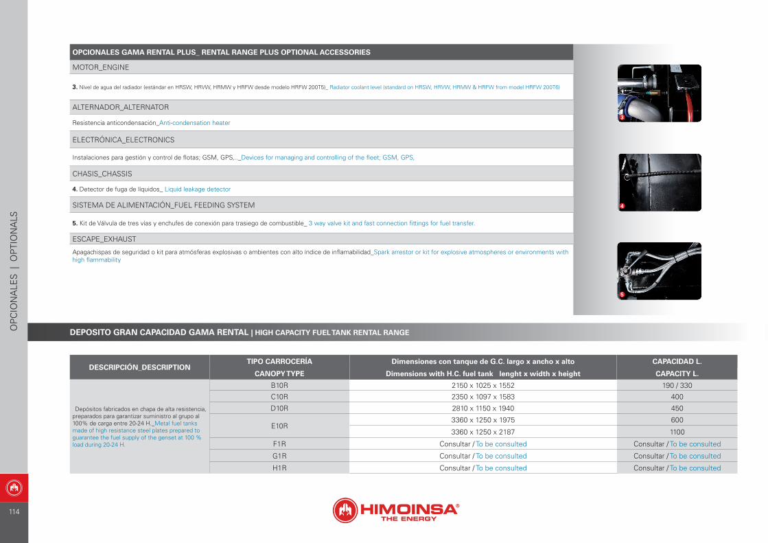
DESCRIPCIÓN_DESCRIPTIONTIPO CARROCERÍA Dimensiones con tanque de G.C. largo x ancho x alto CAPACIDAD L.
CANOPY TYPE Dimensions with H.C. fuel tank lenght x width x height CAPACITY L.
Depósitos fabricados en chapa de alta resistencia, preparados para garantizar suministro al grupo al 100% de carga entre 20-24 H._Metal fuel tanks made of high resistance steel plates prepared to guarantee the fuel supply of the genset at 100 % load during 20-24 H.
B10R 2150 x 1025 x 1552 190 / 330
C10R 2350 x 1097 x 1583 400
D10R 2810 x 1150 x 1940 450
E10R3360 x 1250 x 1975 600
3360 x 1250 x 2187 1100
F1R Consultar / To be consulted Consultar / To be consulted
G1R Consultar / To be consulted Consultar / To be consulted
H1R Consultar / To be consulted Consultar / To be consulted
OPCIONALES GAMA RENTAL PLUS_ RENTAL RANGE PLUS OPTIONAL ACCESSORIES
MOTOR_ENGINE
3. Nivel de agua del radiador (estándar en HRSW, HRVW, HRMW y HRFW desde modelo HRFW 200T5)_ Radiator coolant level (standard on HRSW, HRVW, HRMW & HRFW from model HRFW 200T6)
ALTERNADOR_ALTERNATOR
Resistencia anticondensación_Anti-condensation heater
ELECTRÓNICA_ELECTRONICS
Instalaciones para gestión y control de flotas; GSM, GPS,.._Devices for managing and controlling of the fleet; GSM, GPS,
CHASIS_CHASSIS
4. Detector de fuga de líquidos_ Liquid leakage detector
SISTEMA DE ALIMENTACIÓN_FUEL FEEDING SYSTEM
5. Kit de Válvula de tres vías y enchufes de conexión para trasiego de combustible_ 3 way valve kit and fast connection fittings for fuel transfer.
ESCAPE_EXHAUST
Apagachispas de seguridad o kit para atmósferas explosivas o ambientes con alto índice de inflamabilidad_Spark arrestor or kit for explosive atmospheres or environments with high flammability
3
4
5
DEPOSITO GRAN CAPACIDAD GAMA RENTAL | HIGH CAPACITY FUEL TANK RENTAL RANGEOP
CIO
NA
LES
| O
PTI
ON
ALS
114
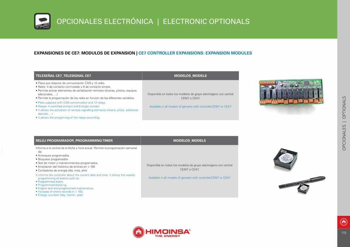
TELESEÑAL CE7_TELESIGNAL CE7 MODELOS_MODELS
• Placa que dispone de comunicación CAN y 12 relés.• Relés: 4 de contacto conmutado y 8 de contacto simple.• Permite activar elementos de señalización remotos (sirenas, pilotos, equipos
adicionales, …)• Permite la programación de los relés en función de las diferentes variables.
• Plate supplied with CAN comunication and 12 relays.• Relays: 4 switched contact and 8 single contact.• It allows the activation of remote signalling elements (sirens, pilots, additional
devices, ...)• It allows the programing of the relays according
Disponible en todos los modelos de grupo electrógeno con centralCEM7 o CEA7.
Available in all models of gensets with controllerCEM7 or CEA7
RELOJ PROGRAMADOR_PROGRAMMING TIMER MODELOS_MODELS
Informa a la central de la fecha y hora actual. Permite la programación semanal de:
• Arranques programados• Bloqueos programados• Test de motor y mantenimientos programados.• Ampliación del histórico de errores en + 100• Contadores de energía (día, mes, año)
It informs the controller about the current date and time. It allows the weekly programming of events such as:
• Programmed starts.• Programmed blocking.• Engine test and programmed maintenance.• Increase of errors records in + 100.• Energy counters (day, month, year)
Disponible en todos los modelos de grupo electrógeno con centralCEM7 o CEA7.
Available in all models of gensets with controllerCEM7 or CEA7
EXPANSIONES DE CE7: MODULOS DE EXPANSION | CE7 CONTROLLER EXPANSIONS: EXPANSION MODULES
OPCIONALES ELECTRÓNICA | ELECTRONIC OPTIONALS
OP
CIO
NA
LES
| O
PTI
ON
ALS
115
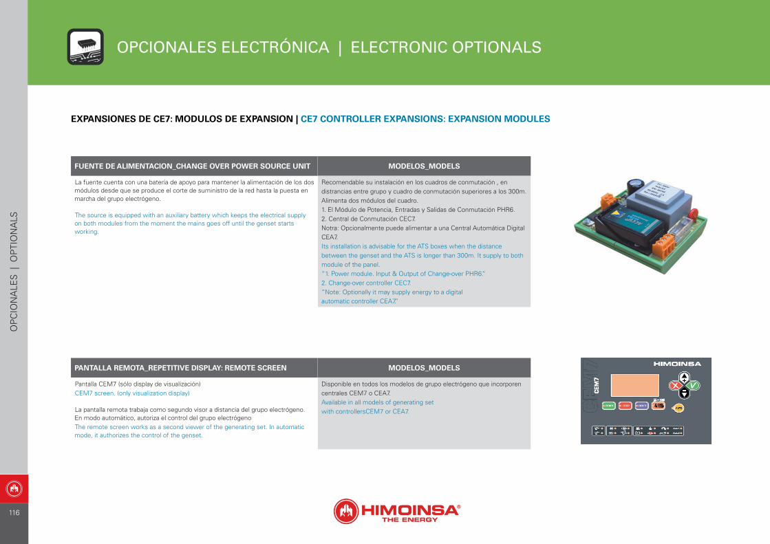
OPCIONALES ELECTRÓNICA | ELECTRONIC OPTIONALS
FUENTE DE ALIMENTACION_CHANGE OVER POWER SOURCE UNIT MODELOS_MODELS
La fuente cuenta con una batería de apoyo para mantener la alimentación de los dos módulos desde que se produce el corte de suministro de la red hasta la puesta en marcha del grupo electrógeno.
The source is equipped with an auxiliary battery which keeps the electrical supply on both modules from the moment the mains goes off until the genset starts working.
Recomendable su instalación en los cuadros de conmutación , en distrancias entre grupo y cuadro de conmutación superiores a los 300m.Alimenta dos módulos del cuadro. 1. El Módulo de Potencia, Entradas y Salidas de Conmutación PHR6. 2. Central de Conmutación CEC7. Notra: Opcionalmente puede alimentar a una Central Automática Digital CEA7.Its installation is advisable for the ATS boxes when the distance between the genset and the ATS is longer than 300m. It supply to both module of the panel. “1. Power module. Input & Output of Change-over PHR6.” 2. Change-over controller CEC7. “Note: Optionally it may supply energy to a digitalautomatic controller CEA7.”
PANTALLA REMOTA_REPETITIVE DISPLAY: REMOTE SCREEN MODELOS_MODELS
Pantalla CEM7 (sólo display de visualización)CEM7 screen. (only visualization display)
La pantalla remota trabaja como segundo visor a distancia del grupo electrógeno. En modo automático, autoriza el control del grupo electrógenoThe remote screen works as a second viewer of the generating set. In automatic mode, it authorizes the control of the genset.
Disponible en todos los modelos de grupo electrógeno que incorporen centrales CEM7 o CEA7.Available in all models of generating setwith controllersCEM7 or CEA7.
EXPANSIONES DE CE7: MODULOS DE EXPANSION | CE7 CONTROLLER EXPANSIONS: EXPANSION MODULES
OP
CIO
NA
LES
| O
PTI
ON
ALS
116
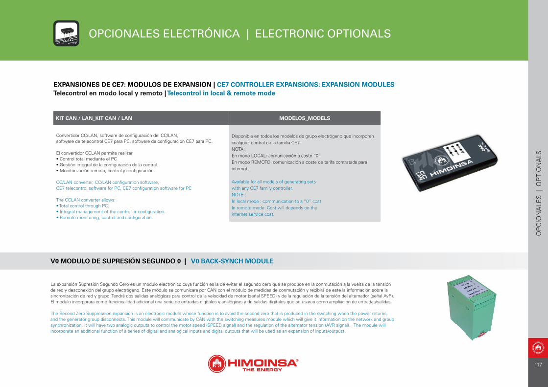
OPCIONALES ELECTRÓNICA | ELECTRONIC OPTIONALS
KIT CAN / LAN_KIT CAN / LAN MODELOS_MODELS
Convertidor CC/LAN, software de configuración del CC/LAN,software de telecontrol CE7 para PC, software de configuración CE7 para PC.
El convertidor CCLAN permite realizar• Control total mediante el PC• Gestión integral de la configuración de la central.• Monitorización remota, control y configuración.
CC/LAN converter, CC/LAN configuration software,CE7 telecontrol software for PC, CE7 configuration software for PC
The CCLAN converter allows:• Total control through PC.• Integral management of the controller configuration.• Remote monitoring, control and configuration.
Disponible en todos los modelos de grupo electrógeno que incorporen cualquier central de la familia CE7.NOTA: En modo LOCAL: comunicación a coste “0”En modo REMOTO: comunicación a coste de tarifa contratada para internet.
Available for all models of generating setswith any CE7 family controller.NOTE :In local mode : communication to a “0” costIn remote mode: Cost will depends on theinternet service cost.
EXPANSIONES DE CE7: MODULOS DE EXPANSION | CE7 CONTROLLER EXPANSIONS: EXPANSION MODULESTelecontrol en modo local y remoto | Telecontrol in local & remote mode
V0 MODULO DE SUPRESIÓN SEGUNDO 0 | V0 BACK-SYNCH MODULE
La expansión Supresión Segundo Cero es un módulo electrónico cuya función es la de evitar el segundo cero que se produce en la conmutación a la vuelta de la tensión de red y desconexión del grupo electrógeno. Este módulo se comunicara por CAN con el módulo de medidas de conmutación y recibirá de este la información sobre la sincronización de red y grupo. Tendrá dos salidas analógicas para control de la velocidad de motor (señal SPEED) y de la regulación de la tensión del alternador (señal AvR). El modulo incorporara como funcionalidad adicional una serie de entradas digitales y analógicas y de salidas digitales que se usaran como ampliación de entradas/salidas.
The Second Zero Suppression expansion is an electronic module whose function is to avoid the second zero that is produced in the switching when the power returns and the generator group disconnects. This module will communicate by CAN with the switching measures module which will give it information on the network and group synchronization. It will have two analogic outputs to control the motor speed (SPEED signal) and the regulation of the alternator tension (AVR signal). The module will incorporate an additional function of a series of digital and analogical inputs and digital outputs that will be used as an expansion of inputs/outputs.
OP
CIO
NA
LES
| O
PTI
ON
ALS
117
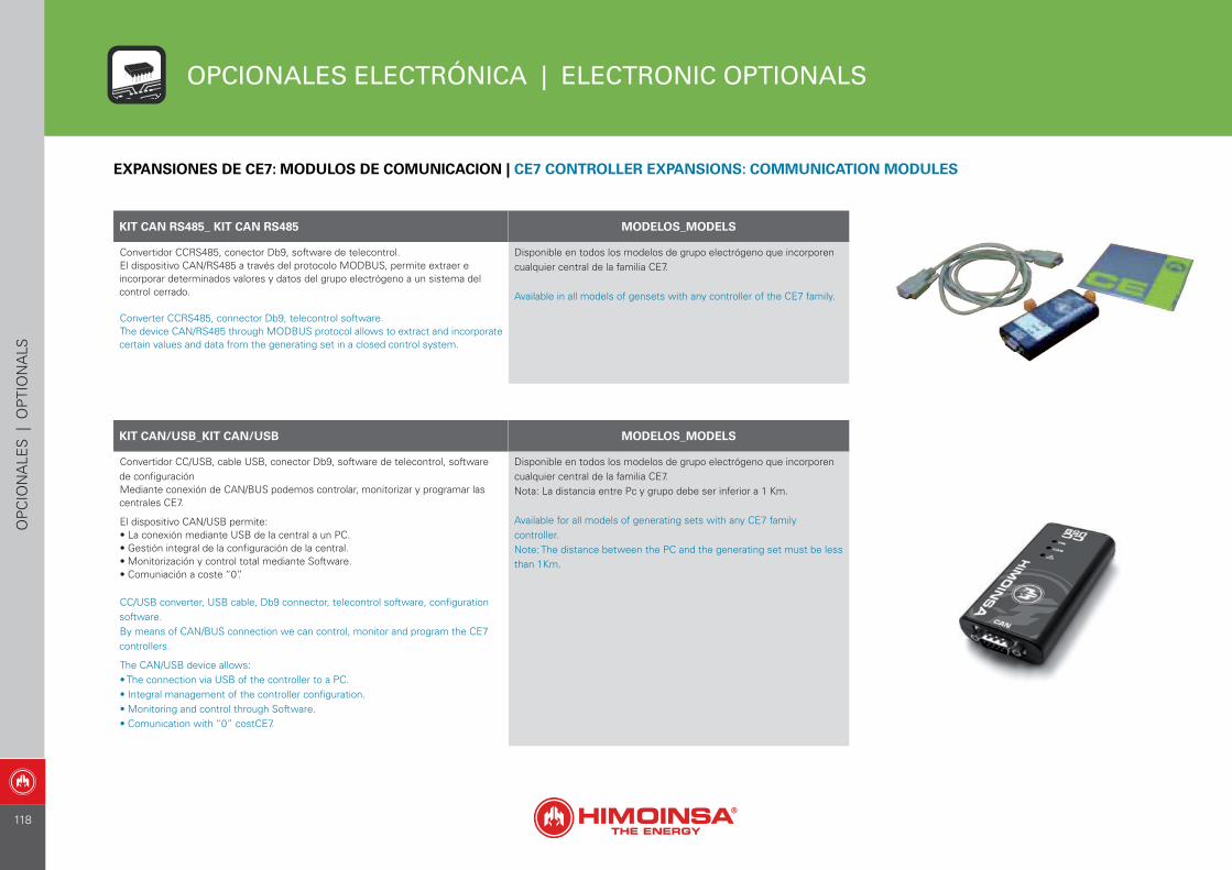
OPCIONALES ELECTRÓNICA | ELECTRONIC OPTIONALS
KIT CAN RS485_ KIT CAN RS485 MODELOS_MODELS
Convertidor CCRS485, conector Db9, software de telecontrol. El dispositivo CAN/RS485 a través del protocolo MODBUS, permite extraer e incorporar determinados valores y datos del grupo electrógeno a un sistema del control cerrado.
Converter CCRS485, connector Db9, telecontrol software.The device CAN/RS485 through MODBUS protocol allows to extract and incorporate certain values and data from the generating set in a closed control system.
Disponible en todos los modelos de grupo electrógeno que incorporen cualquier central de la familia CE7.
Available in all models of gensets with any controller of the CE7 family.
KIT CAN/USB_KIT CAN/USB MODELOS_MODELS
Convertidor CC/USB, cable USB, conector Db9, software de telecontrol, software de configuraciónMediante conexión de CAN/BUS podemos controlar, monitorizar y programar las centrales CE7.
El dispositivo CAN/USB permite:• La conexión mediante USB de la central a un PC.• Gestión integral de la configuración de la central.• Monitorización y control total mediante Software.• Comuniación a coste “0”.
CC/USB converter, USB cable, Db9 connector, telecontrol software, configuration software.By means of CAN/BUS connection we can control, monitor and program the CE7 controllers.
The CAN/USB device allows:• The connection via USB of the controller to a PC.• Integral management of the controller configuration.• Monitoring and control through Software.• Comunication with “0” costCE7.
Disponible en todos los modelos de grupo electrógeno que incorporen cualquier central de la familia CE7.Nota: La distancia entre Pc y grupo debe ser inferior a 1 Km.
Available for all models of generating sets with any CE7 family controller.Note: The distance between the PC and the generating set must be less than 1Km.
EXPANSIONES DE CE7: MODULOS DE COMUNICACION | CE7 CONTROLLER EXPANSIONS: COMMUNICATION MODULES
OP
CIO
NA
LES
| O
PTI
ON
ALS
118
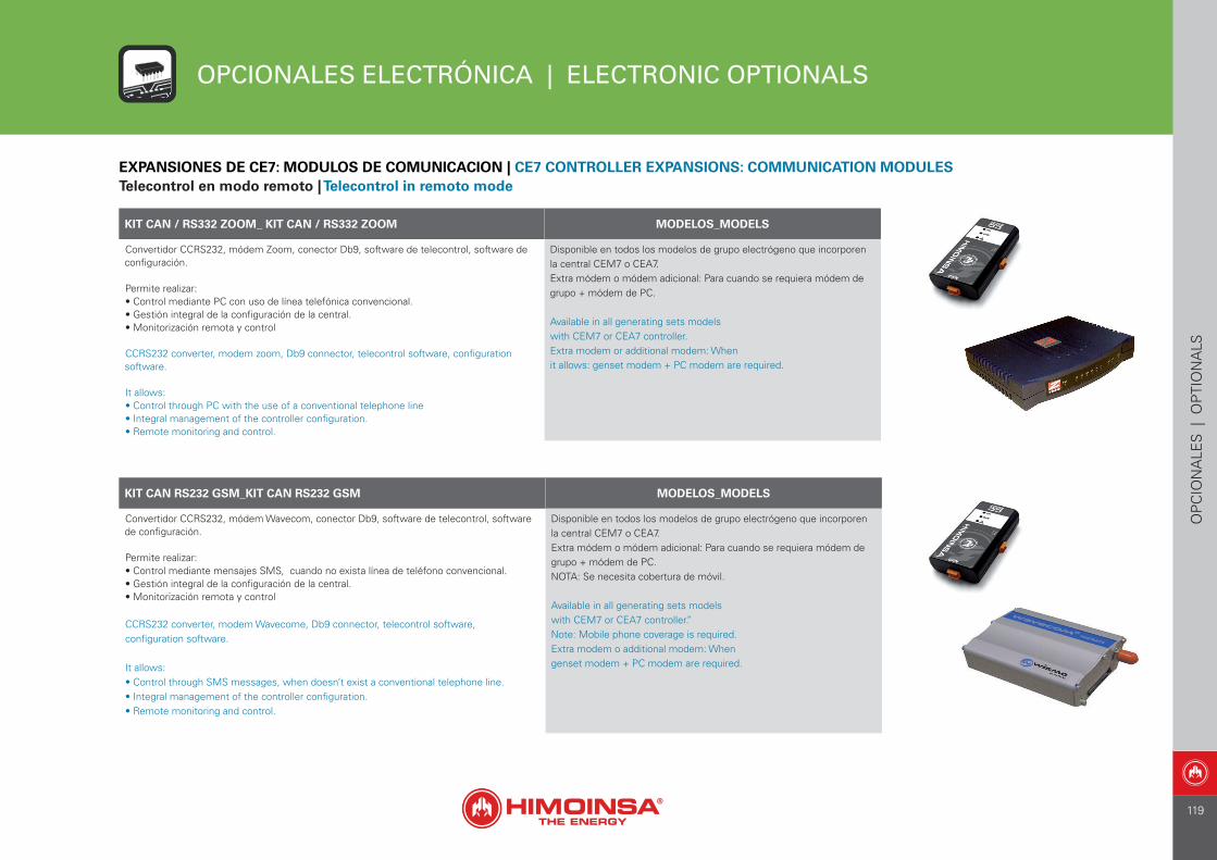
OPCIONALES ELECTRÓNICA | ELECTRONIC OPTIONALS
KIT CAN / RS332 ZOOM_ KIT CAN / RS332 ZOOM MODELOS_MODELS
Convertidor CCRS232, módem Zoom, conector Db9, software de telecontrol, software de configuración.
Permite realizar:• Control mediante PC con uso de línea telefónica convencional.• Gestión integral de la configuración de la central.• Monitorización remota y control
CCRS232 converter, modem zoom, Db9 connector, telecontrol software, configuration software.
It allows:• Control through PC with the use of a conventional telephone line• Integral management of the controller configuration.• Remote monitoring and control.
Disponible en todos los modelos de grupo electrógeno que incorporen la central CEM7 o CEA7.Extra módem o módem adicional: Para cuando se requiera módem de grupo + módem de PC.
Available in all generating sets modelswith CEM7 or CEA7 controller.Extra modem or additional modem: Whenit allows: genset modem + PC modem are required.
KIT CAN RS232 GSM_KIT CAN RS232 GSM MODELOS_MODELS
Convertidor CCRS232, módem Wavecom, conector Db9, software de telecontrol, software de configuración.
Permite realizar:• Control mediante mensajes SMS, cuando no exista línea de teléfono convencional.• Gestión integral de la configuración de la central.• Monitorización remota y control
CCRS232 converter, modem Wavecome, Db9 connector, telecontrol software,configuration software.
It allows:• Control through SMS messages, when doesn’t exist a conventional telephone line.• Integral management of the controller configuration.• Remote monitoring and control.
Disponible en todos los modelos de grupo electrógeno que incorporen la central CEM7 o CEA7.Extra módem o módem adicional: Para cuando se requiera módem de grupo + módem de PC.NOTA: Se necesita cobertura de móvil.
Available in all generating sets modelswith CEM7 or CEA7 controller.”Note: Mobile phone coverage is required.Extra modem o additional modem: Whengenset modem + PC modem are required.
EXPANSIONES DE CE7: MODULOS DE COMUNICACION | CE7 CONTROLLER EXPANSIONS: COMMUNICATION MODULESTelecontrol en modo remoto | Telecontrol in remoto mode
OP
CIO
NA
LES
| O
PTI
ON
ALS
119

OPCIONALES ELECTRÓNICA | ELECTRONIC OPTIONALS
KIT CAN / RS32 GPRS/GPS MODELOS_MODELS
Convertidor CCRS232, antena GSM y GPS, conectores, software de telecontrol,software de configuración.
Permite realizar:• Control mediante mensajes SMS, cuando no exista línea de teléfono convencional. Envia SMS con las coordinadas GPS de la posición del grupo electrógeno.• Gestión integral de la configuración de la central.• Monitorización remota y control
CCRS232 converter, GSM and GPS antennas,connectors, telecontrol software, configuration software.
It allows:• Control through SMS messages, when doesn’t exist a conventional telephone line.• Integral management of the controller configuration.• Remote monitoring and control.• Genset positioning through GPS and alarms when it leave a preset perimeter, etc.
Disponible en todos los modelos de grupo electrógeno que incorporen cualquier central de la familia CE7.Extra módem o módem adicional: Para cuando se requiera módem de grupo + módem de PC.NOTA: Se necesita cobertura de móvil.
Available in all generating sets models with CE7 family controller.Note: Mobile phone coverage is required.Extra modem o additional modem: When genset modem + PC modem are required.”
EXPANSIONES DE CE7: MODULOS DE COMUNICACION | CE7 CONTROLLER EXPANSIONS: COMMUNICATION MODULESTelecontrol en modo remoto | Telecontrol in remoto mode
OP
CIO
NA
LES
| O
PTI
ON
ALS
120
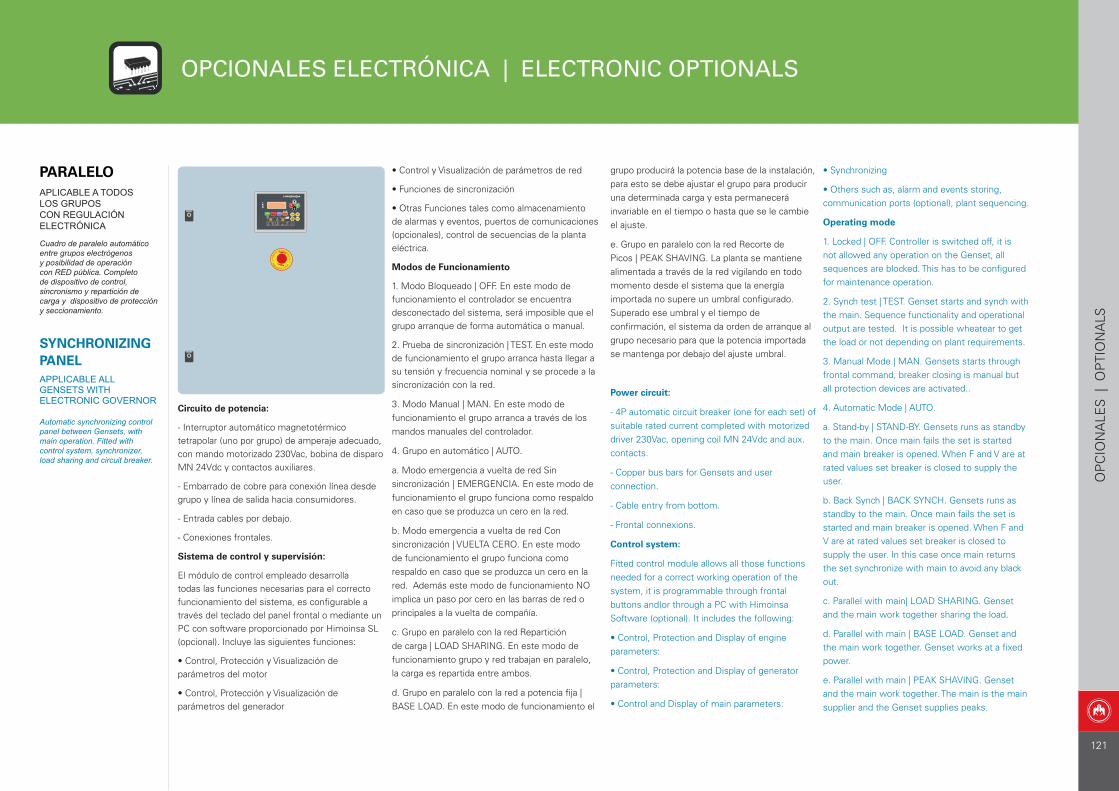
OPCIONALES ELECTRÓNICA | ELECTRONIC OPTIONALS
OP
CIO
NA
LES
| O
PTI
ON
ALS
Circuito de potencia:
- Interruptor automático magnetotérmico tetrapolar (uno por grupo) de amperaje adecuado, con mando motorizado 230Vac, bobina de disparo MN 24Vdc y contactos auxiliares.
- Embarrado de cobre para conexión línea desde grupo y línea de salida hacia consumidores.
- Entrada cables por debajo.
- Conexiones frontales.
Sistema de control y supervisión:
El módulo de control empleado desarrolla todas las funciones necesarias para el correcto funcionamiento del sistema, es configurable a través del teclado del panel frontal o mediante un PC con software proporcionado por Himoinsa SL (opcional). Incluye las siguientes funciones:
• Control, Protección y Visualización de parámetros del motor
• Control, Protección y Visualización de parámetros del generador
• Synchronizing
• Others such as, alarm and events storing, communication ports (optional), plant sequencing.
Operating mode
1. Locked | OFF. Controller is switched off, it is not allowed any operation on the Genset, all sequences are blocked. This has to be configured for maintenance operation.
2. Synch test | TEST. Genset starts and synch with the main. Sequence functionality and operational output are tested. It is possible wheatear to get the load or not depending on plant requirements.
3. Manual Mode | MAN. Gensets starts through frontal command, breaker closing is manual but all protection devices are activated..
4. Automatic Mode | AUTO.
a. Stand-by | STAND-BY. Gensets runs as standby to the main. Once main fails the set is started and main breaker is opened. When F and V are at rated values set breaker is closed to supply the user.
b. Back Synch | BACK SYNCH. Gensets runs as standby to the main. Once main fails the set is started and main breaker is opened. When F and V are at rated values set breaker is closed to supply the user. In this case once main returns the set synchronize with main to avoid any black out.
c. Parallel with main| LOAD SHARING. Genset and the main work together sharing the load.
d. Parallel with main | BASE LOAD. Genset and the main work together. Genset works at a fixed power.
e. Parallel with main | PEAK SHAVING. Genset and the main work together. The main is the main supplier and the Genset supplies peaks.
• Control y Visualización de parámetros de red
• Funciones de sincronización
• Otras Funciones tales como almacenamiento de alarmas y eventos, puertos de comunicaciones (opcionales), control de secuencias de la planta eléctrica.
Modos de Funcionamiento
1. Modo Bloqueado | OFF. En este modo de funcionamiento el controlador se encuentra desconectado del sistema, será imposible que el grupo arranque de forma automática o manual.
2. Prueba de sincronización | TEST. En este modo de funcionamiento el grupo arranca hasta llegar a su tensión y frecuencia nominal y se procede a la sincronización con la red.
3. Modo Manual | MAN. En este modo de funcionamiento el grupo arranca a través de los mandos manuales del controlador.
4. Grupo en automático | AUTO.
a. Modo emergencia a vuelta de red Sin sincronización | EMERGENCIA. En este modo de funcionamiento el grupo funciona como respaldo en caso que se produzca un cero en la red.
b. Modo emergencia a vuelta de red Con sincronización | VUELTA CERO. En este modo de funcionamiento el grupo funciona como respaldo en caso que se produzca un cero en la red. Además este modo de funcionamiento NO implica un paso por cero en las barras de red o principales a la vuelta de compañía.
c. Grupo en paralelo con la red Repartición de carga | LOAD SHARING. En este modo de funcionamiento grupo y red trabajan en paralelo, la carga es repartida entre ambos.
d. Grupo en paralelo con la red a potencia fija | BASE LOAD. En este modo de funcionamiento el
grupo producirá la potencia base de la instalación, para esto se debe ajustar el grupo para producir una determinada carga y esta permanecerá invariable en el tiempo o hasta que se le cambie el ajuste.
e. Grupo en paralelo con la red Recorte de Picos | PEAK SHAVING. La planta se mantiene alimentada a través de la red vigilando en todo momento desde el sistema que la energía importada no supere un umbral configurado. Superado ese umbral y el tiempo de confirmación, el sistema da orden de arranque al grupo necesario para que la potencia importada se mantenga por debajo del ajuste umbral.
Power circuit:
- 4P automatic circuit breaker (one for each set) of suitable rated current completed with motorized driver 230Vac, opening coil MN 24Vdc and aux. contacts.
- Copper bus bars for Gensets and user connection.
- Cable entry from bottom.
- Frontal connexions.
Control system:
Fitted control module allows all those functions needed for a correct working operation of the system, it is programmable through frontal buttons and(or through a PC with Himoinsa Software (optional). It includes the following:
• Control, Protection and Display of engine parameters:
• Control, Protection and Display of generator parameters:
• Control and Display of main parameters:
PARALELOAPLICABLE A TODOS LOS GRUPOS CON REGULACIÓN ELECTRÓNICA
Cuadro de paralelo automático entre grupos electrógenos y posibilidad de operación con RED pública. Completo de dispositivo de control, sincronismo y repartición de carga y dispositivo de protección y seccionamiento.
SYNCHRONIZING PANELAPPLICABLE ALL GENSETS WITH ELECTRONIC GOVERNOR
Automatic synchronizing control panel between Gensets, with main operation. Fitted with control system, synchronizer, load sharing and circuit breaker.
121