A300B2 ATA 79
128
G E CF6 - 50 HIGHLIGHTS __________ REVISION NO. 52 Mar 01/07 Pages which have been revised are outlined below, together with the Highlights of the Revision -------------------------------------------------------------------------------------- CH/SE/SU C REASON FOR CHANGE EFFECTIVITY PAGES -------------------------------------------------------------------------------------- CHAPTER 79 __________ L.E.P. 1- 2 Revised to Reflect this revision indicating new,revised, and/or deleted pages 79-HIGHLIGHTS REVISION NO. 52 Page 1 of 1 JAS Mar 01/07
-
Upload
jimbokhepel -
Category
Documents
-
view
235 -
download
3
description
AIRBUS A300B2 aircraft maintenance manual AMMATA CHAPTER
Transcript of A300B2 ATA 79

������������ � G E � � � � CF6 - 50 � ������������ HIGHLIGHTS __________
REVISION NO. 52 Mar 01/07
Pages which have been revised are outlined below, together with the Highlights of theRevision
--------------------------------------------------------------------------------------CH/SE/SU C REASON FOR CHANGE EFFECTIVITY PAGES--------------------------------------------------------------------------------------
CHAPTER 79__________
L.E.P. 1- 2 Revised to Reflect this revision indicating new,revised, and/or deleted pages
79-HIGHLIGHTS REVISION NO. 52 Page 1 of 1 JAS Mar 01/07

������������ � G E � � � � CF6 - 50 � ������������ CHAPTER 79 __________
OIL
LIST OF EFFECTIVE PAGES _______________________ N, R or D indicates pages which are New, Revised or Deleted respectively Remove and insert the affected pages and complete the Record of Revisions and the Record of Temporary Revisions as necessary
CH/SE/SU C PAGE DATE CH/SE/SU C PAGE DATE CH/SE/SU C PAGE DATE
RECORD 79-11-01 201 Oct01/91 79-22-01 401 Apr01/89OF TEMP. 79-11-01 202 Oct30/81 79-22-01 402 Apr01/89REVISION 79-11-01 203 Oct01/91 79-22-01 403 Apr01/89 79-11-01 204 Oct01/91 79-22-02 401 Jan01/88L.E.P. R 1- 2 Mar01/07 79-11-01 205 Oct01/92 79-22-02 402 Jan30/82T. of C. 1 Mar01/00 79-11-01 206 Oct01/92 79-22-02 403 Jan30/82T. of C. 2 Mar01/00 79-22-02 404 Jan30/82T. of C. 3 Mar01/00 79-20-00 1 Jan01/88 79-22-02 405 Jan30/82 79-20-00 2 Oct30/81 79-22-02 406 Oct01/9279-00-00 1 Apr30/82 79-20-00 3 Jul01/85 79-22-03 301 Jul01/8579-00-00 2 Jul01/88 79-20-00 4 Oct30/81 79-22-03 302 Jul01/8579-00-00 3 Jul01/88 79-20-00 5 Jul01/85 79-22-03 303 Oct01/8979-00-00 4 Jul01/88 79-20-00 6 Jul01/85 79-22-03 304 Jul01/8579-00-00 101 Jul30/82 79-20-00 7 Jul01/85 79-22-03 305 Jul01/8579-00-00 201 Apr30/80 79-20-00 8 Jul01/85 79-22-03 306 Oct01/8979-00-00 202 Mar01/99 79-20-00 9 Oct30/81 79-22-03 307 Oct01/8979-00-00 203 Mar01/99 79-20-00 10 Jul01/85 79-22-03 308 Oct01/8979-00-00 204 Mar01/99 79-20-00 11 Jul01/85 79-22-03 309 Oct01/9379-00-00 205 Mar01/9979-00-00 206 Mar01/99 79-21-01 301 Oct01/93 79-30-00 1 Jan01/8879-00-00 207 Mar01/99 79-21-01 302 Oct01/93 79-30-00 2 Oct30/8179-00-00 208 Jul01/88 79-21-01 303 Oct01/93 79-30-00 101 Jan01/8879-00-00 209 Oct01/96 79-21-01 304 Oct01/93 79-30-00 601 Oct30/8179-00-00 210 Mar01/00 79-21-01 305 Oct01/9379-00-00 211 Oct01/96 79-21-01 306 Oct01/93 79-31-00 1 Jan01/8879-00-00 212 Oct01/96 79-21-01 307 Oct01/93 79-31-00 2 Oct30/8179-00-00 213 Oct01/96 79-21-01 308 Oct01/93 79-31-00 3 Oct30/8179-00-00 214 Oct01/96 79-21-01 309 Oct01/93 79-31-11 401 Jan01/8879-00-00 215 Oct01/96 79-21-01 310 Oct01/93 79-31-11 402 Jul30/8079-00-00 216 Oct01/96 79-21-01 311 Oct01/93 79-31-11 403 Jan30/8279-00-00 217 Oct01/96 79-21-01 401 Jan30/8279-00-00 218 Oct01/96 79-21-01 402 Oct30/81 79-32-00 1 Mar01/9979-00-00 401 Jan01/88 79-21-01 403 Oct30/81 79-32-00 2 Mar01/9979-00-00 402 Mar01/00 79-21-01 404 Oct30/81 79-32-00 3 Mar01/9979-00-00 403 Mar01/00 79-21-01 405 Oct01/91 79-32-11 401 Jan30/8279-00-00 404 Mar01/00 79-21-01 406 Oct01/92 79-32-11 402 Jul30/8079-00-00 405 Mar01/00 79-32-11 403 Jan30/82 79-22-01 301 Oct01/9379-10-00 1 Oct30/81 79-22-01 302 Oct01/93 79-33-00 1 Mar01/9979-10-00 2 Oct30/81 79-22-01 303 Oct01/93 79-33-00 2 Mar01/9979-10-00 3 Oct30/81 79-22-01 304 Oct01/93 79-33-00 3 Mar01/99 79-22-01 305 Oct01/93 79-33-11 401 Jan30/82
79-L.E.P. Page 1 JAS Mar 01/07
������������ � G E � � � � CF6 - 50 � ������������CH/SE/SU C PAGE DATE CH/SE/SU C PAGE DATE CH/SE/SU C PAGE DATE
79-33-11 402 Jul30/8079-33-11 403 Jan30/82
79-34-00 1 Jan01/8879-34-00 2 Oct30/8179-34-00 3 Oct30/8179-34-11 401 Jan01/8879-34-11 402 Jan30/8279-34-11 403 Dec30/7979-34-11 404 Jan30/82
79-35-00 1 Jan01/8879-35-00 2 Apr30/8079-35-00 3 Jul30/8179-35-11 401 Jan30/8279-35-11 402 Dec30/7979-35-11 403 Jan30/82
79-L.E.P. Page 2 JAS Mar 01/07

������������ � G E � � � � CF6 - 50 � ������������ CHAPTER 79 __________
OIL
TABLE OF CONTENTS _________________
SUBJECT CH/SE/SU C PAGE EFFECTIVITY _______ ________ _ ____ ________ GENERAL 79-00-00 _______ Description and Operation 1 ALL Fault Isolation Manual 101 ALL Maintenance Practices 201 ALL Procedure 202 ALL Servicing 203 ALL Inspection/Check 206 ALL Cleaning 212 ALL Engine Oil Quantity Check by 401 ALL Dipstick Prior to Each Flight Reference : MMEL Section 1-79, 401 ALL Item 1 Oil Filter Clogging - 402 ALL Daily or Layover Check Reference : MEL Section 1-79, 402 ALL Item 5R Oil Filter Clogging System (FAA 402 ALL Only)R REFERENCE : MMEL 79-30-04 (FAA 402 ALL Only) STORAGE 79-10-00 _______ Description and Operation 1 ALL
OIL TANK ASSY 79-11-01 Maintenance Practices 201 ALL Procedure 201 ALL Removal 201 ALL Installation 203 ALL Test 204 ALL Inspection/Check 205 ALL Approved Repairs 206 ALL DISTRIBUTION 79-20-00 ____________ Description and Operation 1 ALL Component Location 1 ALL Lube and Scavenge Pump 5 ALL Scavenge Oil Filter 5 ALL Fuel Oil Heat Exchanger 7 ALL Lubrication and Pressurization of 7 ALL the Oil Seals Sump Air Pressure Discharge 10 ALL Drainage of the Oil Seals 10 ALL
LUBE AND SCAVENGE PUMP 79-21-01 Servicing 301 ALL Procedure 302 ALL Lube Filter Removal/Installation 302 ALL
79-CONTENTS Page 1 JAS Mar 01/00

������������ � G E � � � � CF6 - 50 � ������������ SUBJECT CH/SE/SU C PAGE EFFECTIVITY _______ ________ _ ____ ________ Inlet Screen Removal/Installation 306 ALL (Configurations 01 and 03) Inlet Screen Removal/Installation 306 ALL (Configuration 02) Plug (Magnetic Fault Isolation 310 ALL Provision) Removal/Installation Close-Up and Test 311 ALL Removal/Installation 401 ALL Procedure 401 ALL Removal 401 ALL Installation 404 ALL Test 405 ALL
SCAVENGE OIL FILTER 79-22-01 Servicing 301 ALL Procedure 302 ALL Filter Element Removal/ 302 ALL Installation Cleaning 302 ALL Installation of Filter Element 304 ALL Close-up and Tests 305 ALL Removal/Installation 401 ALL Procedure 401 ALL Removal 401 ALL Installation 401 ALL FUEL/OIL HEAT EXCHANGER 79-22-02 Removal/Installation 401 ALL Procedure 401 ALL Removal 402 ALL Preparation of Replacement 402 ALL Component Installation 402 ALL Tests and Close-Up 406 ALL MAGNETIC PLUG 79-22-03 Servicing 301 ALL Procedure 301 ALL INDICATING 79-30-00 __________ Description and Operation 1 ALL Fault Isolation Manual 101 ALL Inspection/Check 601 ALL
OIL QUANTITY 79-31-00 Description and Operation 1 ALL Component Location 1 ALL OIL QUANTITY TRANSMITTER 79-31-11 Removal/Installation 401 ALL Procedure 401 ALL Removal 401 ALL Installation 403 ALL Test 403 ALL
79-CONTENTSR Page 2 JAS Mar 01/00

������������ � G E � � � � CF6 - 50 � ������������ SUBJECT CH/SE/SU C PAGE EFFECTIVITY _______ ________ _ ____ ________
OIL TEMPERATURE INDICATING 79-32-00 Description and Operation 1 ALL Component Location 1 ALL OIL TEMPERATURE SENSOR 79-32-11 Removal/Installation 401 ALL Procedure 401 ALL Removal 401 ALL Installation 401 ALL
OIL PRESSURE 79-33-00 Description and Operation 1 ALL Component Location 1 ALL OIL PRESSURE TRANSMITTER 79-33-11 Removal/Installation 401 ALL Procedure 401 ALL Removal 401 ALL Installation 403 ALL Test 403 ALL
LOW OIL PRESSURE WARNING 79-34-00 Description and Operation 1 ALL Component Location 1 ALL LOW OIL PRESSURE SWITCH 79-34-11 Removal/Installation 401 ALL Procedure 402 ALL Removal 402 ALL Installation 402 ALL Tests 402 ALL
SCAVENGE OIL FILTER CLOGGING 79-35-00 INDICATING Description and Operation 1 ALL Component Location 1 ALL OIL FILTER CLOGGING SWITCH 79-35-11 Removal/Installation 401 ALL Procedure 401 ALL Removal 401 ALL Installation 403 ALL Test 403 ALL
79-CONTENTSR Page 3 JAS Mar 01/00

������������ � G E � � � � CF6 - 50 � ������������ GENERAL - DESCRIPTION AND OPERATION ___________________________________
1. General _______ The engine lubricating system is of a self-contained recirculating type. The oil contained in the tank located on the RH side of the engine is sent to the areas to be lubricated by means of the lube pump. The scavenge pumps return oil to the tank through a filter element and a heat-exchanger. Pressure switches located at different points in the lubricating system allow indications to be displayed in the flight compartment.
2. Description and Operation _________________________ The lube and scavenge system is made up of lines located inside and outside the engine. It comprises :
A. Oil Supply The oil supply system provides the oil required for lubrication of the engine bearings, bevel gear and the accessory gearbox radial and horizontal shafts. The oil supply system is made up of : - An oil tank located in the 5 oLclock position on the fan case. - A vane-type lube pump located on the front face of the accessory gearbox. - A filter element in the oil supply pump.
B. Oil Scavenge The oil scavenge system cools, filters and collects the oil used in order to prepare it for recirculation. The oil scavenge system is made up of : - Five vane-type scavenge pumps incorporated in the same housing as the lube pump. - A scavenge oil filter element located behind the accessory gearbox approximately in the 8 oLclock position. - An oil/fuel heat-exchanger attached on the fuel pump support bracket. - A master chip detector plug located on the return line between the oil pump and the scavenge oil filter element.
C. Oil Seal PressurizationR LP compressor discharge provides the housing oil seals with pressureR sealing.
D. Housing Air Venting This system vents air which enters the housing through the oil seals in order to maintain a differential pressure across the oil seals.
E. Oil Seal Drainage This drainage system drains oil leakage from the oil seals to the atmosphere. F. Indicating The indicating system allows the following functions to be monitored from the flight compartment :
�������������������������������������������������������������� �EFFECTIVITY: ALL ������������������������������������������������������������������� 79-00-00 � � � � Page 1 � � JAS Apr 30/82

������������ � G E � � � � CF6 - 50 � ������������ - Oil quantity in the tank is sensed by a sensor in oil tank and indicated within ± 1 quart (0.946 liters) accuracy by an oil quantity gage in the cockpit. - Supply oil pressure. Oil pressure, displayed on the cockpit indicator, is the pressure differential between the lube supply pressure measured downstream of the lube pump and sump vent system pressure as measured at the accessory gearbox. - Oil temperature in the return line. Oil temperature, indicated on the cockpit oil temperature indicator, is scavenge oil temperature. The sensor is inserted into the oil stream just before the scavenge oil filter. - Scavenge oil filter clogging. A differential pressure switch located on the scavenge oil filter closes if the pressure is above 30 psi and acti- vates corresponding warning. - Oil pressure drop. A warning light comes on while the corresponding aural warning sounds when oil pressure drops below 11 psi (0.77 bar).
R **ON A/C 001-101, 103-999,
(Ref. Fig. 001 )
�������������������������������������������������������������� �EFFECTIVITY: ALL ������������������������������������������������������������������� 79-00-00 � � � �R Page 2 � � JAS Jul 01/88

������������ � G E � � � � CF6 - 50 � ������������
Lubricating System - Schematic Figure 001
��������������������������������������������������������������R �EFFECTIVITY: 001-101, 103-999, ������������������������������������������������������������������� 79-00-00 � � � � Page 3- 4 � � JAS Jul 01/88

������������ � G E � � � � CF6 - 50 � ������������ GENERAL - FAULT ISOLATION _________________________
Refer to FI/MM 79-00-00, P. Block 101.
�������������������������������������������������������������� �EFFECTIVITY: ALL ������������������������������������������������������������������� 79-00-00 � � � �R Page 101 � � JAS Jul 30/82

������������ � G E � � � � CF6 - 50 � ������������ GENERAL - MAINTENANCE PRACTICES _______________________________
General (Ref. Fig. 201 ) _______
Checking Oil Level Figure 201
The information presented for system maintenance applies to the entire system. Maintenance information which applies to an individual component is presented as part of the maintenance information for the specific component. WARNING : SYNTHETIC LUBRICANTS USED IN AIRCRAFT TURBINE ENGINES, CONTAIN ADDITI- _______ VES WHICH ARE READILY ABSORBED THROUGH THE SKIN AND ARE HIGHLY TOXIC. EXCESSIVE AND/OR PROLONGED EXPOSURE OF THESE LUBRICANTS TO THE SKIN SHOULD BE AVOIDED
1. Equipment and Materials _______________________ NOTE : Equivalent substitutes may be used instead of the following items. ____ ------------------------------------------------------------------------------- ITEM DESIGNATION -------------------------------------------------------------------------------R A. Material C02-019 Oil Engine (Ref. 20-32-00)R B. Material C02-033 Petrolatum (Ref. 20-32-00)R C. Material C04-001 Methyl-Ethyl-Ketone (Ref. 20-32-00)
�������������������������������������������������������������� �EFFECTIVITY: ALL ������������������������������������������������������������������� 79-00-00 � � � � Page 201 � � JAS Apr 30/80
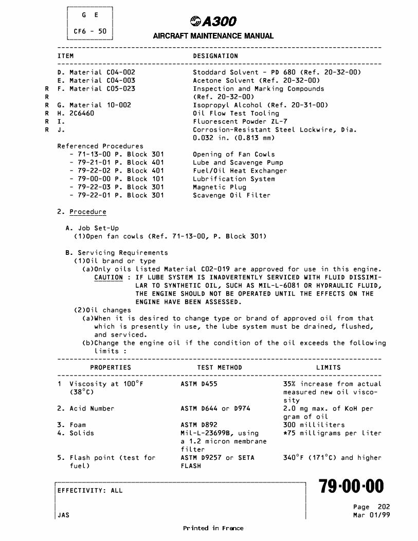
������������ � G E � � � � CF6 - 50 � ������������ ------------------------------------------------------------------------------- ITEM DESIGNATION ------------------------------------------------------------------------------- D. Material C04-002 Stoddard Solvent - PD 680 (Ref. 20-32-00) E. Material C04-003 Acetone Solvent (Ref. 20-32-00)R F. Material C05-023 Inspection and Marking CompoundsR (Ref. 20-32-00)R G. Material 10-002 Isopropyl Alcohol (Ref. 20-31-00)R H. 2C6460 Oil Flow Test ToolingR I. Fluorescent Powder ZL-7R J. Corrosion-Resistant Steel Lockwire, Dia. 0.032 in. (0.813 mm) Referenced Procedures - 71-13-00 P. Block 301 Opening of Fan Cowls - 79-21-01 P. Block 401 Lube and Scavenge Pump - 79-22-02 P. Block 401 Fuel/Oil Heat Exchanger - 79-00-00 P. Block 101 Lubrification System - 79-22-03 P. Block 301 Magnetic Plug - 79-22-01 P. Block 301 Scavenge Oil Filter
2. Procedure _________
A. Job Set-Up (1)Open fan cowls (Ref. 71-13-00, P. Block 301)
B. Servicing Requirements (1)Oil brand or type (a)Only oils listed Material C02-019 are approved for use in this engine. CAUTION : IF LUBE SYSTEM IS INADVERTENTLY SERVICED WITH FLUID DISSIMI- _______ LAR TO SYNTHETIC OIL, SUCH AS MIL-L-6081 OR HYDRAULIC FLUID, THE ENGINE SHOULD NOT BE OPERATED UNTIL THE EFFECTS ON THE ENGINE HAVE BEEN ASSESSED. (2)Oil changes (a)When it is desired to change type or brand of approved oil from that which is presently in use, the lube system must be drained, flushed, and serviced. (b)Change the engine oil if the condition of the oil exceeds the following limits : ------------------------------------------------------------------------------- PROPERTIES TEST METHOD LIMITS ------------------------------------------------------------------------------- 1 Viscosity at 100•F ASTM D455 35% increase from actual (38•C) measured new oil visco- sity 2. Acid Number ASTM D644 or D974 2.0 mg max. of KoH per gram of oil 3. Foam ASTM D892 300 milliliters 4. Solids Mil-L-23699B, using *75 milligrams per liter a 1.2 micron membrane filter 5. Flash point (test for ASTM D9257 or SETA 340•F (171•C) and higher fuel) FLASH
�������������������������������������������������������������� �EFFECTIVITY: ALL ������������������������������������������������������������������� 79-00-00 � � � � Page 202 � � JAS Mar 01/99

������������ � G E � � � � CF6 - 50 � ������������ ------------------------------------------------------------------------------- PROPERTIES TEST METHOD LIMITS ------------------------------------------------------------------------------- NOTE : If solids in oil after an oil change exceed 40 milligrans per liter, ____ the oil system should be flushed. NOTE : Oil sample should be removed from the bottom of the oil tank. Make ____ certain that the extraction equipment and container are free of con- taminants.
(3)Oil consumption measurement Oil actually consumed by an engine must be accurately measured to provi- de proper assessment of engine condition. Precautions to observe are : (a)Checking oil level (Ref. Fig. 201 ) It is recommended that the dip stick oil quantity check be made within 30 minutes after shutdown to eliminate possible errors due to drain down (if the lube pump static check valve is not fully seated) and to provide more consistant oil temperature between checks for most accurate consumption calculations. Service as required. Make certain cap is locked when it is installed. WARNING : WAIT AT LEAST 5 MINUTES AFTER ENGINE SHUTDOWN BEFORE REMOVING _______ OIL CAP TO ALLOW TANK PRESSURE TO BLEED OFF. HOT OIL GUSHING FROM TANK COULD CAUSE SEVERE BURNS. (b)Manual servicing The lube system can be overserviced when the engine has been motored without running to scavenge. The extra oil added can easily be miscon- trued as excessive oil consumption. (c)Pressure fill servicing The amount of residual oil in the overfill hose plus the overflow oil must be subtracted from added oil to compute consumed oil.
C. Servicing Service the lube system as follows : CAUTION : USE ONLY CLEAN OIL. DO NOT ALLOW ANY FOREIGN MATERIALS TO ENTER _______ SYSTEM DURING SERVICING. CAUTION : THE INTERMIXING OF DIFFERENT BRANDS OR TYPES OF OILS SHOULD BE _______ AVOIDED. IN THE EVENT OF INADVERTENT MIXING OF THE UNAPPROVED OILS, THE ENGINE OIL SYSTEM SHOULD BE DRAINED, FLUSHED AND REFILLED WITH THE OIL NORMALLY USED AT THE EARLIEST OPPORTUNITY RECORD TYPE OILS INTERMIXED TO DETERMINE POSSIBLE EFFECTS ON SEALS, ETC. (1)Periodic servicing (Preflight, postflight, etc.) NOTE : When servicing oil tank observe for odor of fuel. Before adding ____ oil, sniff/smell oil tank fill port or initial drainage from over- fill line during pressure fill servicing (Ref. 72-00-00, P. Block 601). If there is fuel in oil, replace fuel/oil heat exchanger (Ref. 79-22-02, P. Block 401) and drain and flush the engine oil system. (a)Checking oil level. It is recommended that the dip stick oil quantity check be made within 30 minutes after shutdown to eliminate possible
�������������������������������������������������������������� �EFFECTIVITY: ALL ������������������������������������������������������������������� 79-00-00 � � � �R Page 203 � � JAS Mar 01/99
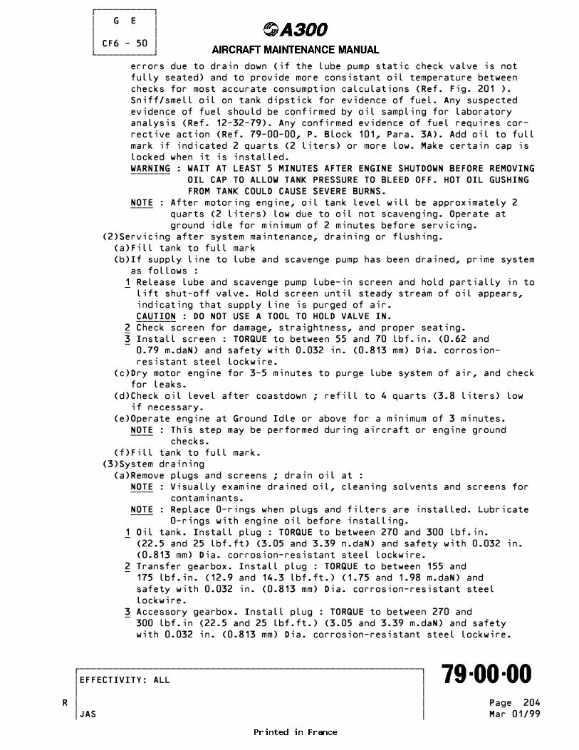
������������ � G E � � � � CF6 - 50 � ������������ errors due to drain down (if the lube pump static check valve is not fully seated) and to provide more consistant oil temperature between checks for most accurate consumption calculations (Ref. Fig. 201 ). Sniff/smell oil on tank dipstick for evidence of fuel. Any suspected evidence of fuel should be confirmed by oil sampling for laboratory analysis (Ref. 12-32-79). Any confirmed evidence of fuel requires cor- rective action (Ref. 79-00-00, P. Block 101, Para. 3A). Add oil to full mark if indicated 2 quarts (2 liters) or more low. Make certain cap is locked when it is installed. WARNING : WAIT AT LEAST 5 MINUTES AFTER ENGINE SHUTDOWN BEFORE REMOVING _______ OIL CAP TO ALLOW TANK PRESSURE TO BLEED OFF. HOT OIL GUSHING FROM TANK COULD CAUSE SEVERE BURNS. NOTE : After motoring engine, oil tank level will be approximately 2 ____ quarts (2 liters) low due to oil not scavenging. Operate at ground idle for minimum of 2 minutes before servicing. (2)Servicing after system maintenance, draining or flushing. (a)Fill tank to full mark (b)If supply line to lube and scavenge pump has been drained, prime system as follows : 1 Release lube and scavenge pump lube-in screen and hold partially in to _ lift shut-off valve. Hold screen until steady stream of oil appears, indicating that supply line is purged of air. CAUTION : DO NOT USE A TOOL TO HOLD VALVE IN. _______ 2 Check screen for damage, straightness, and proper seating. _ 3 Install screen : TORQUE to between 55 and 70 lbf.in. (0.62 and _ 0.79 m.daN) and safety with 0.032 in. (0.813 mm) Dia. corrosion- resistant steel lockwire. (c)Dry motor engine for 3-5 minutes to purge lube system of air, and check for leaks. (d)Check oil level after coastdown ; refill to 4 quarts (3.8 liters) low if necessary. (e)Operate engine at Ground Idle or above for a minimum of 3 minutes. NOTE : This step may be performed during aircraft or engine ground ____ checks. (f)Fill tank to full mark. (3)System draining (a)Remove plugs and screens ; drain oil at : NOTE : Visually examine drained oil, cleaning solvents and screens for ____ contaminants. NOTE : Replace 0-rings when plugs and filters are installed. Lubricate ____ 0-rings with engine oil before installing. 1 Oil tank. Install plug : TORQUE to between 270 and 300 lbf.in. _ (22.5 and 25 lbf.ft) (3.05 and 3.39 n.daN) and safety with 0.032 in. (0.813 mm) Dia. corrosion-resistant steel lockwire. 2 Transfer gearbox. Install plug : TORQUE to between 155 and _ 175 lbf.in. (12.9 and 14.3 lbf.ft.) (1.75 and 1.98 m.daN) and safety with 0.032 in. (0.813 mm) Dia. corrosion-resistant steel lockwire. 3 Accessory gearbox. Install plug : TORQUE to between 270 and _ 300 lbf.in (22.5 and 25 lbf.ft.) (3.05 and 3.39 m.daN) and safety with 0.032 in. (0.813 mm) Dia. corrosion-resistant steel lockwire.
�������������������������������������������������������������� �EFFECTIVITY: ALL ������������������������������������������������������������������� 79-00-00 � � � �R Page 204 � � JAS Mar 01/99

������������ � G E � � � � CF6 - 50 � ������������ 4 Lube and scavenge pump inlet screens (6). Hold lube-in screen partial- _ ly in by hand to lift shut-off valve and drain supply line. Clean screens and re-install : tighten to between 150 and 170 lbf.in. (1.69 and 1.92 m.daN) and safetywire. CAUTION : CHECK SCREEN FOR STRAIGHTNESS BEFORE RE-INSTALLATION. _______ (b)Remove filter bowl and drain lube scavenge pump filter. Clean filter element : install element and bowl into pump hand tight and safety with 0.032 in. (0.813 mm) Dia. corrosion-resistant steel lockwire. (c)Drain at scavenge oil filter and heat exchanger : 1 Remove scavenge oil filter bowl and element : clean element. _ 2 Remove bolts and disconnect heat exchanger oil outlet line at heat ex- _ changer. Gently lift scavenge filter shut-off and allow line to drain at heat exchanger. 3 Install filter element into bowl. _ NOTE : Element may be installed with either end down. ____ 4 Make certain that 0-ring is properly installed in groove in head. _ 5 Lubricate 0-ring, sealing surfaces and threads of both head and bowl _ with engine oil. 6 Install bowl by hand, or with aid of strap wrench, until bowl bottoms _ against head, and lockwire. CAUTION : USE CARE DURING BOWL INSTALLATION TO PREVENT DAMAGING 0- _______ RING. (4)System flushing (a)Drain system in accordance with paragraph C. (b)Service system in accordance with paragraph B. NOTE : Do not replace 0-rings (unless damaged) or lockwire until after ____ draining flushing oil. NOTE : Remove, clean and install B to A vent line after bearing (4R or ____ 4B) failure in CRF before engine operation. (c)Operate engine at flight idle or above for a minimum of 3 minutes and until minimum lube scavenge temperature of 65•C (149•F) is attained. NOTE : This step may be performed during aircraft or engine ground ____ checks. CAUTION : DURING RUN MONITOR ENGINE LUBE SYSTEM INSTRUMENTATION CARE- _______ FULLY. SHUT DOWN IMMEDIATELY IF DEVIATIONS FROM OPERATING LIMITS OCCUR. (d)Shut down engine. Drain system as directed in paragraph C. WARNING : WAIT AT LEAST 5 MINUTES AFTER ENGINE SHUTDOWN BEFORE REMOVING _______ OIL TANK CAP, TO ALLOW TANK PRESSURE TO BLEED OFF. HOT OIL GUSHING FROM TANK COULD CAUSE SEVERE BURNS. (e)Service system as directed in paragraph B. (5)Servicing for black oil indication CAUTION : THE PRESENCE OF BLACK OIL COULD BE AN INDICATION OF OIL _______ DETERIORATION. NOTE : Differences in oil coloration are usually found by visual ____ observation of oil during sampling or component change. (a)Check oil sample for properties as specified in paragraph 2.B.(2)(b). Acid number and viscosity will give the best indication of oil breakdown. (b)Causes for black oil indication and corrective actions are :
�������������������������������������������������������������� �EFFECTIVITY: ALL ������������������������������������������������������������������� 79-00-00 � � � �R Page 205 � � JAS Mar 01/99
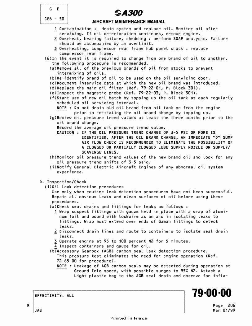
������������ � G E � � � � CF6 - 50 � ������������ 1 Contamination : drain system and replace oil. Monitor oil after _ servicing. If oil deterioration continues, remove engine. 2 Overheat, bearing failure, shedding : perform SOAP analysis. Failure _ should be accompanied by an overlimit. 3 Overheating, compressor rear frame hub panel crack : replace _ compressor rear frame. (6)In the event it is required to change from one brand of oil to another, the following procedure is recommended. (a)Remove all of the previous brands of oil from stocks to prevent intermixing of oils. (b)Re-identify brand of oil to be used on the oil servicing door. (c)Document inservice date at which the new oil brand was introduced. (d)Replace the main oil filter (Ref. 79-22-01, P. Block 301). (e)Inspect the magnetic probe (Ref. 79-22-03, P. Block 301). (f)Start use of new oil batch by topping up the oil tank at each regularly scheduled oil servicing interval. NOTE : Do not drain old oil brand from oil tank or from the engine ____ prior to initiating the oil brand change by topping up. (g)Review oil pressure trend values at least the three months prior to the oil brand change. Record the average oil pressure trend value. CAUTION : IF THE OIL PRESSURE TREND CHANGE OF 3-5 PSI OR MORE IS _______ IDENTIFIED, AFTER THE OIL BRAND CHANGE, AN IMMEDIATE TDT SUMP AIR FLOW CHECK IS RECOMMENDED TO ELIMINATE THE POSSIBILITY OF A CLOGGED OR PARTIALLY CLOGGED LUBE SUPPLY NOZZLE OR SUPPLY/ SCAVENGE LINES. (h)Monitor oil pressure trend values of the new brand oil and look for any oil pressure trend shifts of 3-5 psig. (i)Notify General Electric Aircraft Engines of any abnormal oil system experience.
D. Inspection/Check (1)Oil leak detection procedures Use only when routine leak detection procedures have not been successful. Repair all obvious leaks and clean surfaces of oil before using these procedures. (a)Check seal drains and fittings for leaks as follows : 1 Wrap suspect fittings with gauze held in place with a wrap of alumi- _ num foil and bound with lockwire as an aid in isolating leaks to fittings. Wrap must extend over ends of Gamah fittings to detect leaks. 2 Disconnect drain lines and route to containers to isolate seal drain _ leaks. 3 Operate engine at 95 to 100 percent N2 for 5 minutes. _ 4 Inspect containers and gauze for oil. _ (b)Accessory Gearbox (AGB) carbon seal leak detection procedure. This pressure test eliminates the need for engine operation (Ref. 72-65-00 for procedure). NOTE : Leakage of AGB carbon seals may be detected during operation at ____ Ground Idle speed, with possible surges to 95% N2. Attach a Light plastic bag to the AGB seal drain and observe for infla-
�������������������������������������������������������������� �EFFECTIVITY: ALL ������������������������������������������������������������������� 79-00-00 � � � �R Page 206 � � JAS Mar 01/99

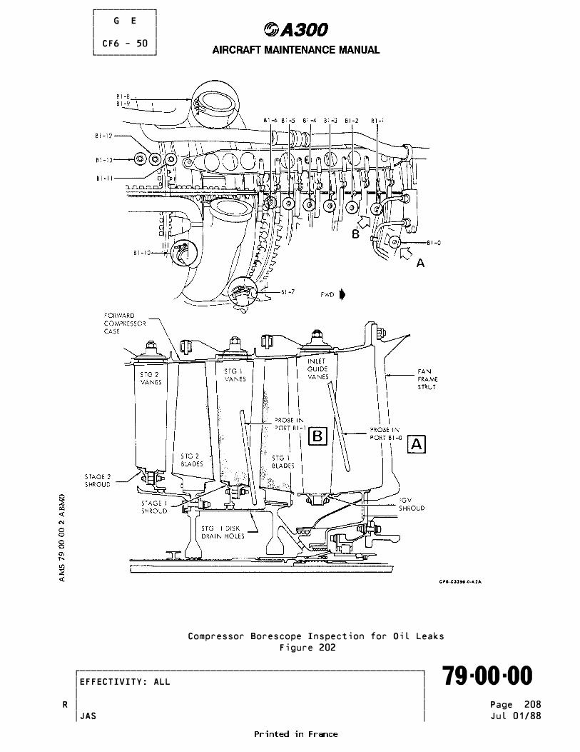
������������ � G E � � � � CF6 - 50 � ������������ tion, or attach a sensitive pressure or vacuum/pressure gage and observe for a positive reading. (c)Use of fluorescent penetrant solution : 1 If undetectable leaks still exist in the engine, leak detection fluid _ may be added to the engine lube system as follows : 2 The leak detection fluid is obtained by mixing one ounce of fluores- _R cent penetrant inspection powder (C05-023) with 2 quarts (2 liters)R of engine oil (C02-019). 3 The oil and fluorescent penetrant powder must be throughly agitated _ to ensure a proper suspension of the ZL-7 powder in the oil. 4 The 2 quarts (2 liters) of leak detection fluid is added to the en- _ gine oil tank, and the oil tank filled with engine oil (C02-019). NOTE : Before operating the engine to check for leaks, the engine ____ should be clean and thoroughly dry. Remove insulation blankets from sump vent fittings to provide an unobstructed view of the fittings. 5 The engine is operated at low speeds and then shut down. Use a black _ (ultraviolet) light to check for oil leaks. The fluorescent penetrant suspension in the oil will be fluorescent yellow when exposed to black light, thus permitting the detection and location of engine leaks. 6 As leaks are detected and repaired, all resultant fluid should be _ washed (using Material No. 10-002) from the engine and cowl and a clean, dry condition maintained. This condition is an absolute requirement to prevent masking additional leaks in the same area. 7 In order to determine the location of leaks occurring only at high en- _ gine speed, the operation should consist of start, acceleration to take-off power, then shutdown. 8 After all engine leaks have been corrected, accomplish system flushing _ to clean system. (2)Compressor borescope inspection for oil leaks (Ref. Fig. 202 ) NOTE : Borescope inspection of compressor can locate internal oil leaks, ____ indicated by oil wetting or staining. Refer to Non-Destructive Testing Manual for instruction and use of fiber light probe set and high intensity light. (a)Install fiber light probe set II in borescope port B1-0 and observe for oil wetting or staining as follows : 1 View down and forward at the 6 oLclock fan frame strut No.7 trailing _ edge. Inspect the radial aft weld bead on the strut fairing from the upper to lower extremes for oil wetting. If oil is flowing down the weld it will show a rippling effect. Observe for a puddle or oil wet- ting at the lower end of the strut. Oil wetting at the bottom of the strut will appear as a shiny oval area just aft of the strut trailing edge. 2 View aft and inspect the inlet guide vanes and stage 1 blades for oil _ wetting and/or brown oil stains. 3 Position the probe to inspect the split line area in front of the in- _ let guide vane inner shroud. NOTE : Oil wetting of the fan frame strut and/or the inlet guide va- ____ nes, and the aft core blades and vanes, may occur as a result of leakage oil from the TAT sump enclosure. The same oil wet- ting indication may also occur as result of an engine Thung
�������������������������������������������������������������� �EFFECTIVITY: ALL ������������������������������������������������������������������� 79-00-00 � � � � Page 207 � � JAS Mar 01/99
������������ � G E � � � � CF6 - 50 � ������������
Compressor Borescope Inspection for Oil Leaks Figure 202
�������������������������������������������������������������� �EFFECTIVITY: ALL ������������������������������������������������������������������� 79-00-00 � � � �R Page 208 � � JAS Jul 01/88

������������ � G E � � � � CF6 - 50 � ������������ startT or no fan rotation, without any fault in the lube sys- tem. (b)Install probe set II in borescope port B1-1 and observe for oil wetting or staining as follows : 1 Position the probe as shown in (Ref. Fig. 202 ). Rotate the core and _ inspect for oil wetting and/or brown oil stains. As the core is rota- ted, observe for oil dripping from the drain holes in the 1st stage disk. Observe for oil wetting (drops) on nuts and shroud. 2 Move the probe outward and inspect the stage 1 blades and vanes, and _ stage 2 blades for oil wetting and/or brown oil stains. NOTE : Oil wetting indications as noted in this inspection, with no ____ oil wetting of the inlet guide vanes or forward, is probably indicative of leakage through the Inlet Gearbox drive spline due to a damaged seal or a loose spline adapter retainer. (3)Lube wetted component damage detection Indications of impending lube wetted component damage can be determined through use of magnetic plugs and screens in lube and scavenge pump. If contamination is found during normal inspection of these areas, follow trouble shooting procedures to isolate cause. (4)Isolate the source of suspect material found on inspection of the Magnetic Chip Detector or Scavenge Oil filter as follows : NOTE : Collection of metal debris in lube system scavenge screens and ____ filters, or on magnetic chip detectors may indicate parts distress in oil wetted sections of engine. It is normal that some material will be collected by the MIS monitors, usually small in size and quantity. Additionally, the monitors may collect material unrelated to engine parts, such as shotpeen residue, tool fragment or machining chips. The following is a guide to MIS source isolation, identification and evaluation. (a)Check the lube and scavenge pump scavenge inlet screens. NOTE : The pump has 5 scavenge ports: Note which port is being ____ checked to avoid errors in identifying source of suspect material. Port identifications are on bottom of pump housing. (b)If source of suspect material in screens is unknows, install fault isolation magnetic plugs in each screen base and conduct an engine ground run. Inspect plugs. NOTE : Fault isolation plugs may be installed for continuous usage ; ____ however they may shield the magnetic chip detector and cause a delay of an indication of part distress by the detector. The inspection interval for the fault isolation plugs should be the same as for the magnetic chip detector if they are installed for continuous usage. (c)Using solvent (C04-001), clean oil from the suspect material. Separate the magnetic material from non-magnetic material and isolate large or unique pieces for inspection and identification. (d)If unable to identify material and attribute to a particular source/part, send the material to a qualified laboratory for spectrographic analysis. (e)If it is determined that internal (TAT, TBT, TCT, or TDT sump) bearing distress is occuring, engine operation should be discontinued and the engine removed/repaired as soon as possible. Also a lube system clean-
�������������������������������������������������������������� �EFFECTIVITY: ALL ������������������������������������������������������������������� 79-00-00 � � � �R Page 209 � � JAS Oct 01/96

������������ � G E � � � � CF6 - 50 � ������������ up per. Cleaning paragraph of Maintenance Practices is required. (5)Isolate the source of suspect material found on inspection of the pump transfer gearbox (TGB) scavenge inlet screens/fault isolation plugs as follows : (a)Presence of bearing cage rivets indicates a radial drive shaft bearing has failed. (b)Conduct a progressive removal/inspection of the Radial Drive Shaft Assy (72-62-00) and TGB assembly (72-63-00). Turn bearings by hand and observe for roughness. Check for distress material collection in the assemblies. Material collected on top of an assembly indicates distress is above that assembly. (c)Presence of this aluminum shim material indicates Inlet Gearbox (IGB) distress. (6)If a source of suspect material cannot be determined by ground run with the fault isolation plugs, put the engine Ton watchT and monitor as follows : (a)Clean or replace monitoring devices. Save residue for diagnosis. (b)Continue engine in service, providing other engine parameters do not confirm engine trouble, such as : increasing vibration, EGT, oil consumption, SOAP (Spectrometric Oil Analysis Program) results, etc... (c)Inspect the magnetic chip detector and pump scavenge inlet screens and fault isolation plugs daily or after each flight. (d)If distress is not confirmed after two consecutive days of service, return to normal monitoring practices/intervals. (7)Perform diagnosis of suspect material to determine part(s) distress and establish corrective action as recommended in the following examples : (a)Using a magnifying glass, examine material on the magnetic chip detector, pump scavenge inlet screens or fault isolation plugs. Look particularly for bearing spall material, recognizable by characteristic flake appearance. Indications of bearing distress or failure requires prompt removal of gearbox, radial driveshaft or engine. Also, a lube system clean-up is required per Cleaning paragraph of Maintenance Practices. (b)Radiographic inspect the TBT or TCT sump per Non-Destructive Test Manual. If a rivet or locking pin from the No. 4B or No. 5B bearing locknut is missing, an immediate engine removal is required. (c)An engine removal is not urgent for the following material collection : 1 Labyrinth seal rub strip, coatings such as silver-plate or Sermetal _ (spectrographic analysis to confirm is recommended). 2 Packings, such as O-rings, gaskets or omni seals. _R (8)SOAP (Spectrometric Oil Analysis Program) Troubleshooting as follows: NOTE : The operators facility or a qualified local laboratory may be ____ used for spectometric analysis of oil sample. A sample of 15 cc. minimum should be extracted from the engine oil tank fill port within 45 minutes of engine shut down, prior to adding oil. Chemically clean equipment and containers must be used for each sample extraction to prevent contamination of the samples. (a)Presence of Titanium in SOAP analysis usually indicates a condition that will progressively deteriorate such as No. 3R bearing inner race
�������������������������������������������������������������� �EFFECTIVITY: ALL ������������������������������������������������������������������� 79-00-00 � � � � Page 210 � � JAS Mar 01/00

������������ � G E � � � � CF6 - 50 � ������������ spinning on the shaft. If Titanium is present, greater than trace level (defined as 0.3 ppm) but less than 2 ppm, confirm presence by checking another sample within 50 hours. If titanium is confirmed at a level greater than 0.3 ppm, remove the engine within 20 cycles. If recheck shows Titanium below 0.3 ppm, revert to normal SOAP interval checks. If any reading of Titanium exceeds 2 ppm, confirmed by recheck, then remove engine within 20 cycles. 1 The following are SOAP results that may occur, and the probable _ related parts distress and indications : - Titanium, Iron, tungsten and nickel. Presence of these elements in a SOAP sample could indicate the No. 3R Bearing inner race is spinning on the shaft which could eventually cause HPC rubs, increase in EGT, and core vibration. - Titanium, Iron : A loose No. 1 bearing spanner nut will cause wear of the rotating oil seal due to spinning on the shaft or the No. 1 bearing inner race spinning. Titanium SOAP results may not increase however, distress may be indicated by increasing fan rotor vibes and difficulty in stabilizing or correction of fan rotor vibes. - Titanium, Aluminum, Nickel : No. 1 bearing forward housing loose (forward housing is Titanium with Aluminum-Nickel coating). If substantial amount of Aluminium is discharged into some engine oils a reaction may occur with a constituent in the oil, Quinizarin, which will dye the oil wetted parts a purple color. The dye is not harmful to parts. Aluminum SOAP results may also be accompanied by increasing fan rotor vibes and oil consumption.
(b)Immediate investigation is required for reported large (10 to 12 ppm) increase or appearance of Iron or a minor (5 to 7 ppm) increase or appearance of Iron in conjuction with an indication of copper, as follows : 1 Inspect lube system monitors : master magnetic chip detector, lube and _ scavenge pump scavenge inlet screens and scavenge oil filter. If suspect material is found investigate per MIS /Metal in Screen) procedures in preceding paragraph 2 If lube system monitors do not have suspect material, put the engine _ Ton watchT and perform the following : - Take another oil sample for SOAP analysis. - Review engine vibration, EGT, oil consumption, oil pressure data history for increasing trends. - Drain, flush and reservice the engine lube system. Reduce the interval of SOAP analysis to every TAT check. Check lube system monitors after each flight or day of operation until SOAP indication is resolved. (c)Investigate progressively increasing SOAP Iron results as follows : 1 Radiographic inspect per Non-Destructive Test manual : _ - The IGB horizontal shaft spline/NPC rotor spline adapter for excessive wear. CAUTION : WHEN THE INCREASE IN IRON IS 12 TO 15 PPM OR THE TOTAL _______ READING IS 30 PPM OR HIGHER, THE RADIOGRAPH INSPECTION MUST BE ACCOMPLISHED AT THE NEXT TAT CHECK AND EVERY FOLLOWING TAT CHECK UNTIL PROBLEM IS RESOLVED.
�������������������������������������������������������������� �EFFECTIVITY: ALL ������������������������������������������������������������������� 79-00-00 � � � �R Page 211 � � JAS Oct 01/96

������������ � G E � � � � CF6 - 50 � ������������ - The No. 3R and No. 4R bearings for excessive clearance (due to wear from bearing skidding). NOTE : An increase in core vibes may indicate bearing distress, and ____ an increase in oil comsumption and fumes in the aircraft cabin may accompany spline wear. 2 Inspect the lube system monitors : magnetic chip detector, lube and _ scavenge pump scavenge inlet screens, scavenge filter. If suspect material is found investigate per MIS (Metal in Screen) procedures in preceding paragraph. 3 If MIS troubleshooting procedures do not confirm and isolate possible _ parts distress : - Drain, flush and reservice the lube system. - Reduce the interval of SOAP analysis and monitor for repeat of increasing Iron trend. - Monitor engine vibration and oil comsumption trends. - Review secondary element SOAP results per the following paragraph. (d)Review SOAP analysis for presence of secondary elements to identify part or areas of distress : 1 Iron, Copper, Zinc : Indication of Accessory Gearbox (AGB) bearing _ distress or lube and scavenge pump bearing distress. The pump bearing distress may occur due to ingestion of material from engine parts distress, and Iron indication may be from engine part. 2 Iron, Chrome : Possible indication of gearbox parts distress. The _ gearbox bearing housing and the inlet gearbox horizontal shaft bevel gear spline are chrome plated. 3 Iron, Nickel, Chrome : Indication of distress in TBT, TCT or TDT _ sumps. These elements are the major constituents of many parts in the sumps, and shaft journals are chrome plated. 4 Aluminum : Indications of distress in No. 1 bearing aft housing, _ accessory gearbox, transfer gearbox and inlet gearbox housings and adapters, horizontal driveshaft housing and lube and scavenge pump housings. The scavenge oil filter, fuel/oil heat exchanger and oil tank also are made of aluminum but it is not expected that they would be produce particles in the oil that would be detected by SOAP.
E. Cleaning (1)Lube system cleaning after lube wetted parts failure. Clean contamination from lube system after parts failure as follows : (a)Remove scavenge tubing from area where damage originated to lube and scavenge pump. (b)Remove scavenge return tube between lube and scavenge pump and scavenge oil filter. 1 Remove master chip detector assembly (Ref. 79-22-03, P. Block 301). _ (c)Flush out removed tubes thoroughly with Material C04-002 or equivalent and swab out tube ID with clean rag. Re-install tubing. WARNING : HYDROCARBON SOLVENTS ARE FLAMMABLE AND TOXIC. AVOID PROLONGED _______ CONTACT WITH THE SKIN AND OBSERVE PRECAUTIONS AGAINST FIRE. 1 Reinstall master chip detector assembly (Ref. 79-22-03, _ P. Block 301). (d)Remove contaminated lube and scavenge pump and install replacement pump
�������������������������������������������������������������� �EFFECTIVITY: ALL ������������������������������������������������������������������� 79-00-00 � � � �R Page 212 � � JAS Oct 01/96

������������ � G E � � � � CF6 - 50 � ������������ (Ref. 79-21-01, P. Block 401). Contaminated pump must be returned to shop for disassembly inspection and cleaning per Component Maintenance Manual. Remove and inspect the supply filter and pump inlet screens to assess engine contamination. NOTE : Contamination downstream of lube and scavenge pump filter, heavy ____ accumulation of contaminants on supply filter screen, or conta- mination in pump scavenge screens other than the scavenge screen for the area in which a failure occured, may indicate a possible filter bypass condition. This may require disassembly of the en- gine for cleaning of lube tubes, lube jets, sumps, gearboxes, and bearings. (e)Remove and clean scavenge oil filter element and bowl. Re-install as- sembly. (f)If scavenge oil filter bypass is indicated or suspected, the following additional steps must be taken : 1 Remove scavenge oil filter, heat exchanger and oil tank. Return conta- _ minated parts to shop for disassembly and cleaning per Component Main- tenance Manuals. 2 Remove and clean scavenge return tube between filter and oil tank and _ lube supply tube between oil tank and lube and scavenge pump per step (3). Re-install tubing. (g)Drain and flush lube system per paragraph 3. (h)After flushing engine, remove lube and scavenge pump screens, scavenge oil filter element and magnetic plug for inspection : clean and re-ins- tall. If contamination is excessive, repeat flushing procedure as required.
F. Assemble Sleeve (Gamah) Fittings as Follows (Ref. Fig.203 and 204) (1)Examine 0-ring grooves and sleeve ID to be free of foreign material and/ or rough surfaces and sharp edges. NOTE : If either condition exists, remedy prior to 0-ring installation. ____ Use 400 grit emery paper (not a file) to smooth around the entire circumference. Use Material No.C04-003 or C04-001 to clean, making sure that grit does not remain in tubing. (2)Install new 0-rings into grooves making sure that they are not twisted or loose. Loose 0-rings would indicate a wrong size. Apply a generous coat of pe- trolatum, Material No.C02-033, to 0-rings, to lead-in chamfer and to inner diameter of sleeve. (3)Make certain that the end surfaces of the tubes are aligned by hand prior to installing sleeve over 0-rings. (Ref. Fig. 203 ) CAUTION : LOOSEN ADJACENT CLAMPS TO PERMIT ALIGNMENT BY HAND WHILE INS- _______ TALLING SLEEVE. (4)Install sleeve over first 0-ring by pushing and using a side to side motion. CAUTION : DO NOT ROTATE SLEEVE. ROTATING SLEEVE CAN CAUSE BUNCHING OF _______ 0-RING. (5)Make certain tubes are aligned and slide sleeve over second 0-ring using same side to side motion used in step F. (4). When nut can be started on sleeve, turn nut by hand until sleeve is bottomed on lip. Lockwire sleeve and nut.
�������������������������������������������������������������� �EFFECTIVITY: ALL ������������������������������������������������������������������� 79-00-00 � � � �R Page 213 � � JAS Oct 01/96

������������ � G E � � � � CF6 - 50 � ������������ CAUTION : TURN NUT ONLY, NOT SLEEVE. _______ ___ (6)Re-tighten all brackets and/or clamps previously loosened for tube alignment.
G. Re-use of Gaskets Gaskets that are constructed of aluminum with flexible, imbedded, sealing material are re-usable, provided the following limits are met. NOTE : Pre-formed packings (0-rings) are not re-useable. Lubricate and ins- ____ tall new pre-formed packing where required. (1)No nicks, cuts or gouges across sealing surfaces of sealing material. (2)Sealing material is not hard or brittle. (3)Sealing material protrudes at least 0.018 in. (0.45 mm) above metal surface. (4)No seal material extrusion or cold flow in an amount sufficient to inter- fere with or overlap onto sealing surface. NOTE : Thin Lacy sealing material that extends beyond the normal sealing ____ material configuration may be trimmed being careful not to cut or loosen the base sealing material.
H. Oil System Flow Check (1)Oil Flow Test. Using oil flow test tooling 2C6460 (or equivalent) and ap- proved engine oil, sequentially flow test the engine frames and gearboxes with oil at 135•F (57•C) and 50 psig (3.45 bars) at supply connec- tions per following table. Compare measurements to limits specified. NOTE : Use only engine oils listed Material C02-019. ____
-------------------------------------------------------------------------------- | | Flow Limits per minute | Engine Connection |-------------------------- Area |-----------------------------------| Min | Max | Supply | Scavenge |------------|------------- | | |GAL | (LIT) |GAL | (LIT) -----------------|-----------------|-----------------|----|-------|----|-------- | | | | | | Fan Frame |Frame Oil Supply |IGB Drain Plug |4.59|(17.37)|5.25|(19.87) |Fitting | | | | | Compressor Rear |Frame Oil Supply |TBT Scav. Screen |4.21|(15.93)|4.80|(18.17) Frame |Fitting |Fitting at Pump | | | | Turbine Mid |Frame Oil Supply |TCT Scav. Screen |2.59|(9.80) |3.00|(11.36) Frame |Fitting |Fitting at pump | | | | Turbine Rear |Frame Oil Supply |TDT Scav. Screen |1.04|(3.93) |1.56|(5.90) Frame |Fitting |Fitting at Pump | | | | Gearbox EMU (in- |Oil Supply B-nut |AGB and TGB |2.44|(9.23) |2.89|(10.93) cludes TGB, AGB, |at the Horiz. |Drains Plugs | | | | and Lube Pump |Fire Shield | | | | | Supply) | | | | | | Accessory G/B |Oil Supply B-nut |AGB Drain Plug |1.72|(6.51) |2.02|(7.64) (Includes Lube |at the Horiz. | | | | | Pump Supply) |Fire Seal and | | | | | |TGB Oil Supply | | | | | |capped off | | | | | Transfer G/B |TGB Oil Supply |TGB Drain Plug |1.34|(5.07) |1.65|(6.24)
�������������������������������������������������������������� �EFFECTIVITY: ALL ������������������������������������������������������������������� 79-00-00 � � � �R Page 214 � � JAS Oct 01/96

������������ � G E � � � � CF6 - 50 � ������������ -------------------------------------------------------------------------------- | | Flow Limits per minute | Engine Connection |-------------------------- Area |-----------------------------------| Min | Max | Supply | Scavenge |------------|------------- | | |GAL | (LIT) |GAL | (LIT) -----------------|-----------------|-----------------|----|-------|----|-------- |Line B-nut at the| | | | | |main oil line | | | | | | | | | | | -------------------------------------------------------------------------------
(2)Air Flow Test (a)Connect air flow test stand (2C6468) to engine areas specified in the air test table. (b)Flow test engine frames and gearboxes with air at 80•F (26.7•C) and a pressure of 30.3 psig (2.09 bars). (c)Compare measurements to limits specified in table.
-------------------------------------------------------------------------------- | Engine Connection | Flow Limits (cubic feet | | per minute) |-----------------------------------|-------------------------- Area | | Min | Max | Supply | Scavenge |------------|------------- | | | | | | -----------------|-----------------|-----------------|----|-------|----|-------- | | | | | | Fan Frame |Frame Oil Supply |IGB Drain Plug |5.88| |7.18| |Fitting | | | | | Compressor Rear |Frame Oil Supply |TBT Scav. Screen |4.28| |5.22| Frame |Fitting |Fitting at Pump | | | | Turbine Mid |Frame Oil Supply |TCT Scav. Screen |2.73| |3.33| Frame |Fitting |Fitting at pump | | | | Turbine Rear |Frame Oil Supply |TDT Scav. Screen |1.50| |2.00| Frame |Fitting |Fitting at Pump | | | | Gearbox EMU (in- |Oil Supply B-nut |AGB and TGB |2.72| |4.20| cludes TGB, AGB, |at the Horiz. |Drains Plugs | | | | and Lube Pump |Fire Shield | | | | | Supply) | | | | | | Accessory G/B |Oil Supply B-nut |AGB Drain Plug |2.50| |3.30| (Includes Lube |at the Horiz. | | | | | Pump Supply) |Fire Seal and | | | | | |TGB Oil Supply | | | | | |capped off | | | | | Transfer G/B |TGB Oil Supply |TGB Drain Plug |1.50| |2.39| |Line B-nut at the| | | | | |main oil line | | | | | | | | | | | -------------------------------------------------------------------------------
�������������������������������������������������������������� �EFFECTIVITY: ALL ������������������������������������������������������������������� 79-00-00 � � � �R Page 215 � � JAS Oct 01/96

������������ � G E � � � � CF6 - 50 � ������������
Sleeve (Gamah) Fitting Figure 203
�������������������������������������������������������������� �EFFECTIVITY: ALL ������������������������������������������������������������������� 79-00-00 � � � �R Page 216 � � JAS Oct 01/96

������������ � G E � � � � CF6 - 50 � ������������
Sleeve Assembly Figure 204
�������������������������������������������������������������� �EFFECTIVITY: ALL ������������������������������������������������������������������� 79-00-00 � � � �R Page 217 � � JAS Oct 01/96
������������ � G E � � � � CF6 - 50 � ������������ J. Close-Up (1)Make certain that working area is clean and clear of tools and miscel- laneous items of equipments. (2)Close fan cowls (Ref. 71-13-00, P. Block 301).
�������������������������������������������������������������� �EFFECTIVITY: ALL ������������������������������������������������������������������� 79-00-00 � � � �R Page 218 � � JAS Oct 01/96
������������ � G E � � � � CF6 - 50 � ������������ ENGINE OIL QUANTITY CHECK BY DIPSTICK PRIOR TO EACH FLIGHT __________________________________________________________
REFERENCE : MMEL SECTION 1-79, ITEM 1 _____________________________________ CAUTION : THIS PROCEDURE IS TO BE USED ACCORDING TO THE REQUIREMENTS OF THE _______ MMEL. WARNING : IN ORDER TO ALLOW THE OIL TO SETTLE AT ITS NORMAL LEVEL, WAIT FIVE TO _______ FIFTEEN MINUTES AFTER ENGINE SHUT DOWN BEFORE STARTING FILLING.
1. Reason for the Job __________________
A. Failure of LH (RH) engine oil quantity indicator.
2. Equipment and Materials _______________________ ------------------------------------------------------------------------------- ITEM DESIGNATION ------------------------------------------------------------------------------- A. Circuit Breaker Safety Clips Referenced Procedures - 12-13-79, P. Block 1 Replenishing-Engines - 71-13-00, P. Block 301
3. Procedure _________
A. Job Set-Up (1)Open safety and tag the circuit breakers for the appropriate engine and open fan cowl doors (Ref. 71-13-00, P. Block 301).
B. Check (1)Check oil level and top up if necessary (Ref. 12-13-79, P. Block 1).
C. Close-Up (1)Close fan cowl doors, remove safety clips and tags and close circuit breakers (Ref. 71-13-00, P. Block 301). (2)Install a temporary placard in the flight compartment to warn the aircrew that LH (RH) oil quantity indicator 3EN (4EN)is inoperative. (3)Make an entry in the aircraft technical log.
�������������������������������������������������������������� �EFFECTIVITY: ALL ������������������������������������������������������������������� 79-00-00 � � � �R Page 401 � � JAS Jan 01/88

������������ � G E � � � � CF6 - 50 � ������������ OIL FILTER CLOGGING - DAILY OR LAYOVER CHECK ____________________________________________ REFERENCE : MEL SECTION 1-79, ITEM 5 CAUTION : THIS PROCEDURE IS TO BE USED ACCORDING TO THE REQUIREMENTS OF THE MEL. _______
R 1. Oil Filter Clogging ___________________
R A. Reason for the jobR (1)Failure of oil filter clogging indicating system.
R B. Equipment and materials ------------------------------------------------------------------------------- ITEM DESIGNATION -------------------------------------------------------------------------------R (1) Circuit Breaker Safety ClipsR (2) Warning Notice Referenced Procedures - 79-22-01, P. Block 301 Scavenge Oil Filter-Servicing - 12-13-79, P. Block 1 Replenishing - Engines - 71-13-00, P. Block 301 Cowl Doors
R C. ProcedureR (1)Job set-upR (a)Open, safety and tag the circuit breakers for the appropriate engine and open fan cowl doors (Ref. 71-13-00, P. Block 301).R (2)CheckR (a)Check the filter ; if necessary, replace it (Ref. 79-22-01, P. Block 301).R (3)Close-upR (a)Perform idle leak check and service oil tank (Ref. 12-13-79, P. Block 1).R (b)Close fan cowl doors, remove safety clips and tags and close circuit breakers (Ref. 11-13-00, P. Block 301).R (c)Install a warning notice in the flight compartment to warn the aircrew that ENG1 (ENG2) OIL GLOG warning light 15EF (16EF) is inoperative.R (d)Make an entry in the aircraft technical log.
R 2. Oil Filter Clogging System (FAA Only) _____________________________________R REFERENCE : MMEL 79-30-04 (FAA Only)
R A. DeactivationR (1)Reason for the jobR CAUTION : THIS PROCEDURE IS TO BE USED ACCORDING TO THE REQUIREMENTS _______R OF THE FAA MMEL.R (a)Failure of oil filter clogging indicating circuit.R (2)Equipment and materialsR -------------------------------------------------------------------------------R ITEM DESIGNATIONR -------------------------------------------------------------------------------R (a) Protective CoversR (b) Circuit Breaker Safety ClipsR (c) Warning Notice
�������������������������������������������������������������� �EFFECTIVITY: ALL ������������������������������������������������������������������� 79-00-00 � � � � Page 402 � � JAS Mar 01/00

������������ � G E � � � � CF6 - 50 � ������������R -------------------------------------------------------------------------------R ITEM DESIGNATIONR -------------------------------------------------------------------------------R Referenced ProceduresR - 12-13-79, P. Block 1 Replenishing-EnginesR - 71-13-00, P. Block 301 Cowl DoorsR - 79-22-01, P. Block 301 Scavenge Oil FilterR - 79-22-03, P. Block 301 Magnetic PlugR - 79-35-11, P. Block 401 Oil Filter Clogging Switch
R (3)ProcedureR (a)Job set-upR 1 Open, safety and tag the circuit breakers for the appropriate _R engine and open fan cowl doors (Ref. 71-13-00, P. Block 301).R (b)Inspect chip detector to confirm absence of metallic particleR contamination (Ref. 79-22-03, P. Block 301).R (c)Check oil filter for contaminationR 1 Check filter and replace if necessary (Ref. 79-22-01, P. Block 301). _R (d)Deactivate OIL CLOG light affected.R 1 Cut and remove lockwire, then disconnect electrical connector _R P1-8065 from oil filter clogging switch S1-294. Install protectiveR cover to switch and electrical connector and stow and secureR electrical connector with adhesive tape.R (e)Close-upR 1 Perform idle leak check and service oil tank (Ref. 12-13-79, _R P. Block 1).R 2 Close fan cowl doors, remove safety clips and tags and close _R circuit breakers (Ref. 71-13-00, P. Block 301).R 3 Install a warning notice in the flight compartment to warn the _R aircrew that ENG1 (ENG2) OIL CLOG warning light 15EF (16EF) isR inoperative.R 4 Make an entry in the aircraft technical log. _
R B. ReactivationR (1)Job set-upR (a)Open, safety and tag the circuit breakers for the appropriate engineR and open fan cowl doors (Ref. 71-13-00, P. Block 301).R (2)Install electrical connector P1-8065.R (a)Remove adhesive tape and protective cover and connect electricalR connector P1-8065 to oil filter clogging switch S1-294, and wirelockR (Ref. Fig. 401 ).R (3)Close-upR (a)Troubleshoot the system.R (b)Not applicable.R (c)Test oil filter clogging indicating circuit (Ref. 79-35-11,R P. Block 401).R (d)Perform idle leak check and service oil tank (Ref. 12-13-79,R P. Block 1).R (e)Make certain that working area is clean and clear of tools andR miscellaneous items of equipment.R (f)Close fan cowl doors and remove safety clips and tags and close
�������������������������������������������������������������� �EFFECTIVITY: ALL ������������������������������������������������������������������� 79-00-00 � � � � Page 403 � � JAS Mar 01/00
������������ � G E � � � � CF6 - 50 � ������������R circuit breakers (Ref. 71-13-00, P. Block 301).R (g)Remove the warning notice in the flight compartment.
�������������������������������������������������������������� �EFFECTIVITY: ALL ������������������������������������������������������������������� 79-00-00 � � � � Page 404 � � JAS Mar 01/00

������������ � G E � � � � CF6 - 50 � ������������
Scavenge Oil Filter Clogging SwitchR Figure 401
�������������������������������������������������������������� �EFFECTIVITY: ALL ������������������������������������������������������������������� 79-00-00 � � � � Page 405 � � JAS Mar 01/00

������������ � G E � � � � CF6 - 50 � ������������ STORAGE - DESCRIPTION AND OPERATION ___________________________________
1. General _______ The engine lubricating oil is stored in a tank attached on the RH side of the engine. The lubrication system has an overall capacity of 31.7 US Quarts (30 liters). The oil tank has a useful volume of 24 US Quarts (22.7 liters). The tank can be gravity or pressure filled.
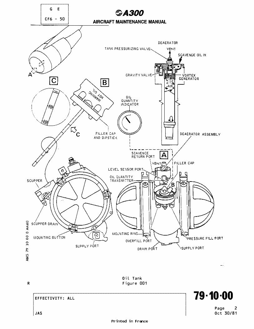
R 2. Description (Ref. Fig. 001 ) ___________ The tank is an aluminum fabrication coated with a thin layer of silicone rubber for fireproofing. The tank mounting rings are secured to the fan casing with spring loaded turnbuckles. The tank is fastened to its mounting rings through 6 vibration insulating mounting buttons. Integral with the tank are the tank pressurizing valve and de-aerator assembly. The tank has the following ports : A. Scavenge return port. B. Lube supply port. C. Vent port. D. Gravity fill port. E. Pressure fill port. F. Overfill port. G. Scupper drain. H. Drain port. I. Level sensor port. The gravity fill port has a filler cap/dipstick assembly. The cap is designed to provide an indication of an incorrect seating. A bolt-on scupper is used to collect and drain oil that has been spilled in the process of servicing the tank. Design features of the oil tank are : Capacity 24 US Quarts (22.7 liters) ; fill level Minimum oil level 6 US Quarts (5.7 liters) Tank pressure 7-9 psi (0.48-0.62 bar) above transfer gearbox vent pressure
3. Operation _________ Oil supply for the lubrication system flows from the supply port located in a sump at the bottom of the oil tank. In general terms, the tank supplies oil to the system during all flight attitudes not exceeding 30 degrees nose up or nose down and 20 degrees left or right bank with the exception that a nose down condition between 20 and 30 degrees is limited to 30 seconds. The scavenge oil contains a large amount of air because the capacity of the scavenge elements is much greater than the supply elements. This entrained air is removed with the de-aerator assembly. The de-aerator assembly is mounted inside the tank and consists of a forced vortex generator, a de- aerator and a vent port. The flow energy in the scavenge return air/oil mixture is used to form and maintain a vortex within the de-aerator by forcing the air/oil mixture through the vortex generator. The centrifugal force of the oil against the de-aerator separates the air from the oil. This air is vented into the top of the tank. A tank pressurizing valve limits the air pressure within the tank to 7-9 psi (0.48-0.62 bar) and vents excess air
�������������������������������������������������������������� �EFFECTIVITY: ALL ������������������������������������������������������������������� 79-10-00 � � � � Page 1 � � JAS Oct 30/81
������������ � G E � � � � CF6 - 50 � ������������
Oil TankR Figure 001
�������������������������������������������������������������� �EFFECTIVITY: ALL ������������������������������������������������������������������� 79-10-00 � � � � Page 2 � � JAS Oct 30/81

������������ � G E � � � � CF6 - 50 � ������������ to the transfer gearbox. During engine operation the oil level within the tank decreases from the static or full level. At 100 percent engine speed, the operating level may be 6 to 9 quarts (5.67 to 8.5 liters) lower than the full level. The decrease in oil level is termed TgulpingT and is attributed to oil that is collected on bearings sump walls, within the oil supply and scavenge lines, etc. As engine speed decreases less oil volume is captured within the engine and when the engine finally stops rotating, all of the oil has been returned to the tank except for oil lost from the system. The oil tank is drained by removing the drain plug in the oil tank drain port.
�������������������������������������������������������������� �EFFECTIVITY: ALL ������������������������������������������������������������������� 79-10-00 � � � �R Page 3 � � JAS Oct 30/81
������������ � G E � � � � CF6 - 50 � ������������ CIL TANK ASSY - MAINTENANCE PRACTICES _____________________________________
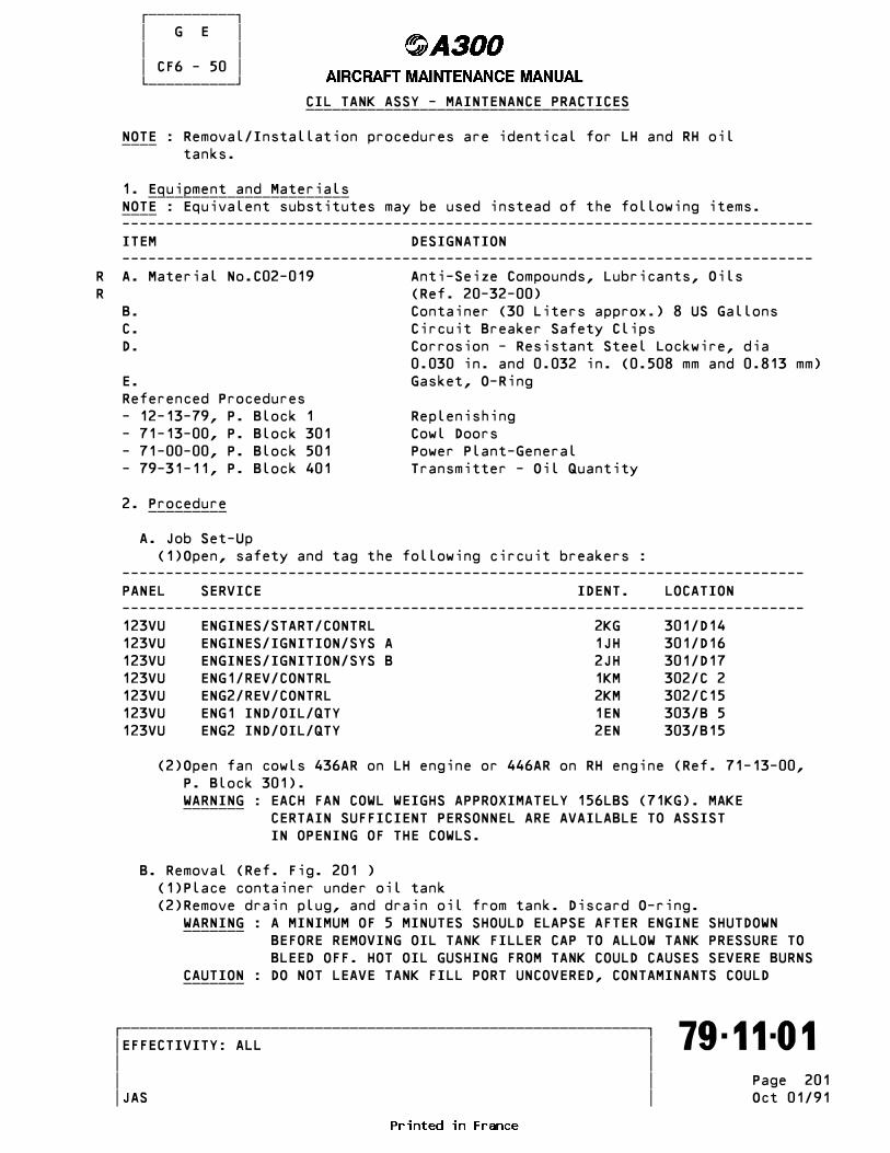
NOTE : Removal/Installation procedures are identical for LH and RH oil ____ tanks.
1. Equipment and Materials _______________________ NOTE : Equivalent substitutes may be used instead of the following items. ____ ------------------------------------------------------------------------------- ITEM DESIGNATION -------------------------------------------------------------------------------R A. Material No.C02-019 Anti-Seize Compounds, Lubricants, OilsR (Ref. 20-32-00) B. Container (30 Liters approx.) 8 US Gallons C. Circuit Breaker Safety Clips D. Corrosion - Resistant Steel Lockwire, dia 0.030 in. and 0.032 in. (0.508 mm and 0.813 mm) E. Gasket, O-Ring Referenced Procedures - 12-13-79, P. Block 1 Replenishing - 71-13-00, P. Block 301 Cowl Doors - 71-00-00, P. Block 501 Power Plant-General - 79-31-11, P. Block 401 Transmitter - Oil Quantity
2. Procedure _________
A. Job Set-Up (1)Open, safety and tag the following circuit breakers : ------------------------------------------------------------------------------ PANEL SERVICE IDENT. LOCATION ------------------------------------------------------------------------------ 123VU ENGINES/START/CONTRL 2KG 301/D14 123VU ENGINES/IGNITION/SYS A 1JH 301/D16 123VU ENGINES/IGNITION/SYS B 2JH 301/D17 123VU ENG1/REV/CONTRL 1KM 302/C 2 123VU ENG2/REV/CONTRL 2KM 302/C15 123VU ENG1 IND/OIL/QTY 1EN 303/B 5 123VU ENG2 IND/OIL/QTY 2EN 303/B15
(2)Open fan cowls 436AR on LH engine or 446AR on RH engine (Ref. 71-13-00, P. Block 301). WARNING : EACH FAN COWL WEIGHS APPROXIMATELY 156LBS (71KG). MAKE _______ CERTAIN SUFFICIENT PERSONNEL ARE AVAILABLE TO ASSIST IN OPENING OF THE COWLS.
B. Removal (Ref. Fig. 201 ) (1)Place container under oil tank (2)Remove drain plug, and drain oil from tank. Discard O-ring. WARNING : A MINIMUM OF 5 MINUTES SHOULD ELAPSE AFTER ENGINE SHUTDOWN _______ BEFORE REMOVING OIL TANK FILLER CAP TO ALLOW TANK PRESSURE TO BLEED OFF. HOT OIL GUSHING FROM TANK COULD CAUSES SEVERE BURNS CAUTION : DO NOT LEAVE TANK FILL PORT UNCOVERED, CONTAMINANTS COULD _______
�������������������������������������������������������������� �EFFECTIVITY: ALL ������������������������������������������������������������������� 79-11-01 � � � � Page 201 � � JAS Oct 01/91

������������ � G E � � � � CF6 - 50 � ������������
Oil Tank Assy Figure 201
�������������������������������������������������������������� �EFFECTIVITY: ALL ������������������������������������������������������������������� 79-11-01 � � � �R Page 202 � � JAS Oct 30/81

������������ � G E � � � � CF6 - 50 � ������������ ENTER TANK. (3)Remove scavenge oil return tube. Retain gasket. (4)Disconnect vent tube. (5)Remove oil supply tube and bracket. Retain gasket. (6)Disconnect scupper drain tube. (7)Disconnect electrical connector from oil quantity transmitter. (8)Loosen nuts on both turnbuckles and lengthen turnbuckles until tank mounting tension is released. CAUTION : DO NOT REMOVE THE SAFETY WIRE SECURING THE LARGE CENTER _______ NUTS ON THE TURNBUCKLES. (9)Remove turnbuckles from tank. (10)Remove tank. WARNING : OIL TANK WEIGHS APPROXIMATELY 27LBS (12.3KG). MAKE CERTAIN _______ TANK IS ADEQUATELY SUPPORTED WHEN REMOVING FROM ENGINE. (11)Remove oil quantity transmitter. (Ref. 79-31-11, P. Block 401). Discard O-ring. (12)Remove scupper drain union from tank. Discard O-ring. (13)Remove overfill quick-disconnect fitting and elbow from tank. Discard O-rings. (14)Remove pressure fill quick-disconnect fitting and elbow from tank. Discard O-rings. (15)If required remove deaerator from tank as follows : Remove bolts and rotate deaerator 90 degrees to permit deflector plate to pass through access opening and remove deaerator. Discard gasket.
C. Installation WARNING : MAKE CERTAIN CIRCUIT BREAKERS ARE OPEN, SAFETIED AND TAGGED _______ BEFORE ATTEMPTING MAINTENANCE PROCEDURES. INADVERTENT ENGINE START OR THRUST REVERSER OPERATION COULD RESULT IN DEATH OR SERIOUS INJURY TO PERSONNEL. (1)If deaerator was removed from tank proceed as follows : (a)Install and position new gasket on access opening flange for dearator. (b)Install deaerator into access port making sure that plate, gasket, and flange holes are aligned. (c)TORQUE bolts to between 90 and 100 lbf.in. (1.01 to 1.13 m.daN). Safety bolts with 0.032 in. (0.813 mm) dia corrosion-resistant steel lockwire. (2)Lightly lubricate new O-ring and union with engine oil, install O-ring on union, and install union in scupper drain port on tank. (3)Lightly lubricate new O-ring with engine oil, install O-ring in groove under head of overfill quick-disconnect fitting, and install elbow on fitting. (4)Lightly lubricate new O-ring with engine oil and install O-ring in second groove of overfill quick-disconnect fitting. Install fitting in overfill port of oil tank. (5)Lightly lubricate new O-ring with engine oil, install O-ring in groove under head of pressure fill quick-disconnect fitting, and install elbow on fitting. (6)Lightly lubricate new O-ring with engine oil and install O-ring in second groove of pressure fill quick disconnect fitting. Install fitting in pressure-fill port of oil tank.
�������������������������������������������������������������� �EFFECTIVITY: ALL ������������������������������������������������������������������� 79-11-01 � � � �R Page 203 � � JAS Oct 01/91
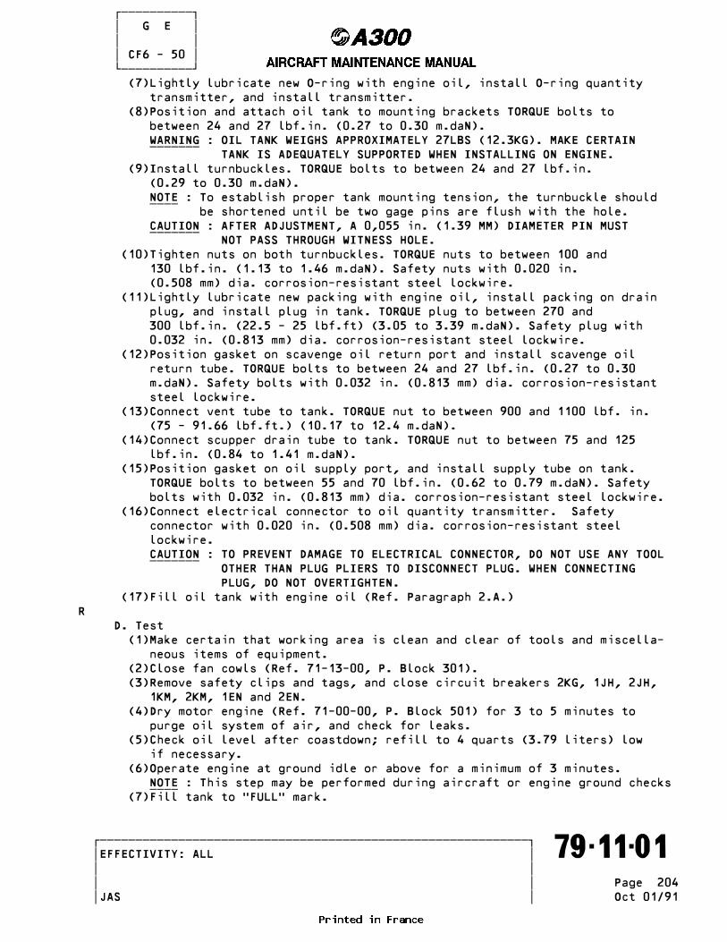
������������ � G E � � � � CF6 - 50 � ������������ (7)Lightly lubricate new O-ring with engine oil, install O-ring quantity transmitter, and install transmitter. (8)Position and attach oil tank to mounting brackets TORQUE bolts to between 24 and 27 lbf.in. (0.27 to 0.30 m.daN). WARNING : OIL TANK WEIGHS APPROXIMATELY 27LBS (12.3KG). MAKE CERTAIN _______ TANK IS ADEQUATELY SUPPORTED WHEN INSTALLING ON ENGINE. (9)Install turnbuckles. TORQUE bolts to between 24 and 27 lbf.in. (0.29 to 0.30 m.daN). NOTE : To establish proper tank mounting tension, the turnbuckle should ____ be shortened until be two gage pins are flush with the hole. CAUTION : AFTER ADJUSTMENT, A 0,055 in. (1.39 MM) DIAMETER PIN MUST _______ NOT PASS THROUGH WITNESS HOLE. (10)Tighten nuts on both turnbuckles. TORQUE nuts to between 100 and 130 lbf.in. (1.13 to 1.46 m.daN). Safety nuts with 0.020 in. (0.508 mm) dia. corrosion-resistant steel lockwire. (11)Lightly lubricate new packing with engine oil, install packing on drain plug, and install plug in tank. TORQUE plug to between 270 and 300 lbf.in. (22.5 - 25 lbf.ft) (3.05 to 3.39 m.daN). Safety plug with 0.032 in. (0.813 mm) dia. corrosion-resistant steel lockwire. (12)Position gasket on scavenge oil return port and install scavenge oil return tube. TORQUE bolts to between 24 and 27 lbf.in. (0.27 to 0.30 m.daN). Safety bolts with 0.032 in. (0.813 mm) dia. corrosion-resistant steel lockwire. (13)Connect vent tube to tank. TORQUE nut to between 900 and 1100 lbf. in. (75 - 91.66 lbf.ft.) (10.17 to 12.4 m.daN). (14)Connect scupper drain tube to tank. TORQUE nut to between 75 and 125 lbf.in. (0.84 to 1.41 m.daN). (15)Position gasket on oil supply port, and install supply tube on tank. TORQUE bolts to between 55 and 70 lbf.in. (0.62 to 0.79 m.daN). Safety bolts with 0.032 in. (0.813 mm) dia. corrosion-resistant steel lockwire. (16)Connect electrical connector to oil quantity transmitter. Safety connector with 0.020 in. (0.508 mm) dia. corrosion-resistant steel lockwire. CAUTION : TO PREVENT DAMAGE TO ELECTRICAL CONNECTOR, DO NOT USE ANY TOOL _______ OTHER THAN PLUG PLIERS TO DISCONNECT PLUG. WHEN CONNECTING PLUG, DO NOT OVERTIGHTEN. (17)Fill oil tank with engine oil (Ref. Paragraph 2.A.)R D. Test (1)Make certain that working area is clean and clear of tools and miscella- neous items of equipment. (2)Close fan cowls (Ref. 71-13-00, P. Block 301). (3)Remove safety clips and tags, and close circuit breakers 2KG, 1JH, 2JH, 1KM, 2KM, 1EN and 2EN. (4)Dry motor engine (Ref. 71-00-00, P. Block 501) for 3 to 5 minutes to purge oil system of air, and check for leaks. (5)Check oil level after coastdown; refill to 4 quarts (3.79 liters) low if necessary. (6)Operate engine at ground idle or above for a minimum of 3 minutes. NOTE : This step may be performed during aircraft or engine ground checks ____ (7)Fill tank to TFULLT mark.
�������������������������������������������������������������� �EFFECTIVITY: ALL ������������������������������������������������������������������� 79-11-01 � � � � Page 204 � � JAS Oct 01/91
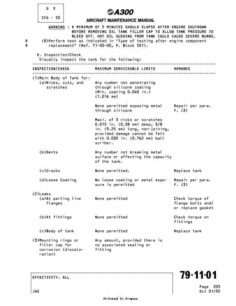
������������ � G E � � � � CF6 - 50 � ������������ WARNING : A MINIMUM OF 5 MINUTES SHOULD ELAPSE AFTER ENGINE SHUTDOWN _______ BEFORE REMOVING OIL TANK FILLER CAP TO ALLOW TANK PRESSURE TO BLEED OFF. HOT OIL GUSHING FROM TANK COULD CAUSE SEVERE BURNS.R (8)Perform test as indicated in TType of testing after engine componentR replacementT (Ref. 71-00-00, P. Block 501).
E. Inspection/Check Visually inspect the tank for the following: ------------------------------------------------------------------------------- INSPECTION/CHECK MAXIMUM SERVICEABLE LIMITS REMARKS ------------------------------------------------------------------------------- (1)Main Body of Tank for: (a)Nicks, cuts, and Any number not penetrating scratches through silicone coating (Min. coating 0.040 in.) (1.016 mm)
None permitted exposing metal Repair per para. through silicone F. (3)
Maxi. of 3 nicks or scratches 0.015 in. (0.38 mm) deep, 3/8 in. (9.25 mm) long, non-joining, provided damage cannot be felt with 0.030 in. (0.762 mm) ball scriber.
(b)Dents Any number not breaking metal surface or affecting the capacity of the tank.
(c)Cracks None permitted. Replace tank
(d)Loose Coating No loose coating or metal expo- Repair per para. sure is permitted F. (3)
(2)Leaks (a)At parting line None permitted Check torque of flanges flange bolts and/ or replace gasket
(b)At fittings None permitted Check torque on fittings
(c)Body of tank None permitted Replace tank
(3)Mounting rings or Any amount, provided there is filler cap for no associated sealing or corrosion (discolo- fitting ration)
�������������������������������������������������������������� �EFFECTIVITY: ALL ������������������������������������������������������������������� 79-11-01 � � � � Page 205 � � JAS Oct 01/92
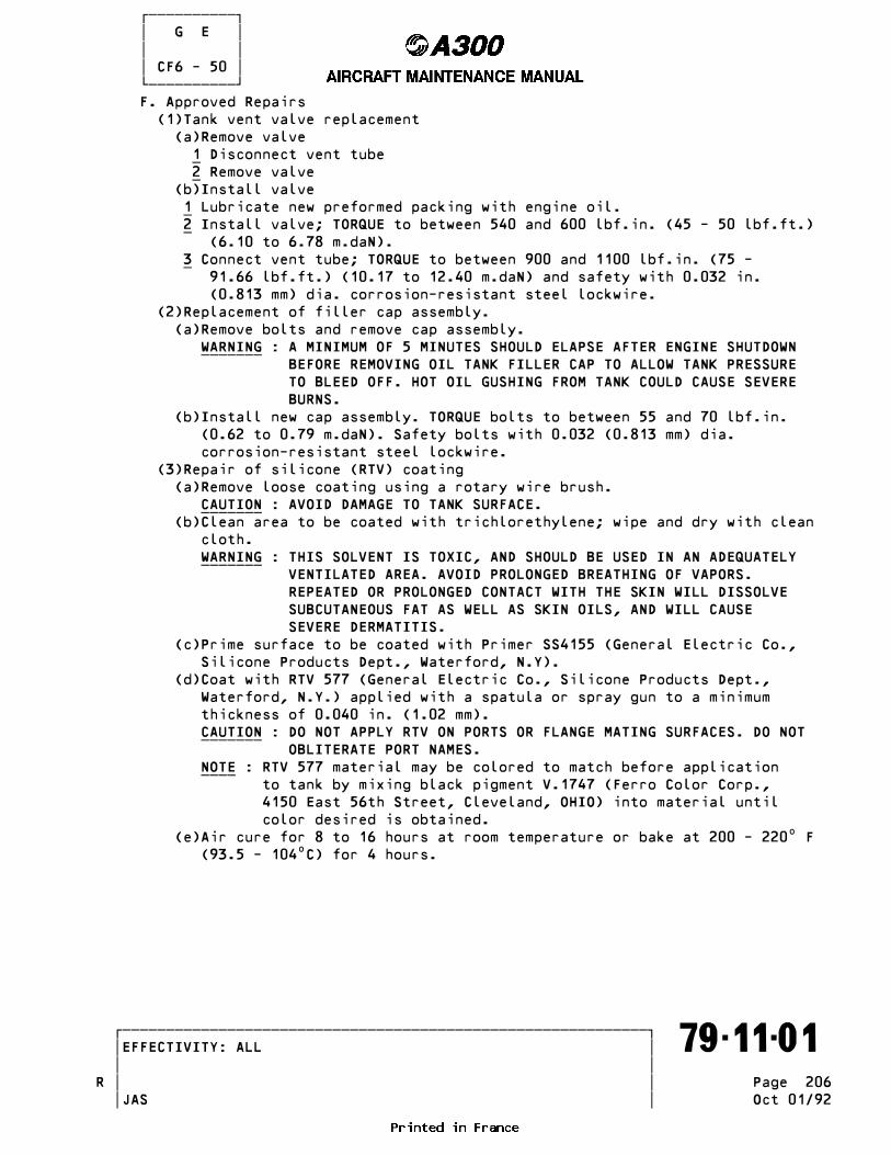
������������ � G E � � � � CF6 - 50 � ������������ F. Approved Repairs (1)Tank vent valve replacement (a)Remove valve 1 Disconnect vent tube _ 2 Remove valve _ (b)Install valve 1 Lubricate new preformed packing with engine oil. _ 2 Install valve; TORQUE to between 540 and 600 lbf.in. (45 - 50 lbf.ft.) _ (6.10 to 6.78 m.daN). 3 Connect vent tube; TORQUE to between 900 and 1100 lbf.in. (75 - _ 91.66 lbf.ft.) (10.17 to 12.40 m.daN) and safety with 0.032 in. (0.813 mm) dia. corrosion-resistant steel lockwire. (2)Replacement of filler cap assembly. (a)Remove bolts and remove cap assembly. WARNING : A MINIMUM OF 5 MINUTES SHOULD ELAPSE AFTER ENGINE SHUTDOWN _______ BEFORE REMOVING OIL TANK FILLER CAP TO ALLOW TANK PRESSURE TO BLEED OFF. HOT OIL GUSHING FROM TANK COULD CAUSE SEVERE BURNS. (b)Install new cap assembly. TORQUE bolts to between 55 and 70 lbf.in. (0.62 to 0.79 m.daN). Safety bolts with 0.032 (0.813 mm) dia. corrosion-resistant steel lockwire. (3)Repair of silicone (RTV) coating (a)Remove loose coating using a rotary wire brush. CAUTION : AVOID DAMAGE TO TANK SURFACE. _______ (b)Clean area to be coated with trichlorethylene; wipe and dry with clean cloth. WARNING : THIS SOLVENT IS TOXIC, AND SHOULD BE USED IN AN ADEQUATELY _______ VENTILATED AREA. AVOID PROLONGED BREATHING OF VAPORS. REPEATED OR PROLONGED CONTACT WITH THE SKIN WILL DISSOLVE SUBCUTANEOUS FAT AS WELL AS SKIN OILS, AND WILL CAUSE SEVERE DERMATITIS. (c)Prime surface to be coated with Primer SS4155 (General Electric Co., Silicone Products Dept., Waterford, N.Y). (d)Coat with RTV 577 (General Electric Co., Silicone Products Dept., Waterford, N.Y.) applied with a spatula or spray gun to a minimum thickness of 0.040 in. (1.02 mm). CAUTION : DO NOT APPLY RTV ON PORTS OR FLANGE MATING SURFACES. DO NOT _______ OBLITERATE PORT NAMES. NOTE : RTV 577 material may be colored to match before application ____ to tank by mixing black pigment V.1747 (Ferro Color Corp., 4150 East 56th Street, Cleveland, OHIO) into material until color desired is obtained. (e)Air cure for 8 to 16 hours at room temperature or bake at 200 - 220• F (93.5 - 104•C) for 4 hours.
�������������������������������������������������������������� �EFFECTIVITY: ALL ������������������������������������������������������������������� 79-11-01 � � � �R Page 206 � � JAS Oct 01/92

������������ � G E � � � � CF6 - 50 � ������������ DISTRIBUTION - DESCRIPTION AND OPERATION ________________________________________
1. General _______ In order to cool and lubricate the engine bearings, the gears, bevel gears, horizontal and radial shafts of the accessory gearbox, the engine is supplied with oil from a pressurized supply system. Oil distribution is achieved by an oil scavenge system, a discharge and draining system and also includes an oil seal pressurizing system.
2. Component Location __________________ (Ref. Fig. 001 ) ------------------------------------------------------------------------------ ITEM NAME PANEL ZONE ACCESS DOOR ------------------------------------------------------------------------------ B3-54 Sensor - Oil Temperature 435 435AL (Ref. 79-32-11, P. Block 401) 445 445AL S1-294 Switch - Oil Filter Clogging 435 435AL (Ref. 79-35-11, P. Block 401) 445 445AL S1-295 Switch - Low Oil Pressure 435 435AL (Ref. 79-34-11, P. Block 401) 445 445AL T2-47 Transmitter - Pressure (Oil) 435 435AL (Ref. 79-33-11, P. Block 401) 445 445AL T2-50 Transmitter - Oil Quantity 436 436AR (Ref. 79-31-11, P. Block 401) 446 446AR T2-51 Sensor - Core Speed 435 435AL (Ref. 77-12-01, P. Block 301) 445 445AL Tank - Oil 436 436AR (Ref. 79-11-01, P. Block 201) 446 446AR Dearator - Oil/Air 436 436AR (Ref. 79-11-01, P. Block 201) 446 446AR Pump Assy - Lube and Scavenge 435 435AL (Ref. 79-21-01, P. Block 401) 445 445AL Lube Filter 435 435AL (Ref. 79-21-01, P. Block 301) 445 445AL Heat Exchanger - Fuel/Oil 435 435AL (Ref. 79-22-02, P. Block 401) 445 445AL Filter - Scavenge Oil 435 435AL (Ref. 79-22-01, P. Block 301) 445 445AL Detector - Magnetic Chip 435 435AL (Ref. 79-22-03, P. Block 301) 445 445AL
�������������������������������������������������������������� �EFFECTIVITY: ALL ������������������������������������������������������������������� 79-20-00 � � � �R Page 1 � � JAS Jan 01/88

������������ � G E � � � � CF6 - 50 � ������������
Component Location Figure 001
�������������������������������������������������������������� �EFFECTIVITY: ALL ������������������������������������������������������������������� 79-20-00 � � � �R Page 2 � � JAS Oct 30/81
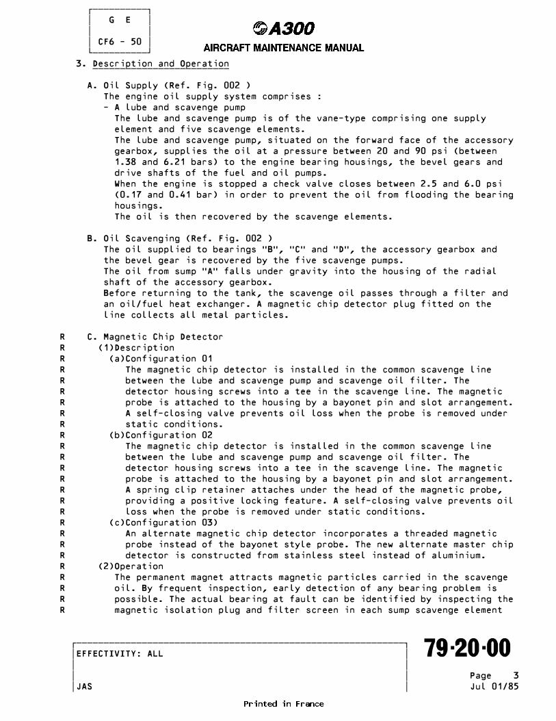
������������ � G E � � � � CF6 - 50 � ������������ 3. Description and Operation _________________________
A. Oil Supply (Ref. Fig. 002 ) The engine oil supply system comprises : - A lube and scavenge pump The lube and scavenge pump is of the vane-type comprising one supply element and five scavenge elements. The lube and scavenge pump, situated on the forward face of the accessory gearbox, supplies the oil at a pressure between 20 and 90 psi (between 1.38 and 6.21 bars) to the engine bearing housings, the bevel gears and drive shafts of the fuel and oil pumps. When the engine is stopped a check valve closes between 2.5 and 6.0 psi (0.17 and 0.41 bar) in order to prevent the oil from flooding the bearing housings. The oil is then recovered by the scavenge elements.
B. Oil Scavenging (Ref. Fig. 002 ) The oil supplied to bearings TBT, TCT and TDT, the accessory gearbox and the bevel gear is recovered by the five scavenge pumps. The oil from sump TAT falls under gravity into the housing of the radial shaft of the accessory gearbox. Before returning to the tank, the scavenge oil passes through a filter and an oil/fuel heat exchanger. A magnetic chip detector plug fitted on the line collects all metal particles.
R C. Magnetic Chip DetectorR (1)DescriptionR (a)Configuration 01R The magnetic chip detector is installed in the common scavenge lineR between the lube and scavenge pump and scavenge oil filter. TheR detector housing screws into a tee in the scavenge line. The magneticR probe is attached to the housing by a bayonet pin and slot arrangement.R A self-closing valve prevents oil loss when the probe is removed underR static conditions.R (b)Configuration 02R The magnetic chip detector is installed in the common scavenge lineR between the lube and scavenge pump and scavenge oil filter. TheR detector housing screws into a tee in the scavenge line. The magneticR probe is attached to the housing by a bayonet pin and slot arrangement.R A spring clip retainer attaches under the head of the magnetic probe,R providing a positive locking feature. A self-closing valve prevents oilR loss when the probe is removed under static conditions.R (c)Configuration 03)R An alternate magnetic chip detector incorporates a threaded magneticR probe instead of the bayonet style probe. The new alternate master chipR detector is constructed from stainless steel instead of aluminium.R (2)OperationR The permanent magnet attracts magnetic particles carried in the scavengeR oil. By frequent inspection, early detection of any bearing problem isR possible. The actual bearing at fault can be identified by inspecting theR magnetic isolation plug and filter screen in each sump scavenge element
�������������������������������������������������������������� �EFFECTIVITY: ALL ������������������������������������������������������������������� 79-20-00 � � � � Page 3 � � JAS Jul 01/85
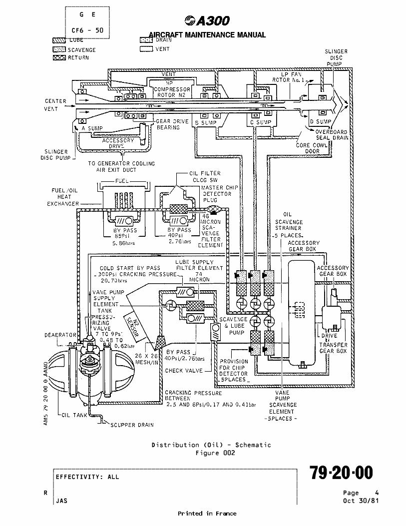
������������ � G E � � � � CF6 - 50 � ������������
Distribution (Oil) - Schematic Figure 002
�������������������������������������������������������������� �EFFECTIVITY: ALL ������������������������������������������������������������������� 79-20-00 � � � �R Page 4 � � JAS Oct 30/81

������������ � G E � � � � CF6 - 50 � ������������R of the lube and scavenge pump. - a magnetic chip detector plug may be installed on each of the five scavenge pumps.
D. Scavenge Oil Filter The filter element is housed in a filter bowl attached to one of the fan case supports at approximately 7 OLclock.
4. Lube and Scavenge Pump ______________________
A. Description (Ref. Fig. 003 ) The lube and scavenge pump is a vane type pump containing one supply element and 5 scavenge elements. Integral with the pump are inlet screens for each element, a lube supply filter with relief valve, a check valve and a cold start bypass valve. A mounting pad is located on the forward end of the pump to mount and drive the core speed (N2) sensor.
B. Operation Oil flows from the oil tank into the supply element through the removable, non-bypassing 26-mesh inlet screen. Output of the supply element then flows through the 74-micron (nominal) size, cleanable/re-usable supply filter. Total lube supply flow will bypass around the filter through the relief valve in the event that filter pressure differential exceeds 40 psid. (2.76 bars). A cold start relief valve is located in the supply element discharge and will crack when the differential pressure across the valve exceeds 300 psid (20.7 bars). The oil is returned to the supply inlet. The full flow pressure drop across the valve is 400 psid (27.6 bars), the valve reseats at 275 psid (18.97 bars). One scavenge element removes oil from the accessory gearbox and one removes oil from the transfer gearbox. Transfer gearbox oil includes scavenge oil from TAT sump which flows down the radial drive-shaft housing. The 3 remaining elements are used to scavenge the TBT, TCT and TDT sumps. Each element has a removable 26-mesh inlet screen ; additionally the scavenge inlet screens have provisions for installation of 5 magnetic chip detectors. The lube element screen also provides a service shut-off valve to permit screen removal for inspection without oil tank drainage. The lube and scavenge pump also supplies positive drive spline lubricating oil via an orifice in the drive spline
5. Scavenge Oil Filter ___________________
A. Description (Ref. Fig. 004 ) The scavenge oil filter contains a full-flow, removable, cleanable, stacked-disk-type element. A Belvalve relief valve allows the scavenge oil to bypass the element if the pressure-drop across the element exceeds 40 psid (2.76 bars). An automatic check valve is provided in the filter discharge to prevent system drainage when the filter bowl is removed. Design features of the filter are : Rated flow 16 gpm (60.56 liters) Particle removal 46 microns nominal
�������������������������������������������������������������� �EFFECTIVITY: ALL ������������������������������������������������������������������� 79-20-00 � � � � Page 5 � � JAS Jul 01/85
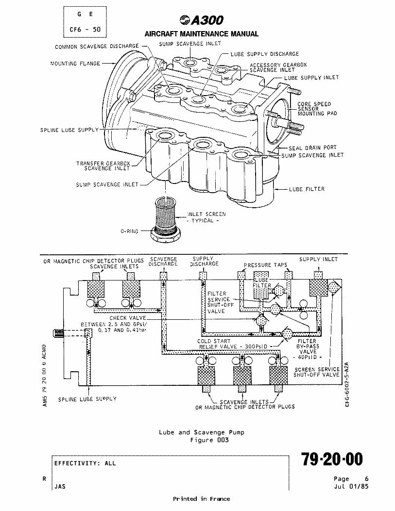
������������ � G E � � � � CF6 - 50 � ������������
Lube and Scavenge Pump Figure 003
�������������������������������������������������������������� �EFFECTIVITY: ALL ������������������������������������������������������������������� 79-20-00 � � � �R Page 6 � � JAS Jul 01/85

������������ � G E � � � � CF6 - 50 � ������������ Pressure drop 14 psi (0.96 bars) maximum with clean element Relief valve 40 psid (2.76 bars) minimum bypass cracking pressure
B. Operation Total scavenge oil from the lube and scavenge pump enters the filter inlet port and flows through the element from the outside to inside direction. Oil then flows through the normally open check valve and out of the discharge port. Pressure taps are provided in the filter body casing to permit measurement of filter element differential pressure.
6. Fuel Oil Heat Exchanger _______________________
A. Description (Ref. Fig. 005 ) The fuel/oil heat exchanger is attached to the fuel pump. The fuel/oil heat exchanger is a cylindrical, lightweight, aluminium, dual- function accessory. The heat exchanger is of shell and tube construction and consists of a large number of small side-by-side tubes brazed to header plates at each end. The shell encloses the tube bundle and is also joined to the header plate. The 2 functions of the heat exchanger are : - to heat the fuel above 35•F (2•C) to prevent fuel system icing, - to cool engine lubricating oil.
B. Operation Fuel flows from the fuel pump into the heat exchanger and through internal tubing where the fuel absorbs heat from the hot engine lubricating oil. The heated fuel then flows back into the pump. Engine scavenge oil flows into the exchanger through the oil inlet port and circulates around the fuel tubes where it is cooled by heat transfer to the fuel. The exchanger is constructed internally so that the oil flows across the tubes a total of 6 passes and the fuel in 2 passes. The cooled oil flows out of the exchanger to the oil tank. During cold weather starting, excessive pressure drop would occur if the cold viscous oil were forced to flow across the tubing in the heat exchanger. This pressure drop would result in high scavenge oil pressure. To avoid this high pressure drop, the bypass valve, which opens at 85 psid (5.86 bars), will cause the oil to bypass the heat exchanger until the oil warms sufficiently to drop the pressure and again establish normal flow.
7. Lubrication and Pressurization of the Oil Seals _______________________________________________ Each bearing is protected against leaks by an oil seal pressurised by air bled off at the level of the LP compressor discharge. A. Lubrication (Ref. Fig. 006 ) The oil from the lube pump is fed to the bearings of the engine main shaft Sump TAT receives 5.29 gpm (20 l/mn) Sump TBT receives 4.88 gpm (18.5 l/mn) Sump TCT receives 2.53 gpm (9.57 l/mn) Sump TDT receives 1.15 gpm (4.35 l/mn)
B. Pressurization of the oil seal - sump TAT
�������������������������������������������������������������� �EFFECTIVITY: ALL ������������������������������������������������������������������� 79-20-00 � � � �R Page 7 � � JAS Jul 01/85

������������ � G E � � � � CF6 - 50 � ������������
Scavenge Oil Filter Figure 004
�������������������������������������������������������������� �EFFECTIVITY: ALL ������������������������������������������������������������������� 79-20-00 � � � �R Page 8 � � JAS Jul 01/85

������������ � G E � � � � CF6 - 50 � ������������
Fuel/Oil Heat Exchanger Figure 005
�������������������������������������������������������������� �EFFECTIVITY: ALL ������������������������������������������������������������������� 79-20-00 � � � �R Page 9 � � JAS Oct 30/81
������������ � G E � � � � CF6 - 50 � ������������ The sump TAT oil seal is pressurized by the air coming from the core inner wall of the LP compressor discharge casing.
C. Pressurization of the Oil Seals - sump TBT and TCT The oil seals of sumps TBT and TCT are pressurized by air from the core outer wall of the LP compressor discharge casing. The air circulates through two pipes attached to the compressor casing before arriving at the oil seals.
D. Pressurization of the Oil Seal - sump TDT The sump TDT oil seal is pressurized by turbine discharge air. Sump TDT is not vented; the pressure differential required to prevent oil leaking through the seal is maintained by extracting the air by means of the scavenge pump.
8. Sump Air Pressure Discharge ___________________________ Each of the engine sumps except sump TDT are vented to atmosphere by evacuating the air which penetrates through the oil seals.
A. Venting of sump TAT The air is vented by means of a distributor disk in the fan spinner which blows the air down the interior of the main shaft and vents it through the center body of the exhaust nozzle.
B. Venting of sump TBT The air is vented through an external pipe into sump TAT.
C. Venting of sump TCT Sump TCT is vented into the Tlow pressureT chamber of the turbine mid- frame, through the space between the intermediate shaft and the rear shaft of the high pressure turbine, then vented to the atmosphere through the center body of the exhaust nozzle.
D. Venting of Sump TDT Sump TDT is not vented to the atmosphere. The air from the oil seal, together with the oil, is driven by the scavenge pump to the oil/air deaerator in the tank.
9. Drainage of the Oil Seals _________________________ Each oil seal is, in principle, leak-proof; but a drain is provided in each sump in order to vent any leaks from the oil seals.
A. Drainage of Sump TAT The drain pipes of sump TAT discharges through the generator cooling air exit duct located at the lower part of the RH fan case.
B. Drainage of sumps TBT and TCT The drain pipes of sumps TBT and TCT are arranged to discharge at T7 OLclockT at the lower part of the core cowl.
C. Drainage of sump TDT The drain pipe of sump TDT discharges directly into the exhaust nozzle.
�������������������������������������������������������������� �EFFECTIVITY: ALL ������������������������������������������������������������������� 79-20-00 � � � �R Page 10 � � JAS Jul 01/85
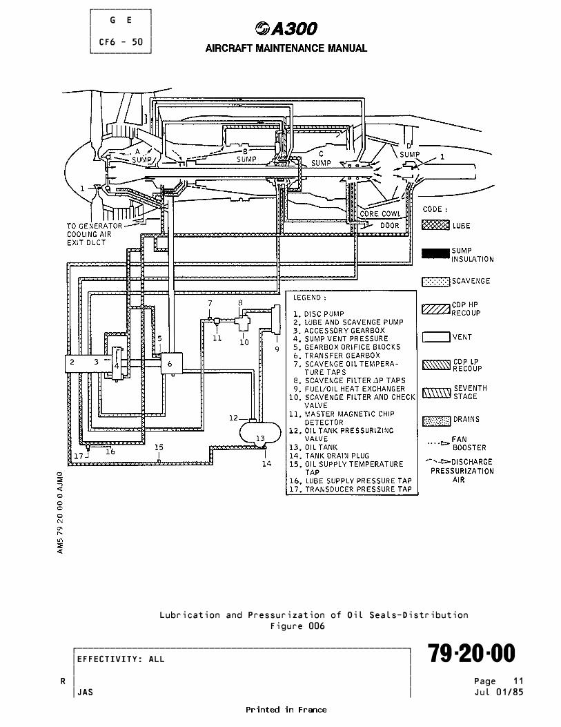
������������ � G E � � � � CF6 - 50 � ������������
Lubrication and Pressurization of Oil Seals-Distribution Figure 006
�������������������������������������������������������������� �EFFECTIVITY: ALL ������������������������������������������������������������������� 79-20-00 � � � �R Page 11 � � JAS Jul 01/85
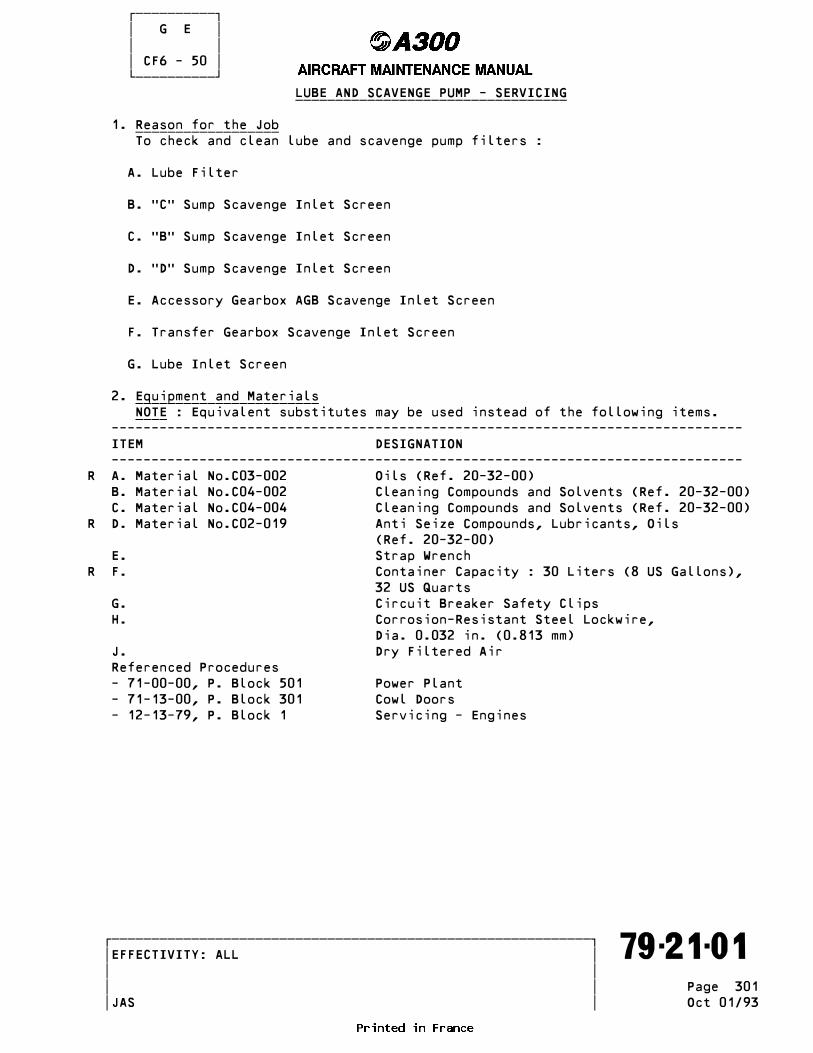
������������ � G E � � � � CF6 - 50 � ������������ LUBE AND SCAVENGE PUMP - SERVICING __________________________________
1. Reason for the Job __________________ To check and clean lube and scavenge pump filters :
A. Lube Filter
B. TCT Sump Scavenge Inlet Screen
C. TBT Sump Scavenge Inlet Screen
D. TDT Sump Scavenge Inlet Screen
E. Accessory Gearbox AGB Scavenge Inlet Screen
F. Transfer Gearbox Scavenge Inlet Screen
G. Lube Inlet Screen
2. Equipment and Materials _______________________ NOTE : Equivalent substitutes may be used instead of the following items. ____ ------------------------------------------------------------------------------- ITEM DESIGNATION -------------------------------------------------------------------------------R A. Material No.C03-002 Oils (Ref. 20-32-00) B. Material No.C04-002 Cleaning Compounds and Solvents (Ref. 20-32-00) C. Material No.C04-004 Cleaning Compounds and Solvents (Ref. 20-32-00)R D. Material No.C02-019 Anti Seize Compounds, Lubricants, Oils (Ref. 20-32-00) E. Strap WrenchR F. Container Capacity : 30 Liters (8 US Gallons), 32 US Quarts G. Circuit Breaker Safety Clips H. Corrosion-Resistant Steel Lockwire, Dia. 0.032 in. (0.813 mm) J. Dry Filtered Air Referenced Procedures - 71-00-00, P. Block 501 Power Plant - 71-13-00, P. Block 301 Cowl Doors - 12-13-79, P. Block 1 Servicing - Engines
�������������������������������������������������������������� �EFFECTIVITY: ALL ������������������������������������������������������������������� 79-21-01 � � � � Page 301 � � JAS Oct 01/93

������������ � G E � � � � CF6 - 50 � ������������ 3. Procedure _________
A. Job Set-Up (1)Open, safety and tag the following circuit breakers for the appropriate engine and open engine cowls (Ref. 71-13-00, P. Block 301). (2)Place container under lube and scavenge pump.
R B. Lube Filter Removal/Installation (Ref. Fig. 301 ) (1)Removal. (a)Remove filter bowl using strap wrench. (b)Remove and discard preformed packing from groove in bowl. (c)Remove filter element in bowl. (2)Ultrasonic Cleaning (Preferred Method). WARNING : PERFORM THIS OPERATION IN AN APPROVED CLEANING CABINET _______ OR WELL VENTILATED AREA. TAKE PRECAUTIONS TO MINIMIZE FIRE HAZARDS OR PREVENT INHALATION OF VAPORS. REPEATED OR PRO- LONGED CONTACT OF SOME CLEANING MATERIALS WITH THE SKIN WILL REMOVE SKIN OILS AND MAY CAUSE SEVERE DERMATITIS. Note : Filter must be checked for excessive residue before cleaning. ____ (a)Ultrasonically clean the filter for 10 to 20 minutes using solvent C04-004. Suspend vertically to permit loosened dirt to fall out. Operate at 40 K.C. (Kilocycle) with 30 watts output per square foot of active wall. (b)Brush the inside and outside of element with a stiff brush while im- mersed in solvent C04-002. NOTE : Do not use a wire brush. ____ (c)Ultrasonically clean filter elements for 3 to 5 minutes using solvent C04-004. Suspend element vertically. (d)Rinse filter in running warm water. (e)Oven dry at 200• F (93• C) or less, or air dry in clean protected area. CAUTION : DO NOT USE CONVENTIONAL SHOP AIR. IT USUALLY CONTAINS _______ DIRT, WATER AND OIL. (f)Light filter inside and examine filter using 10-power glass. If contaminants are still present, repeat cleaning process. (3)Immersion Cleaning (Alternate Method). WARNING : PERFORM THIS OPERATION IN AN APPROVED CLEANING CABINET _______ OR WELL VENTILATED AREA. TAKE PRECAUTIONS TO MINIMIZE FIRE HAZARDS AND PREVENT INHALATION OF VAPORS. REPEATED OR PROLON- GED CONTACT OF SOME CLEANING MATERIALS WITH THE SKIN WILL REMOVE SKIN OILS AND MAY CAUSE SEVERE DERMATITIS. (a)Immerse filter in solvent C04-002 and clean using a stiff brush. (b)Back-flush with solvent. (c)Back-flush with clean filtered compressed air. CAUTION : DO NOT USE CONVENTIONAL SHOP AIR. IT USUALLY CONTAINS _______ DIRT, WATER AND OIL. (d)Light filter inside and examine filter using 10-power glass. If conta- minants are still present, repeat cleaning process. (4)Installation. (a)Place clean filter element in bowl. NOTE : Install new element with open end up. ____
�������������������������������������������������������������� �EFFECTIVITY: ALL ������������������������������������������������������������������� 79-21-01 � � � � Page 302 � � JAS Oct 01/93

������������ � G E � � � � CF6 - 50 � ������������
Lube Filter - Config 01 - (Sheet 1/3)R Figure 301
�������������������������������������������������������������� �EFFECTIVITY: ALL ������������������������������������������������������������������� 79-21-01 � � � � Page 303 � � JAS Oct 01/93
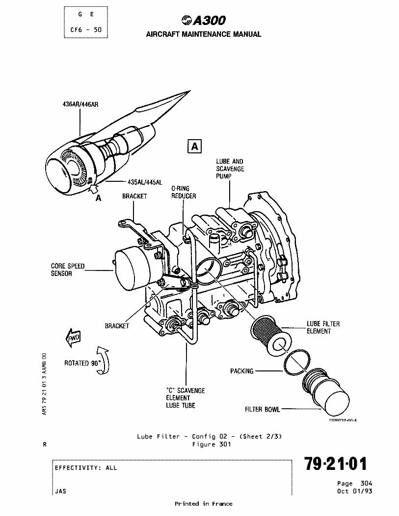
������������ � G E � � � � CF6 - 50 � ������������
Lube Filter - Config 02 - (Sheet 2/3)R Figure 301
�������������������������������������������������������������� �EFFECTIVITY: ALL ������������������������������������������������������������������� 79-21-01 � � � � Page 304 � � JAS Oct 01/93

������������ � G E � � � � CF6 - 50 � ������������
Lube Filter - Config 03 - (Sheet 3/3)R Figure 301
�������������������������������������������������������������� �EFFECTIVITY: ALL ������������������������������������������������������������������� 79-21-01 � � � � Page 305 � � JAS Oct 01/93

������������ � G E � � � � CF6 - 50 � ������������ (b)Lubricate new preformed packing and sealing surfaces of filter bowl and housing with engine oil. (c)Install preformed packing in groove in filter bowl and install bowl. (d)Turn bowl hand tight and safety with 0.032 in. (0.813 mm) dia. cor- rosion-resistant steel lockwire.
R C. Inlet Screen Removal/Installation (Configurations 01 and 03)R (Ref. Fig. 302 ) (sheets 1/3 and 3/3)
(1)Removal. NOTE : Six 26-mesh screens are mounted in lube and scavenge pump inlet ____R ports at different locations. The size of screens differ as ind- cated : ------------------------------------------------------------------------------- LOCATION DIA (INCH) LENGTH (INCH) ------------------------------------------------------------------------------- - TC SumpT scavenge inlet screen 7/8 (22.2 mm) 1 7/8 (47.6 mm) - TB SumpT scavenge inlet screen 7/8 (22.2 mm) 1 7/8 (47.6 mm) - Transfer gearbox scavenge inlet 7/8 (22.2 mm) 1 7/8 (47.6 mm) screen - TD SumpT scavenge inlet screen 5/8 (15.9 mm) 1 7/8 (47.6 mm) - Accessory gearbox scavenge inlet 5/8 (15.9 mm) 1 7/8 (47.6 mm) screenR - Lube inlet screen 1.0 (25.4 mm) 1 1/2 (38.1 mm)
NOTE : Removal/installation procedures are identical for supply inlet ____ screen and the five scavenge inlet screens of lube and scavenge pump. (a)Remove applicable screen assembly from the underside of the pump. CAUTION : USE SOCKET WRENCHES TO MINIMIZE HEXFLAT DAMAGE. _______ NOTE : The lube supply inlet port incorporates a shut-off valve which ____ prevents oil system drainage when the screen is removed. To minimize excessive oil drainage, remove the screen assembly quickly after thread disengagement. (2)Inlet Screen Cleaning. (a)Clean screen by sloshing in solvent C04-002. (b)Remove stubborn deposits using a stiff-bristle brush.R NOTE : Do not use a wire brush. ____ (3)Installation. (a)Inspect screen for damage, straightness and proper seating. (b)Lubricate O-ring with engine oil and install screen. TORQUE to between 150 and 170 lbf.in. (1.69 and 1.92 m.daN). Safety with 0.032 in. (0.813 mm) dia. corrosion-resistant steel lockwire. CAUTION : USE SOCKET WRENCHES TO MINIMIZE HEXFLAT DAMAGE. _______
R D. Inlet Screen Removal/Installation (Configuration 02)R (Ref. Fig. 302 ) (Sheet 2/3)R (1)Removal.R NOTE : Six 26-mesh screens are mounted in lube and scavenge pump inlet ____R ports at different locations. The size of screens differ asR indicated.
�������������������������������������������������������������� �EFFECTIVITY: ALL ������������������������������������������������������������������� 79-21-01 � � � � Page 306 � � JAS Oct 01/93

������������ � G E � � � � CF6 - 50 � ������������
Typical Inlet Screen - Config 01 - (Sheet 1/3)R Figure 302
�������������������������������������������������������������� �EFFECTIVITY: ALL ������������������������������������������������������������������� 79-21-01 � � � � Page 307 � � JAS Oct 01/93

������������ � G E � � � � CF6 - 50 � ������������
Typical Inlet Screen - Config 02 - (Sheet 2/3)R Figure 302
�������������������������������������������������������������� �EFFECTIVITY: ALL ������������������������������������������������������������������� 79-21-01 � � � � Page 308 � � JAS Oct 01/93
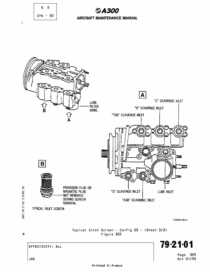
������������ � G E � � � � CF6 - 50 � ������������
Typical Inlet Screen - Config 03 - (Sheet 3/3)R Figure 302
�������������������������������������������������������������� �EFFECTIVITY: ALL ������������������������������������������������������������������� 79-21-01 � � � � Page 309 � � JAS Oct 01/93

������������ � G E � � � � CF6 - 50 � ������������R --------------------------------------------------------------------------------R LOCATION DIA (INCH) LENGTH (INCH)R --------------------------------------------------------------------------------R - TC SumpT scavenge inlet screen 7/8 (22.2 mm) 1 7/8 (47.6 mm)R - TB SumpT scavenge inlet screen 7/8 (22.2 mm) 1 7/8 (47.6 mm)R - Transfer gearbox scavenge inlet 7/8 (22.2 mm) 1 7/8 (47.6 mm)R screenR - TD SumpT scavenge inlet screen 5/8 (15.9 mm) 1 7/8 (47.6 mm)R - Accessory gearbox scavenge inlet 5/8 (15.9 mm) 1 7/8 (47.6 mm)R screenR - Lube inlet screen 1.0 (25 mm) 1 1/2 (38.1 mm)
R (a)The TCT scavenge inlet of the lube and scavenge pump has an inletR tube which is removed as follows :R - Remove the nut, washer, and bolt from the clamp that secures theR inlet tube to the bracketR - Remove the inlet tube from the TCT scavenge inlet of the lube andR scavenge pumpR - Remove the inlet tube from the oil filter on the lube and scavengeR pump.R (b)The removal/installation procedures are identical for the supply inletR screen and four scavenge inlet screens of the lube and scavenge pump.R (c)Remove applicable screen assembly from the underside of the pump.R CAUTION : USE SOCKET WRENCHES TO MINIMIZE HEXFLAT DAMAGE. _______R NOTE : The lube supply inlet port incorporates a shut-off valve ____R which prevents oil system drainage when the screen is removed.R To minimize excessive oil drainage, remove the screen assemblyR quickly after thread disengagement.R (2)Inlet Screen Cleaning.R (a)Clean screen by sloshing in solvent C04-002.R (b)Remove stubborn deposits using a stiff-bristle brush.R NOTE : Do not use a wire brush. ____R (3)InstallationR (a)Inspect screen for damage, straight mesh, and proper seating.R (b)Lubricate O-ring with engine oil and install screen. TORQUE toR between 150 and 170 lbf.in. (1.69 and 1.92 m.daN). Safety withR 0.032 in. (0.81 mm) dia. corrosion-resistant steel lockwire.R (4)Install the inlet tube as follows :R (a)Install the TCT scavenge end of the lube tube to the TCT scavenge inletR of the lube and scavenge pump.R (b)Install the oil filter end of the lube tube to the oil filter on theR lube and scavenge pump.R (c)TORQUE the B-nuts of the inlet tube to between 270 and 300 lbf.in.R (3.05 and 3.39 m.daN).R (d)Secure the lube tube to the clamp with bolt, washer and nut.R (e)TORQUE the nut to between 33 and 37 lbf.in. (0.37 and 0.42 m.daN).
R E. Plug (Magnetic Fault Isolation Provision) Removal/Installation NOTE : The blanking plugs fitted to the 5 scavenge inlet screens can be ____ removed and replaced by magnetic plugs to check return lines for metal particles.
�������������������������������������������������������������� �EFFECTIVITY: ALL ������������������������������������������������������������������� 79-21-01 � � � � Page 310 � � JAS Oct 01/93

������������ � G E � � � � CF6 - 50 � ������������ (1)Removal. (a)Remove plug and discard O-ring. (2)Installation. NOTE : Installation of the TCT sump scavenge element lube tube pro- ____ hibits use of the magnetic chip detector. (a)Check plug (magnetic plug) for cleanliness CAUTION : INSTALLATION OF THE PLUG (MAGNETIC PLUG) WITHOUT AN O-RING _______ CAN RESULT IN EXCESSIVE OIL LOSS DURING ENGINE OPERATION, WITH POSSIBLE ENGINE FAILURE. (b)Lubricate new O-ring with engine oil (C02-019) and install on plug (magnetic plug). NOTE : When removal of magnetic probe is performed where new O-ring(s) ____ may not be available, existing O-rings may be reused provided O-ring inspection confirms part serviceability. (c)Install plug (magnetic plug). TORQUE to between 75 and 85 lbf. in. (0.84 and 0.96 m.daN) and safety with 0.032 in. (0.813 mm) dia. corrosion-resistant steel lockwire.
CAUTION : DURING REMOVAL/INSTALLATION OF THE PLUG (MAGNETIC PLUG), USE _______ ONE WRENCH TO HOLD THE SCAVENGE SCREEN STATIONARY WHILE APPLYING TORQUE TO THE PLUG (MAGNETIC PLUG).
R F. Close-Up and Test (1)Remove tools, equipment, loose hardware, spilled fluid and debris from maintenance area. (2)Close fan cowls (Ref. 71-13-00, P. Block 301). (3)Remove safety clips and tags, and close circuit breakers 1JH, 2JH, 2KG, 1KM and 2KM. (4)Dry motor engine (Ref. 71-00-00, P. Block 501) for 3 to 5 minutes to purge oil system of air, and check for leaks. (5)Perform test as indicated in TType of testing after engine component replacementT (Ref. 71-00-00, P. Block 501). (6)Check oil level after coastdown, then top up as required (Ref. 12-13-79, P. Block 1).
R G. Inspection/Check With the pump installed, check that drain seal leakage is not above 0.25 cc (0.015 in³) per minute.
�������������������������������������������������������������� �EFFECTIVITY: ALL ������������������������������������������������������������������� 79-21-01 � � � � Page 311 � � JAS Oct 01/93

������������ � G E � � � � CF6 - 50 � ������������ LUBE AND SCAVENGE PUMP - REMOVAL/INSTALLATION _____________________________________________
NOTE : Removal/installation procedures are identical for LH and RH lube and ____ scavenge pumps.
1. Equipment and Materials _______________________ NOTE : Equivalent substitutes may be used instead of the following items. ____ ------------------------------------------------------------------------------- ITEM DESIGNATION -------------------------------------------------------------------------------R A. Material 03-002 Oils (Ref. 20-31-00) B. Containers (30 liters approx.) (8 US Gallons, 32 US Quarts) C. Circuit Breaker Safety Clips D. Corrosion-Resistant Steel Lockwire, Dia 0.032 and 0.020 in. (0.813 mm and 0.508 mm) Referenced Procedures - 12-13-79, P. Block 001 Replenishing - 71-00-00, P. Block 501 Power Plant - General - 71-13-00, P. Block 301 Cowl Doors - 71-12-01, P. Block 201 Transmitter - Tachometer (N2)
2. Procedure _________
A. Job Set-Up (1)Open, safety and tag the following circuit breakers : ------------------------------------------------------------------------------ PANEL SERVICE IDENT. LOCATION ------------------------------------------------------------------------------ 123VU ENG 1 IND/N2 1EP 303/B 7 123VU ENG 2 IND/N2 2EP 303/B17 123VU ENGINES/IGNITION/SYS A 1JH 301/D16 123VU ENGINES/IGNITION/SYS B 2JH 301/D17 123VU ENGINES/START/CONTRL 2KG 301/D14 123VU ENG 1/REV/CONTRL 1KM 302/C 2 123VU ENG 2/REV/CONTRL 2KM 302/C15
(2)Open fan cowls 435AL, 436AR on LH engine or 445AL, 446AR on RH engine (Ref. 71-13-00, Page Block 301). WARNING : EACH FAN COWL WEIGHS APPROXIMATELY 156 LBS (71KG). MAKE _______ CERTAIN SUFFICIENT PERSONNEL ARE AVAILABLE TO ASSIST IN OPENING OG THE COWLS.
B. Removal (Ref. Fig.401 and 402) WARNING : A MINIMUM OF 5 MINUTES SHOULD ELAPSE AFTER ENGINE SHUT-DOWN _______ BEFORE REMOVING ANY COMPONENT IN OIL SYSTEM TO ALLOW TANK PRES- SURE TO BLEED OFF. HOT OIL GUSHING FROM TANK COULD RESULT IN SEVERE BURNS. (1)Place container under oil tank. (2)Remove drain plug from oil tank, then remove drain tank. (3)Install plug, TORQUE to between 270 and 300 lbf.in. (22.5-25 lbf.ft.)
�������������������������������������������������������������� �EFFECTIVITY: ALL ������������������������������������������������������������������� 79-21-01 � � � � Page 401 � � JAS Jan 30/82

������������ � G E � � � � CF6 - 50 � ������������
Lube and Scavenge Pump Figure 401
�������������������������������������������������������������� �EFFECTIVITY: ALL ������������������������������������������������������������������� 79-21-01 � � � �R Page 402 � � JAS Oct 30/81
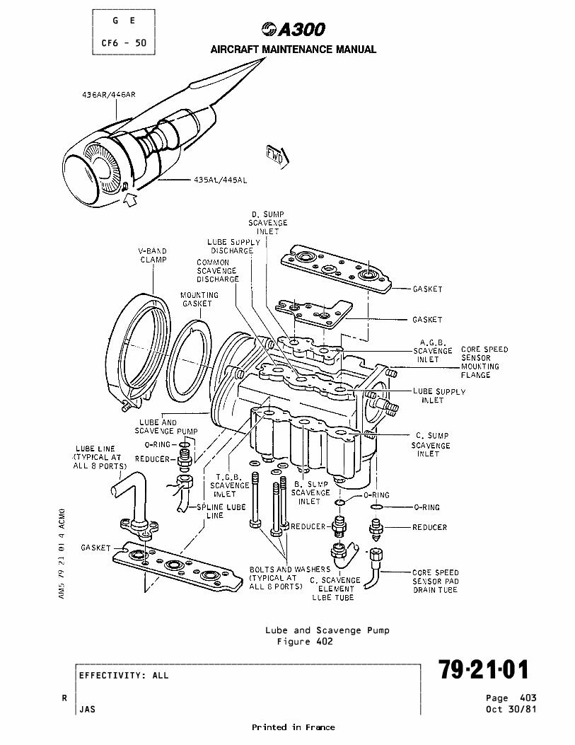
������������ � G E � � � � CF6 - 50 � ������������
Lube and Scavenge Pump Figure 402
�������������������������������������������������������������� �EFFECTIVITY: ALL ������������������������������������������������������������������� 79-21-01 � � � �R Page 403 � � JAS Oct 30/81

������������ � G E � � � � CF6 - 50 � ������������ (3.05 and 3.39 m.daN). Safety with 0.032 in. (0.813 mm) corrosion- resistant steel lockwire. (4)Place container under lube and scavenge pump. (5)Disconnect electrical connector from core speed sensor. (6)Remove lube supply inlet screen ; use screen to lift shut-off valve and drain supply line. (7)Remove the core speed (N2) sensor and brackets. (8)Disconnect all inlet and outlet lines by removing bolts and washers.R (9)Remove spline lube line and reducer. Discard 0-ring.R (10)Remove TCT sump scavenge element lube tube and reducers if applicable, discard 0-rings.R (11)Remove the V-band clamp bolt, spread clamp and separate pump from gear- box flange. Discard mounting gasket. WARNING : LUBE AND SCAVENGE PUMP WEIGHS APPROXIMATELY 18 LBS _______ (8.17KG). MAKE CERTAIN PUMP IS ADEQUATELY SUPPORTED BEFORE REMOVING FROM ENGINE. CAUTION : SUPPORT PUMP DURING CLAMP REMOVAL TO AVOID DAMAGE TO SHAFT _______ AND SPLINES. (12)Install protective covers on all open ports.
C. Installation (Ref. Fig.401 and 402) WARNING : MAKE CERTAIN CIRCUIT BREAKERS ARE OPEN, SAFETIED AND TAGGED _______ BEFORE ATTEMPTING MAINTENANCE PROCEDURES. INADVERTEND ENGINE START OR THRUST REVERSER OPERATION COULD RESULT IN DEATH OR SERIOUS INJURY TO PERSONNEL. (1)Spread V-band clamp and slip over gearbox mounting flange. (2)Lubricate mounting gasket with engine oil and place on pump flange.R Hang gasket outward over locating dowel pin at 12 oLclock on pump flange. Lubricate pump splines and gearbox splines with engine oil. (3)Align pump drive splines and slide pump aft into mounted position.R Make sure that pump locating dowel pin enters hole in gearbox flange. (4)Position V-band clamp over pump and gearbox flanges with bolt head fa- cing down and located at 8LoLclock position (viewed from forward looking aft). (5)Tap rim of clamp with plastic mallet to seat clamp properly and distri-R bute tension while tightening bolt. Tighten to 70-90 lfb-in (0.79-1.01R m.daN) and safety with 0.032 in. (0.013 mm) dia corrosion - resistant steel lockwire. WARNING : LUBE AND SCAVENGE PUMP WEIGHS APPROXIMATELY 18 LBS (8.17 KG). _______ MAKE CERTAIN PUMP IS ADEQUATELY SUPPORTED WHEN INSTALLING ON ENGINE. CAUTION : DO NOT PERMIT WEIGHT OF LUBE AND SCAVENGE PUMP TO REST ON _______ DRIVE SHAFT SPLINES DURING INSTALLATION OR DAMAGE TO SPLINES COULD RESULT. (6)Connect all inlet and outlet lines as follows : (a)Lubricate gaskets with engine oil and install gaskets on pump.R (b)Connect 8 lines with bolts and washers ; tighten to torque of 55-70 lbf -in (0.62-0.79 m.daN). NOTE : All bolts are identical. Start and initially tighten all bolts ____ fingertight to avoid cross threading. (7)Connect spline lube line as follows :
�������������������������������������������������������������� �EFFECTIVITY: ALL ������������������������������������������������������������������� 79-21-01 � � � � Page 404 � � JAS Oct 30/81

������������ � G E � � � � CF6 - 50 � ������������ (a)Lubricate new O-ring with engine oil, and install on spline lube line reducer. (b)Install reducer and tighten to torque of 135-150 LBF-in (11.2.12.5 lbf-ft.). (1.53-1,70m.daN). (c)Connect spline lube line ; tighten to torque of 135-150 lbf-in. (11.2- 12.5 lbf.ft.) (1.53-1.70 n.daN). (d)Safety reducer and spline lube line with 0.032 in. (0.813) dia. (8)Connect TCT sump scavenge element lube tube as follows : (a)Lubricate 2 new O-rings with engine oil, and install on reducers. (b)Install reducer in filter pressure outlet port ; tighten to torque of 135-150 lbf-in. (11.2-12.5 lbf.ft) (1.53-1.70 m.daN). (c)Install reducer in TCT sump scavenge element magnetic chip detector port ; tighten to torque of 155.175 lbf.in. (13.14.6 lbf.ft) (1.75- -1.97 m.daN) (d)Connect tube to the two reducers installed above ; tighten the B-nuts to torque of 270-300 lbf.in. (22.5-25 lbf.ft.) (3.05-3.39 m.daN). CAUTION : TO PREVENT OVER-TORQUING OF REDUCERS, RESTRAIN WHILE _______ TIGHTENING B-NUTS. (e)Assemble clamp to bracket and TCT sump scavenge element lube and tighten bolt to torque of 24-27 lbf.in. (0.27-0.30 m.daN). (9)Install core speed sensor as follows : (a)Position key in slot in lube pump forward shaft. (b)Assemble sensor rotor on shaft. Make sure that key is fully engaged with both rotor and shaft. (c)Install nut and washer on shaft ; tighten to torque of 100-120 lbf.in. (8.33-10 lbf.ft) (1.13-1.35 m.daN). (d)Position gasket and sensor casing on pump (electrical connection at 12LoLclock), install brackets, washers and nuts ; tighten to torque of 55-70 lbf.in. (0.62-0.79m.daN). (e)Connect electrical connector to core speed sensor. Safety connector with 0.020 in. (0.508 mm) dia. corrosion-resistant steel lockwire. CAUTION : TO RPEVENT DAMAGE TO ELECTRICAL CONNECTOR, DO NOT USE ANY _______ TOOL OTHER THAN PLUG PLIERS TO DISCONNECTO OR CONNECT PLUG. WHEN CONNECTING PLUG, DO NOT OVERTIGHTEN.R (10)Fill oil tank with engine oil.R
D. Test (1)Make certain that working area is clean and clear of tools and miscella- neous items of equipment. (2)Close fan cowls (Ref. 71-13-00, P. Block 301). (3)Remove safety clips and tags and close circuit breakers : 1EP, 2EP, 1JH, 2JH, 2KG, 1JM and 2KM. (4)Dry motor engine for 3 to 5 minutes to purge lube system of air and check for leaks. (5)Check oil level after coastdown, then refill to 4 quarts (3.8 liters) low if necessary. (6)Operate engine at Ground Idle or above for a minimum of 3 minutes. NOTE : This step may be performed during aircraft or engine ground ____ checks. (7)Check pump for proper operation, and pump and tubing for oil leakage
�������������������������������������������������������������� �EFFECTIVITY: ALL ������������������������������������������������������������������� 79-21-01 � � � � Page 405 � � JAS Oct 01/91

������������ � G E � � � � CF6 - 50 � ������������ at next engine run. NOTE : Maximum allowable seal drain leakage is 0.25 cc (0.015 in³) ____ per minute.R (8)Perform test as indicated in TType of testing after engine componentR replacementT (Ref. 71-00-00, P. Block 501).R (9)Fill tank to full mark.
�������������������������������������������������������������� �EFFECTIVITY: ALL ������������������������������������������������������������������� 79-21-01 � � � � Page 406 � � JAS Oct 01/92

������������ � G E � � � � CF6 - 50 � ������������ SCAVENGE OIL FILTER - SERVICING _______________________________
NOTE : Servicing procedures are identical for LH and RH scavenge oil filters. ____
1. Reason for the Job __________________R To remove, inspect, clean (if applicable), and install the filter elementR into the filter assembly.
2. Equipment and Materials _______________________ NOTE : Equivalent substitutes may be used instead of the following items. ____ ------------------------------------------------------------------------------- ITEM DESIGNATION ------------------------------------------------------------------------------- A. Material No.03-002 Oils (Ref. 20-31-00) B. Material C04-004 Cleaning Compounds and Solvents (Ref. 20-32-00) C. Material C04-002 Cleaning Compounds and Solvents (Ref. 20-32-00) D. Strap Wrench E. Container (Capacity : 30 liters approx. 8 US Gallons, 32 US Quarts) F. Circuit Breaker Safety Clips G. Corrosion-Resistant Steel Lockwire, Dia 0.032 in. (0.813 mm) H. Dry Filtered Air Referenced Procedures - 71-13-00, P. Block 301 Cowl Doors - 71-00-00, P. Block 501 Power Plant - 12-13-79, P. Block 1 Replenishing - Engines
�������������������������������������������������������������� �EFFECTIVITY: ALL ������������������������������������������������������������������� 79-22-01 � � � � Page 301 � � JAS Oct 01/93

������������ � G E � � � � CF6 - 50 � ������������ 3. Procedure _________
A. Job Set-up (1)Open, safety and tag the following circuit breakers for the appropriate engine and open engine cowls (Ref. 71-13-00, P. Block 301).
B. Filter Element Removal/Installation (Ref. Fig. 301 ) (1)Removal (a)Place container under scavenge oil filter. (b)Cut and remove lockwire then remove filter bowl using a strap wrench. NOTE : A filter service shut off valve prevents oil loss when filter ____ bowl is removed. (c)Remove and discard pre-formed packing from filter head. (d)Remove filter element from filter bowl.R (e)Remove and discard pre-formed packings if the element is reusable.
R C. Inspection before Cleaning or DiscardingR (1)Inspection (a)Visually inspect filter, record the degree and nature of excessive residue. NOTE : Any unusual or excessive residue should be investigated and ____ corrective action taken before further engine operation.
R D. Cleaning of Reusable Filter Element (1)Ultrasonic Cleaning (Preferred Method) WARNING : PERFORM THIS OPERATION IN AN APPROVED CLEANING CABINET OR _______ WELL VENTILATED AREA. TAKE PRECAUTIONS TO MINIMIZE FIRE HAZARDS AND PREVENT INHALATION OF VAPORS. REPEATED OR PROLONGED CONTACT OF SOME CLEANING MATERIALS WITH THE SKIN WILL REMOVE SKIN OILS AND MAY CAUSE SEVERE DERMATITIS. NOTE : Filter must be checked for excessive residue prior to cleaning. ____ (a)Disassemble filter by removing hex head bolt, element adapter assembly and filter element wafers from element closure assembly. (b)Ultrasonically clean the filter packs for 10 to 20 minutes using solvent C04-004. Suspend element vertically to permit loosened dirt to fall out. Operate at 40KC (Kilocycle) with 30 watts output for square foot of active wall. (c)Brush both sides of all wafers with a stiff brush while immersed in solvent C04-002. NOTE : Do not use a wire brush. ____ (d)Ultrasonically clean filter elements for 3 to 5 minutes using solvent C04-002. Suspend elements vertically. (e)Rinse filter in running warm water. (f)Oven dry filter at 200•F (93•C) or less, or air dry in clean protected area. CAUTION : DO NOT USE CONVENTIONAL SHOP AIR. IT USUALLY CONTAINS DIRT, _______ WATER AND OIL. (g)Examine wafers using 10-power glass and strong light. If contaminants are still present, repeat cleaning process. (h)Assemble filter element by stacking up wafers on element closure assembly, installing closure assembly and securing with hex head
�������������������������������������������������������������� �EFFECTIVITY: ALL ������������������������������������������������������������������� 79-22-01 � � � � Page 302 � � JAS Oct 01/93

������������ � G E � � � � CF6 - 50 � ������������
Scavenge Oil Filter - Reusable TypicalR Figure 301
�������������������������������������������������������������� �EFFECTIVITY: ALL ������������������������������������������������������������������� 79-22-01 � � � � Page 303 � � JAS Oct 01/93

������������ � G E � � � � CF6 - 50 � ������������ bolt. TORQUE bolt to between 55 and 65 lbf. in. (0.62 and 0.73 m.daN). CAUTION : TWO TYPES OF FILTER ELEMENTS EXIST. TYPE 1 HAS 50 WAFERS _______ AND TYPE II HAS 46 WAFERS. DO NOT INTERMIX FILTER PARTS. NOTE : Minimum of 5 lbf. in. (0.05 m.daN) running torque must exist ____ on closure bolt.R WARNING : PERFORM THIS OPERATION IN AN APPROVED CLEANING CABINET OR _______ WELL VENTILATED AREA. TAKE PRECAUTIONS TO MINIMIZE FIRE HAZARDS AND PREVENT INHALATION OF VAPORS. REPEATED OR PRO- LONGED CONTACT OF SOME CLEANING MATERIALS WITH THE SKIN WILL REMOVE SKIN OILS AND MAY CAUSE SEVERE DERMATITIS. (2)Immersion cleaning (alternate method) (a)Disassemble filter by removing hex head bolt, element adapter assembly and filter element wafers from element closure assembly.R CAUTION : DO NOT USE WIRE BRUSH. _______ (b)Immerse filter wafers in solvent C04-002 and clean using a stiff brush. (c)Back-flush each wafer with solvent.R CAUTION : DO NOT USE CONVENTIONAL SHOP AIR. IT CONTAINS DIRT, _______ WATER AND OIL. (d)Back-flush each wafer with clean, filtered compressed air. (e)Examine wafers using 10-power glass and strong light. If contaminants are still present, repeat cleaning process.R CAUTION : TWO TYPES OF FILTER ELEMENTS EXIST. TYPE I HAS 50 WAFERS, _______ TYPE II HAS 46 WAFERS. DO NOT INTERMIX FILTER PARTS. (f)Assemble filter element by stacking up wafers on element closure assembly, installing closure assembly and securing with hex head bolt. TORQUE bolt to between 55 and 65 lbf. in. (0.62 anf 0.73 m.daN). NOTE : Minimum of 5 lbf. in. (0.05 m.daN) of running torque must ____ exist on closure bolt. (3)Inspection after cleaning (a)Check filter wafers for dents, holes or scuffs. If mesh opening appears to have been deformed to 3 times the normal comparative opening dimensions, replace wafer.
R E. Installation of Filter ElementR (1)InstallationR (a)Place cleaned or new filter element in bowl. If reusable type, installR a preformed packing at both ends of element. NOTE : Element filter (only) may be installed with either end down. ____R (b)Lubricate new preformed packing, sealing surfaces and thread of filter head and bowl with engine lubricating oil.R CAUTION : MAKE SURE THAT PACKING IS PROPERLY INSTALLED IN GROOVE _______ TO AVOID DAMAGE DURING BOWL INSTALLATION.R (c)Install new preformed packing in groove on bowl. (d)Turn bowl by hand or with strap wrench until bowl bottoms against filter head. Safety bowl with 0.032 in. (0.813 mm) dia. corrosion- resistant steel lockwire. NOTE : Bowl must bottom against head to ensure proper O-ring seating. ____
�������������������������������������������������������������� �EFFECTIVITY: ALL ������������������������������������������������������������������� 79-22-01 � � � � Page 304 � � JAS Oct 01/93
������������ � G E � � � � CF6 - 50 � ������������R E. Close-up and Tests (1)Remove tools, equipment, loose hardware, spilled fluid and debris from maintenance area. (2)Close fan cowl (Ref. 71-13-00, P. Block 301). (3)Remove safety clips and tags, and close circuit breakers 1JH, 2JH, 2KG, 1KM and 2KM. (4)Check oil level in oil tank. Add oil if required (Ref. 12-13-79). (5)Carry out an idle check (Ref. 71-00-00, P. Block 501) for 3 to 5 minutes to purge oil system of air, and check scavenge oil filter for leakage. (6)Check oil level after coastdown, and service oil tank if required, with engine oil Material No.03-002.
�������������������������������������������������������������� �EFFECTIVITY: ALL ������������������������������������������������������������������� 79-22-01 � � � � Page 305 � � JAS Oct 01/93

������������ � G E � � � � CF6 - 50 � ������������ SCAVENGE OIL FILTER - REMOVAL/INSTALLATION __________________________________________
NOTE : This procedure deals with removal/installation of filter ____ assembly. Removal/installation of filter element is covered in 79-22-01, P. Block 301).
1. Equipment and Materials _______________________ NOTE : Equivalent substitutes may be used instead of the following items. ____ ------------------------------------------------------------------------------- ITEM DESIGNATION ------------------------------------------------------------------------------- A. Material C02-019 Anti-Seize Compounds, Lubricants Oils (Ref. 20-32-00) Referenced Procedures - 71-13-00, P. Block 301 Cowl Doors - 71-00-00, P. Block 501 Power Plant - 12-13-79, P. Block 1 Replenishing - Engines
2. Procedure _________
A. Job Set-Up (1)Open, safety and tag the following circuit breakers for the appropriate engine and open engine cowls (Ref. 71-13-00, P. Block 301).
(2)Open fan cowl 435AL on LH engine and 445AL on RH engine (Ref. 71-13-00, P. Block 301). WARNING : EACH FAN COWL WEIGHS APPROXIMATELY 156 LBS (71KG). MAKE _______ CERTAIN SUFFICIENT PERSONNEL ARE AVAILABLE TO ASSIST IN OPENING OF THE COWLS.
B. Removal (Ref. Fig. 401 ) (1)Disconnect inlet and outlet tubes.R (2)Disconnect tubes from inlet and outlet ports (Ref. Fig. 401 ) Detail B.R (3)Remove nuts ; lower filter assembly from mounting bracket.
C. Installation (Ref. Fig. 401 ) (1)Position filter assembly on mounting breaket with IN port facing aft ; secure with washers and nuts. TORQUE to between 55 and 70 lbf.in. (0.62 - 0.79 m.daN). NOTE : If fire sensing element bracket is to be installed on inlet tube, ____ use 2 bolts without washers where the bracket is installed. Use a bolt and washer at the other two bolts holes. (2)Install gaskets and connect inlet and outlet tubes ; TORQUE to between 55 and 70 lbf.in. (0.62 - 0.79 m.daN) and wirelock.R (3)Connect tubes to inlet and outlet ports : TORQUE to between 130 andR 150 lbf.in. (1.47 and 1.70 m.daN).R (4)Motor engine to check for leakageR (5)Operate engine and check for leakage.R (6)Service oil tank with oil C02-019.R (7)Make certain that working area is clean and clear of tools and miscella- neous items of equipment.
�������������������������������������������������������������� �EFFECTIVITY: ALL ������������������������������������������������������������������� 79-22-01 � � � � Page 401 � � JAS Apr 01/89

������������ � G E � � � � CF6 - 50 � ������������
Scavenge Oil FilterR Figure 401
�������������������������������������������������������������� �EFFECTIVITY: ALL ������������������������������������������������������������������� 79-22-01 � � � � Page 402 � � JAS Apr 01/89

������������ � G E � � � � CF6 - 50 � ������������R (8)Close fan cowls (Ref. 71-13-00, P. Block 301).R (9)Remove safety clips and tags, and close circuit breakers 2KG, 1JH, 2JH, 1KM and 2KM.
�������������������������������������������������������������� �EFFECTIVITY: ALL ������������������������������������������������������������������� 79-22-01 � � � � Page 403 � � JAS Apr 01/89
������������ � G E � � � � CF6 - 50 � ������������ FUEL/OIL HEAT EXCHANGER - REMOVAL/INSTALLATION ______________________________________________
NOTE : Some engines may include an eductor and valve assembly fitted to the ____ fuel/oil heat exchanger. Removal/Installation procedures are identical for fuel/oil heat exchan- ger fitted with an eductor and valve assy or not.
CAUTION : BEFORE ATTEMPTING REMOVAL/INSTALLATION PROCEDURES FOR FUEL/OIL HEAT _______ EXCHANGER, MAKE CERTAIN FIRE EXTINGUISHING EQUIPMENT IS AVAILABLE IN PROXIMITY TO WORK AREA.
1. Equipment and Materials _______________________ NOTE : Equivalent substitutes may be used instead of the following items. ____ ------------------------------------------------------------------------------- ITEM DESIGNATION ------------------------------------------------------------------------------- A. Material 03-002 Oils (Ref. 20-31-00) B. Electrical Ground Power Unit, 3-Phase, 115/200 V, 400 Hz, 90 KVA C. Container (Capacity 30 liters, 8 US Gallons, 32 US Quarts) D. Circuit Breaker Safety Clips E. Corrosion-Resistant Steel Lockwire, Dia 0.032 in (0.813 mm) Referenced Procedures - 24-41-00, P. Block 301 External Power - 71-13-00, P. Block 301 Cowl Doors - 28-21-12, P. Block 401 Booster Pump - 71-00-00, P. Block 501 Power Plant General - 12-13-79, P. Block 1 Replenishing - Engines
2. Procedure _________
A. Job Set-Up (1)Open, safety and tag the following circuit breakers : ------------------------------------------------------------------------------ PANEL SERVICE IDENT. LOCATION ------------------------------------------------------------------------------ 123VU ENGINES/IGNITION/SYS A 1JH 301/D16 123VU ENGINES/IGNITION/SYS B 2JH 301/D17 123VU ENGINES/START/CONTRL 2KG 301/D14 123VU ENG 1/REV/CONTRL 1KM 302/C 2 123VU ENG 2/REV/CONTRL 2KM 302/C15 123VU FIRE EXTING/ENG 1/SQUIB/1B 1WE 302/C 7 123VU FIRE EXTING/ENG 2/SQUIB/1B 2WE 302/C10 123VU FIRE EXTING/ENG 1/SQUIB/2B 3WE 302/C 8 123VU FIRE EXTING/ENG 2/SQUIB/2B 4WE 302/C11 22VU ENG 1/FIRE EXTING SQUIB/1A 5WE 204/K 3 22VU ENG 2/FIRE EXTING SQUIB/1A 6WE 204/K 7 22VU ENG 1/FIRE EXTING SQUIB/2A 7WE 204/K 4 22VU ENG 2/FIRE EXTING SQUIB/2A 8WE 204/K 6
�������������������������������������������������������������� �EFFECTIVITY: ALL ������������������������������������������������������������������� 79-22-02 � � � �R Page 401 � � JAS Jan 01/88
������������ � G E � � � � CF6 - 50 � ������������ (2)At panel 46VU (a)Unsafety fire control handles.R (b)Move fire control handles upwards (LP fuel fire shut-off valves clo- sed) and display a warning notice to prohibit their use. CAUTION : IN THIS POSITION (LP FUEL FIRE SHUT OFF VALVE CLOSED), DO _______ NOT MOVE FIRE CONTROL HANDLES SIDEWAYS OR INADVERTENT OPE-R RATION OF FIRE EXTINGUISHER BOTTLES COULD OCCUR. (3)Open fan cowls 435AL, 436AR on LH engine or 445AL, 446AR on RH engineR (Ref. 71-13-00, P. Block 301). WARNING : EACH FAN COWL WEIGHS APPROXIMATELY 156 LBS (71KG). MAKE _______ CERTAIN SUFFICIENT PERSONNEL ARE AVAILABLE TO ASSIST IN OPENING OF THE COWLS.
B. Removal (Ref. Fig.401 and 402) NOTE : Disregard steps pertaining to eductor and valve assembly if not ____ applicable. (1)Place container under oil tank. (2)Cut and remove lockwire, then remove drain plug and drain oil from tank. Discard O-ring. WARNING : A MINIMUM OF 5 MINUTES SHOULD ELAPSE AFTER ENGINE SHUTDOWN _______ BEFORE REMOVING ANY COMPONENT IN OIL SYSTEM TO ALLOW TANK PRESSURE TO BLEED OFF. HOT OIL GUSHING FROM TANK COULD CAUSE SEVERE BURNS. (3) Place suitable container under fuel/oil heat exchanger. (4) Disconnect signal tube (2) from eductor and valve. (5) Disconnect eductor pressure tube (1) from the top of the valve. (6)Disconnect eductor discharge tube (10) from valve. (7)Disconnect drain can discharge tube (9) from valve. (8)Disconnect clamp (8) and signal tube from eductor and valve bracket. (9)Remove oil inlet tube (7). Retain gasket (6) for installation. (10)Remove oil outlet tube (4). Retain gasket (5) for installation. (11)Remove heat exchanger, eductor and valve and bracket. Retain gasket (3) for installation. NOTE : Heat exchanger gasket are re-usable and should be retained with ____ fuel pump and attaching hardware. (12)Install protective caps and protective covers to all flange surfaces. NOTE : Oil wetting of internal surfaces is an important safeguard against ____ atmospheric corrosion damage. Flange sealing surfaces must be protected from handling damage. Surface finishes are critical to sealing requirements.R (13)Wrap and box-up unit to protect against handling damage.
C. Preparation of Replacement Component (1)Clean work area and dry with lint-free cloth. (2)Visually check gaskets, eductor and valve bracket, and unions for con- dition. Check tubes for cracks, distortion, corrosion, etc... (3)Remove blanking plugs from the ports of new heat exchanger, then install them on the ports of the heat exchanger removed.
D. Installation WARNING : MAKE CERTAIN CIRCUIT BREAKERS ARE OPEN, SAFETIED AND TAGGED BEFO- _______
�������������������������������������������������������������� �EFFECTIVITY: ALL ������������������������������������������������������������������� 79-22-02 � � � � Page 402 � � JAS Jan 30/82
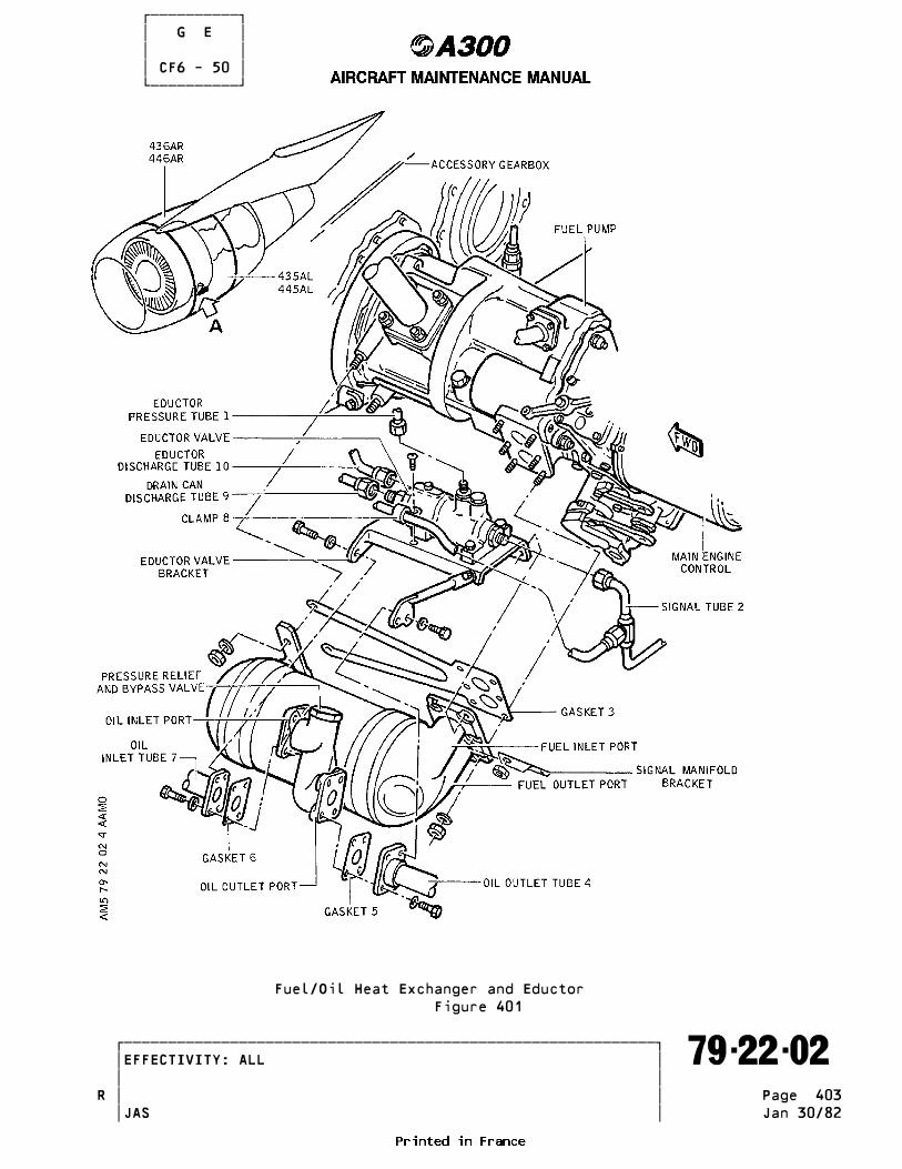
������������ � G E � � � � CF6 - 50 � ������������
Fuel/Oil Heat Exchanger and Eductor Figure 401
�������������������������������������������������������������� �EFFECTIVITY: ALL ������������������������������������������������������������������� 79-22-02 � � � �R Page 403 � � JAS Jan 30/82
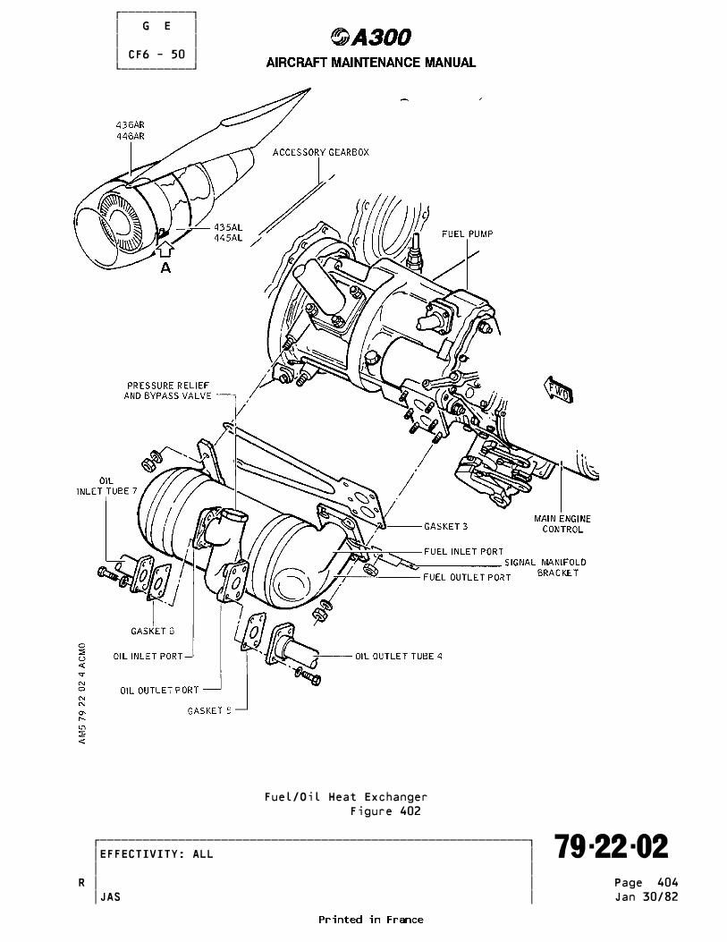
������������ � G E � � � � CF6 - 50 � ������������
Fuel/Oil Heat Exchanger Figure 402
�������������������������������������������������������������� �EFFECTIVITY: ALL ������������������������������������������������������������������� 79-22-02 � � � �R Page 404 � � JAS Jan 30/82

������������ � G E � � � � CF6 - 50 � ������������ FORE ATTEMPTING MAINTENANCE PROCEDURES. INADVERTENT ENGINE START OR THRUST REVERSER OPERATION COULD RESULT IN DEATH OR SERIOUS INJURY TO PERSONNEL.
CAUTION : NO CRACKS, NO DENTS, NO BULGING ALLOWED ON FUEL/OIL HEAT _______ EXCHANGER. (1)Position gasket (3) on fuel pump and install heat exchanger. TORQUE nutsR to between 100 and 130 lbf.in. (1.13 and 1.46 m.daN) (8.33 to 10.83 lbf.ft.). NOTE : Start with nut on forward middle stud before fully seating heat ____ exchanger. Omit nut on upper aft stud for installation of eductor and valve bracket. (2)Lightly lubricate gaskets (5) and (6) with engine oil. Position gaskets on oil inlet and outlet tube flange of fuel/oil heat exchanger. (3)Align eductor and valve bracket with upper bolt holes of oil outlet tube (4) and upper inboard hole of oil inlet tube (7), and install valve andR bracket and flanges. TORQUE bolts to between 55 and 70 lbf.in. (0.62 to 0.79 m.daN).R (4)Connect eductor discharge tube (10) to valve. TORQUE nut to between 270R and 300 lbf.in. (22.5-25 lbf.ft.) (3.05 and 3.39 m.daN). Safety nut with 0.032 in. (0.813 mm) Dia. corrosion-resistant steel lockwire.R (5)Connect eductor pressure tube (1) to valve. TORQUE nut to between 180R and 200 lbf.in. (15-16.7 lbf.ft.) (2.03 and 2.26 m.daN). Safety tube with 0.032 in. (0.813 mm) Dia. corrosion-resistant steel lockwire.R (6)Connect drain can discharge tube (9) to valve. TORQUE nut to between 270R and 300 lbf.in. (3.05 and 3.39 m.daN) (22.5 and 25 lbf.ft.).R (7)Connect signal tube (2) to valve. TORQUE nut to between 135 and 150R lbf.in. (11.3 and 12.5 lbf.ft.) (1.53 and 1.70 m.daN). Safety nut with 0.032 in. (0.813 mm) Dia. corrosion resistant steel lockwire. (8)Install clamp (8) attaching signal tube to eductor and valve bracket. (9)Lightly lubricate new O-ring with engine oil, install O-ring on drainR plug and install plug in oil tank. TORQUE drain plug to between 270 andR 300 lbf.in. (22.5 and 25 lbf.ft.) (3.05 and 3.39 m.daN) and safety with 0.032 in. (0.813 mm) Dia. corrosion-resistant steel lockwire. (10)Fill oil tank with engine oil (Ref. Paragraph 2.A). (11)Bleed oil system and check for leaks as follows : (a)Remove lube supply inlet screen from lube and scavenge pump. NOTE : A screen shut off valve prevents oil loss when screen is ____ removed. (b)Place suitable container of approximately 2 US Gallons (1.67 Imp gal. or 7.6 l) capacity under screen. Unseat screen shut off valve by holding screen partially in, and allow valve to bleed until steady stream of oil flows, indicating that supply inlet tube is purged of air.R (c)Install screen. TORQUE screen to between 55 and 70 lbf.in. (0.62 andR 0.79 m.daN) and safety with 0.032 in. (0.813 mm) dia. corrosion- resistant steel lockwire. CAUTION : EXERCISE CARE WHEN INSTALLING SCREEN IN LUBE AND SCAVENGE _______ PUMP. IMPROPER POSITIONING COULD RESULT IN DAMAGE TO SCREEN.
�������������������������������������������������������������� �EFFECTIVITY: ALL ������������������������������������������������������������������� 79-22-02 � � � � Page 405 � � JAS Jan 30/82
������������ � G E � � � � CF6 - 50 � ������������ E. Tests and Close-Up (1)Remove warning notice prohibiting the use of fire control handles. (2)Move fire control handles downwards (LP fuel fire shut-off valves open). (3)Connect electrical ground power unit and energize the aircraft elec- trical network (Ref. 24-41-00, P. Block 301). (4)Start fuel pumps (Ref. 28-21-00, P. Block 1). (5)Check the assembly for leakage. (6)Shut-off supply to fuel pumps. (7)De-energize aircraft electrical network and disconnect electrical ground power unit. (8)Remove safety clips and tags, and close the following circuit breakers : 1JH, 2JH, 2KG, 1KM, 2KM, 1WE, 2WE, 3WE, 4WE and 5WE (9)Dry motor engine (Ref. 71-00-00, P. Block 501) for 3 to 5 minutes to purge oil system of air, and check for leakage.R (10)Perform test as indicated in TType of testing after engine componentR replacementT (Ref. 71-00-00, P. Block 501).R (11)Check oil level after coastdown, and service oil tank if required (Ref. 12-13-79, P. Block 1).R (12)Remove tools, equipment, loose hardware, spilled fluids and debris from maintenance area.R (13)Close fan cowls (Ref. 71-13-00, P. Block 301).
�������������������������������������������������������������� �EFFECTIVITY: ALL ������������������������������������������������������������������� 79-22-02 � � � � Page 406 � � JAS Oct 01/92

������������ � G E � � � � CF6 - 50 � ������������R MAGNETIC PLUG - SERVICING _________________________
R 1. General _______R This procedure pertains to the servicing of the magnetic chip detector. TheR chip detector is an TassemblyT consisting of a magnetic probe and housing. ItR is located in the scavenge return line between the lube/scavenge pump and theR scavenge oil filter.
R 2. Equipment and Materials _______________________R -------------------------------------------------------------------------------R ITEM DESIGNATIONR -------------------------------------------------------------------------------R A. Material No.C02-019 Anti-seize Compounds, Lubricants, OilsR (Ref. 20-32-00)R B. Material No.C04-004 Cleaning Compounds and SolventsR (Ref. 20-32-00)R C. Container Suitable for OilR D. Corrosion-Resistant Steel LockwireR E. Torque Wrench 40-100 lbf. in.R (0.45 - 1.13 m.daN)R Referenced ProceduresR - 71-13-00, P. Block 301 Cowl DoorsR - 71-00-00, P. Block 501 Power PlantR - 12-13-79, P. Block 1 Servicing - Engines
R 3. Procedure _________
R A. Job Set-UpR (1)Open, safety and tag the circuit breakers for the appropriate engine andR open fan cowl doors (Ref. 71-13-00, P. Block 301).
R B. Removal of magnetic probeR (1)Configuration 01 (Ref. Fig. 301 )R CAUTION : THE MAGNETIC PROBE IS LOCKED IN THE HOUSING BY BAYONET PINS AND _______R SLOT ARRANGEMENT. THE PROBE MUST BE PUSHED IN BEFORE TURNING.R REPLACE ENTIRE MAGNETIC CHIP DETECTOR ASSEMBLY IF PROBE CANNOTR BE REMOVED BY HAND. DO NOT USE TOOLS TO REMOVE PROBE.R (a)Place a container under the magnetic chip detector to catch residualR oil.R (b)Push in on knob, turn it counterclockwise, and pull magnetic probe fromR housing.R NOTE : Normal resistance will be felt from O-ring friction. A self- ____R closing valve prevents oil loss when probe is removed under sta-R tic conditions.R (c)Remove O-ring(s) from magnetic probe and discard.R (d)Inspect magnetic probe per paragraph 3.F.(1).R (2)Configuration 02. (Ref. Fig. 302 )R CAUTION : THE MAGNETIC PROBE IS LOCKED IN THE HOUSING BY BAYONET PINS _______R AND SLOT ARRANGEMENT. THE PROBE MUST BE PUSHED IN BEFORER TURNING.R REPLACE ENTIRE MAGNETIC CHIP DETECTOR ASSEMBLY IF PROBE CANNOT
�������������������������������������������������������������� �EFFECTIVITY: ALL ������������������������������������������������������������������� 79-22-03 � � � � Page 301 � � JAS Jul 01/85

������������ � G E � � � � CF6 - 50 � ������������
Magnetic Chip Detector (Config 01)R Figure 301
�������������������������������������������������������������� �EFFECTIVITY: ALL ������������������������������������������������������������������� 79-22-03 � � � � Page 302 � � JAS Jul 01/85

������������ � G E � � � � CF6 - 50 � ������������ BE REMOVED BY HAND. DO NOT USE TOOLS TO REMOVE PROBE. (a)Place a container under the magnetic chip detector to catch residual oil.
(b)Push in on knob, turn it counterclockwise, and pull magnetic probe from housing. NOTE : Normal resistance will be felt from preformed packing friction. ____ A self-closing valve prevents oil loss when probe is removed un- der static conditions. (c)Remove preformed packing from magnetic probe and discard. (e)Inspect magnetic probe per paragraph 3.F.(1). (3)Configuration 03. (Ref. Fig. 303 ) (a)Place a container under the magnetic chip detector to catch residual oil. (b)Cut and remove lockwire from the magnetic probe. (c)Unscrew magnetic probe from housing. NOTE : Normal resistance will be felt from preformed packing friction. ____ A self-closing valve prevents oil loss when probe is removed un- der static conditions. (d)Remove preformed packing from magnetic probe and discard. (e)Inspect magnetic probe per paragraph 3.F.(1).R (4)Configuration 04. (Ref. Fig. 304 )R CAUTION : THE MAGNETIC PROBE IS LOCKED IN THE HOUSING BY BAYONET PINS _______R AND SLOT ARRANGEMENT. THE PROBE MUST BE PUSHED IN BEFORER TURNING.R REPLACE ENTIRE MAGNETIC CHIP DETECTOR ASSEMBLY IF PROBE CANNOTR BE REMOVED BY HAND. DO NOT USE TOOLS TO REMOVE PROBE.R (a)Place a container under the magnetic chip detector to catch residualR oil.R (b)Push in on knob, turn it counterclockwise, and pull magnetic probe fromR housing.R NOTE : Normal resistance will be felt from preformed packing friction. ____R A self-closing valve prevents oil loss when probe is removedR under static conditions.R (c)Remove preformed packing from magnetic probe and discard.R (d)Inspect magnetic probe per paragraph 3.F.(1)
C. Installation of the Magnetic Probe (1)Configuration 01. (Ref. Fig. 301 ) (a)Check magnetic probe for cleanliness. CAUTION : FAILURE TO INSTALL PREFORMED PACKING CAN RESULT IN EXCESSIVE _______ OIL LOSS DURING ENGINE OPERATION, WITH POSSIBLE ENGINE FAI- LURE. (b)Lubricate a new preformed packing with engine oil (C02-019) and install on the magnetic probe. Preformed packing shall occupy groove on shank closest to hex head of probe. (Ref. Fig. 301 ) NOTE : If new preformed packings are not available, the existing pre- ____ formed packings may be reused provided inspection confirms part serviceability. (c)Insert magnetic probe in housing by pushing and rotating clockwise to
�������������������������������������������������������������� �EFFECTIVITY: ALL ������������������������������������������������������������������� 79-22-03 � � � � Page 303 � � JAS Oct 01/89
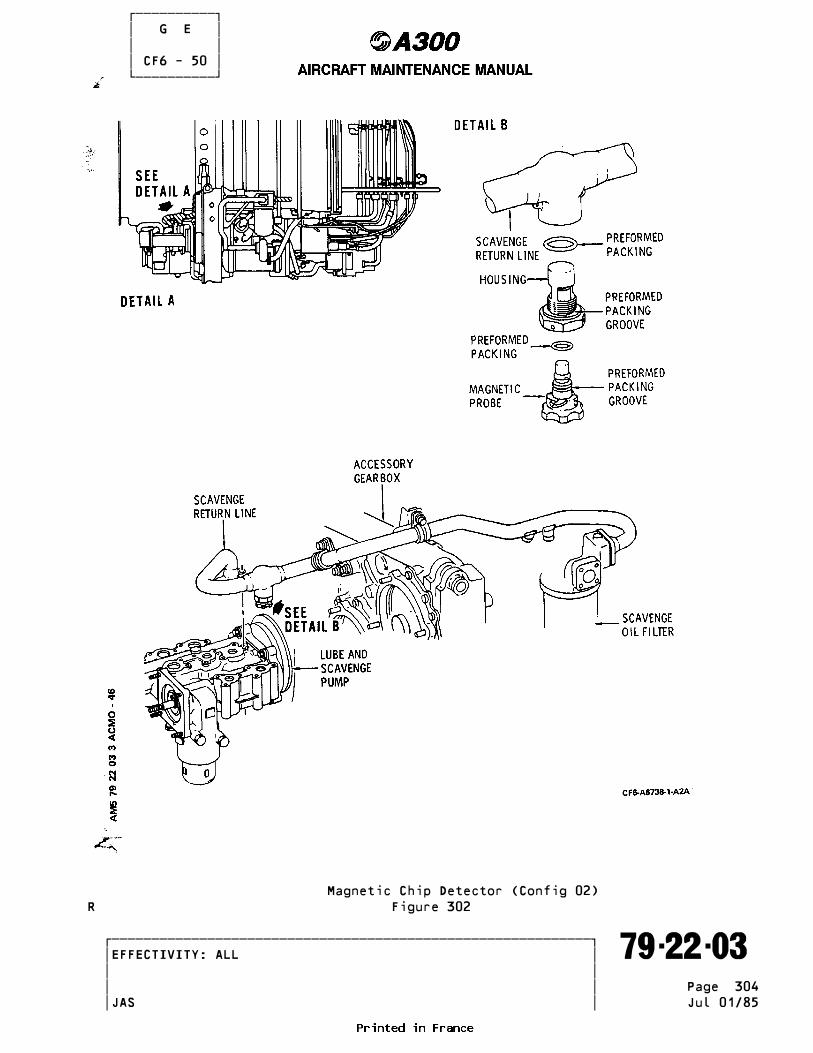
������������ � G E � � � � CF6 - 50 � ������������
Magnetic Chip Detector (Config 02)R Figure 302
�������������������������������������������������������������� �EFFECTIVITY: ALL ������������������������������������������������������������������� 79-22-03 � � � � Page 304 � � JAS Jul 01/85

������������ � G E � � � � CF6 - 50 � ������������
Magnetic Chip Detector (Config 03)R Figure 303
�������������������������������������������������������������� �EFFECTIVITY: ALL ������������������������������������������������������������������� 79-22-03 � � � � Page 305 � � JAS Jul 01/85

������������ � G E � � � � CF6 - 50 � ������������
Magnetic Chip Detector (Config 04)R Figure 304
�������������������������������������������������������������� �EFFECTIVITY: ALL ������������������������������������������������������������������� 79-22-03 � � � � Page 306 � � JAS Oct 01/89

������������ � G E � � � � CF6 - 50 � ������������ engage in slot detent and release. (d)Check for positive locking of probe by pulling downward on probe. (2)Configuration 02. (Ref. Fig. 302 ) (a)Check magnetic probe for cleanliness. CAUTION : FAILURE TO INSTALL PREFORMED PACKING CAN RESULT IN EXCESSIVE _______ OIL LOSS DURING ENGINE OPERATION, WITH POSSIBLE ENGINE FAI- LURE. (b)Lubricate a new preformed packing with engine oil (C02-019) and install on the magnetic probe. Preformed packing shall occupy groove on shank closest to scalloped head of probe. (Ref. Fig. 302 ) NOTE : If a new preformed packing is not available, the existing pre- ____ formed packing may be reused provided inspection confirms part serviceability. (c)Insert magnetic probe in housing by pushing and rotating clockwise to engage pins in slot detent and release. (d)Check for positive locking of probe by pulling downward on probe. (e)With the probe properly installed, slide spring clip retainer between probe handle and magnetic chip detector housing. Clip retainer lanyard to an available safetywire hole in the probe housing. (3)Configuration 03. (Ref. Fig. 303 ) (a)Check magnetic probe for cleanliness. CAUTION : FAILURE TO INSTALL PREFORMED PACKING CAN RESULT IN EXCESSIVE _______ OIL LOSS DURING ENGINE OPERATION, WITH POSSIBLE ENGINE FAI- LURE. (b)Lubricate a new preformed packing with engine oil (C02-019) and install on the magnetic probe. Preformed packing shall occupy groove on shank closest to hex head of probe. (Ref. Fig. 303 ) NOTE : If a new preformed packing is not available, the existing pre- ____ formed packing may be reused provided inspection confirms part serviceability. (c)Insert magnetic probe in housing by turning clockwise until handtight. After insuring proper engagement of packing seals, torque to between 40 and 50 lbf.in. (0.45 and 0.56 m.daN) and wirelock. (4)Configuration 04. (Ref. Fig. 304 ) (a)Check magnetic probe for cleanliness. CAUTION : FAILURE TO INSTALL PREFORMED PACKING CAN RESULT IN EXCESSIVE _______ OIL LOSS DURING ENGINE OPERATION, WITH POSSIBLE ENGINE FAILURE. (b)Lubricate a new preformed packing with engine oil (C02-019) and install on the magnetic probe. Preformed packing shall occupy the only groove on shank of probe (Ref. Fig. 304 ). NOTE : If a new preformed packing is not available, the existing ____ preformed packing may be reused provided inspection confirms part serviceability. (c)Insert magnetic probe in housing by pushing and rotating clockwise to engage pins, in slot detent and release. CAUTION : PROBE MUST BE A SNUG FIT WITHOUT SIDE PLAY. OTHER WISE CHECK _______ THAT PROBE IS THE CORRECT P/N FOR THAT HOUSING. PROBE MUST NEVER BE LOOSE FITTING IN HOUSING.
�������������������������������������������������������������� �EFFECTIVITY: ALL ������������������������������������������������������������������� 79-22-03 � � � �R Page 307 � � JAS Oct 01/89

������������ � G E � � � � CF6 - 50 � ������������ (d)Check for positive locking of probe by pulling downward on probe.
D. Removal of Magnetic Chip Detector NOTE : This procedure is to be used only when removing the entire magnetic ____ chip detector assembly. Refer to paragraph 3.B. of applicable confi- guration for removal of the magnetic probe only. (1)Place a container under the magnetic chip detector to catch residual oil. (2)Cut lockwire and remove magnetic chip detector (housing) from the sca- venge return line by turning it counterclockwise. (3)Discard preformed packing from housing. (4)Install protective plastic plug on the scavenge return line and place the magnetic chip detector in a protective container.
E. Installation of the Magnetic Chip Detector (Probe Body). NOTE : This procedure is to be used only when installing the entire magne- ____ tic chip detector assembly. Refer to paragraph 3.B. of application configuration for installation of the magnetic probe only. NOTE : If a previously used chip detector is being installed, ensure that ____ it is clean and has been inspected per paragraph 3.F. (1)Remove plastic plug from scavenge return line. (2)Lubricate new preformed packing with engine oil (C02-019) and install in groove on the housing for the correct configuration (Ref. Fig. 301, 302 and 303) (Ref. Fig. 304 ) CAUTION : FAILURE TO INSTALL PREFORMED PACKING CAN RESULT IN EXCESSIVE _______ OIL LOSS DURING ENGINE OPERATION, WITH POSSIBLE ENGINE FAILURE. (3)Install magnetic chip detector in oil scavenge manifold and screw in by turning clockwise. TORQUE to between 90 and 100 lbf.in. (1.02 and 1.13 m.daN) torque and wirelock. CAUTION : INSTALLATION OF MAGNETIC PROBE AND/OR HOUSING WITHOUT _______ PREFORMED PACKING CAN RESULT IN EXCESSIVE OIL LOSS DURING ENGINE OPERATION, WITH POSSIBLE ENGINE FAILURE. (4)Remove the magnetic probe per paragraph 3.B. of applicable configuration, and check for presence and serviceable condition of preformed packing on the probe. Re-install probe per paragraph 3.C. of applicable configura- tion. (5)Torque magnetic plug to a special torque value between 40 and 50 lbf.in. (0.45 and 0.56 m.daN) and lockwire to housing.
F. Inspection/Check (1)Remove magnetic probe from housing and check for : (a)Foreign particles and contaminants. (b)Replace O-ring(s). (c)Bent locking pins, configuration 01 only. (d)Proper probe insertion. Replace assembly if difficult to insert or fails to lock. (2)Remove housing and check for : (a)Replace O-ring. (b)Self-closing valve for freedom of movement and proper seating. Replace assembly if valve sticks or does not seat properly.
�������������������������������������������������������������� �EFFECTIVITY: ALL ������������������������������������������������������������������� 79-22-03 � � � �R Page 308 � � JAS Oct 01/89
������������ � G E � � � � CF6 - 50 � ������������ (c)Damaged or missing omni all models seal (Ref. Fig. 304 ), replace entire probe/housing assembly if seal is damaged or missing.
G. Cleaning (1)Separate magnetic probe from probe body ; clean by swirling in trichlo- roethylene (C04-004). WARNING : THIS SOLVENT IS TOXIC AND SHOULD BE USED WITH ADEQUATE VENTI- _______ LATION. AVOID PROLONGED BREATHING OF VAPORS. REPEATED OR PROLONGED CONTACT WITH THE SKIN WILL REMOVE SKIN OILS AND CAUSE SEVERE DERMATITIS.
H. Tests (1)Remove safety clips and tags, and close circuit breakers 1JH, 2JH, 2KG, 1KM and 2KM.R Pre SB GE 79-035 (2)Carry out an idle check for 3 to 5 minutes to purge oil system of air (Ref. 71-00-00, P. Block 501) and check for leakage.R End Pre SB GE 79-035R Post SB GE 79-035R (2)Not applicableR End Post SB GE 79-035 (3)Check oil level after coast down, and service oil tank if required (Ref. 12-13-79, P. Block 1).
I. Close-Up (1)Make certain that working area is clean and clear of tools and miscellaneous items of equipment. (2)Close fan cowl doors (Ref. 71-13-00, P. Block 301).
�������������������������������������������������������������� �EFFECTIVITY: ALL ������������������������������������������������������������������� 79-22-03 � � � � Page 309 � � JAS Oct 01/93

������������ � G E � � � � CF6 - 50 � ������������ INDICATING - DESCRIPTION AND OPERATION ______________________________________
1. General _______ The indicating system enables monitoring of the following services from the flight compartment : - oil tank quantity (Ref. 79-31-00) - scavenge oil temperature (Ref. 79-32-00) - engine oil supply pressure (Ref. 79-33-00) - engine oil pressure drop (Ref. 79-34-00) - scavenge oil filter clogging (Ref. 79-35-00)
2. Description and Operation _________________________ (Ref. Fig. 001 )
A. Oil Quantity Indicating The oil quantity indicating system consists of indicators in the flight compartment fed with a signal, from a potentiometer-type quantity transmitter, located inside the oil tank.
B. Oil Temperature Indicating The oil temperature indicating system consists of indicators in the flight compartment fed with a signal from a resistortype sensor mounted in the scavenge lines.
C. Oil Pressure Indicating The oil pressure indicating system consists of : (1)Indicators in the flight compartment fed with signals from a pressure transmitter mounted in the supply line. (2)A warning circuit including a low oil pressure switch which transmits a signal to the master warning controller, thus causing illumination of a warning light in the flight compartment accompanied by an aural warning when the oil pressure falls to below 11 psi (0.76 bar). (3)A scavenge oil filter clogging indicating system including a differential pressure switch which causes illumination of a local warning light and of another warning light on master warning panel accompanied by an aural warning when the pressure through the filter reaches 30 psid (2.2 bars).
�������������������������������������������������������������� �EFFECTIVITY: ALL ������������������������������������������������������������������� 79-30-00 � � � �R Page 1 � � JAS Jan 01/88

������������ � G E � � � � CF6 - 50 � ������������
Indicating - SchematicR Figure 001
�������������������������������������������������������������� �EFFECTIVITY: ALL ������������������������������������������������������������������� 79-30-00 � � � � Page 2 � � JAS Oct 30/81

������������ � G E � � � � CF6 - 50 � ������������ INDICATING - FAULT ISOLATION ____________________________
Refer to FI/MM 79-30-00, P. Block 101.
�������������������������������������������������������������� �EFFECTIVITY: ALL ������������������������������������������������������������������� 79-30-00 � � � �R Page 101 � � JAS Jan 01/88

������������ � G E � � � � CF6 - 50 � ������������ INDICATING - INSPECTION/CHECK _____________________________
1. Inspection/Check of Monitoring Channel ______________________________________
A. Detailed Inspection of Panels, Junction Boxes and AccessoriesR (1)Open panels and casings and check general outer condition, appearance,R attachment and safeties of various components. (2)Remove dust using a vacuum cleaner andclean further if necessary. (3)Check identification plates and labels.R (4)Check general condition of fuse-holders and make certain that there are no signs of overheating. (5)Make certain that all fuses, (both installed and spare) are in good condition and conform to their nominal value.
B. Detailed Inspection of Electrical Connectors (1)Disconnect plugs, check their physical condition and electrical perfor-R mance; make certain that there are no traces of oxidation or corrosion :R replace defective components (seals, gaskets, grommets, ferrules, etc...)R (2)Check tightness of connections to all electrical accessories, ground bonding leads, ground leads, bus bars and teminal bars.R (3)Check tightness of non-safetied connectors.
C. Wiring InspectionR (1)Open access doors and casings, remove or open panels, shields and compo- nents obscuring other components (if necessary) in order to gain accessR to wiring, plugs, electrical connections and various system components. (2)Check identification sleeves and labels for correct condition, as well as protective coatings, insulation and protective fittings. (3)Check condition of wiring (for signs of ageing, tarnishing, overheating,R scaling or deformation, which might detrimentally effect their perfor- mance).
�������������������������������������������������������������� �EFFECTIVITY: ALL ������������������������������������������������������������������� 79-30-00 � � � � Page 601 � � JAS Oct 30/81
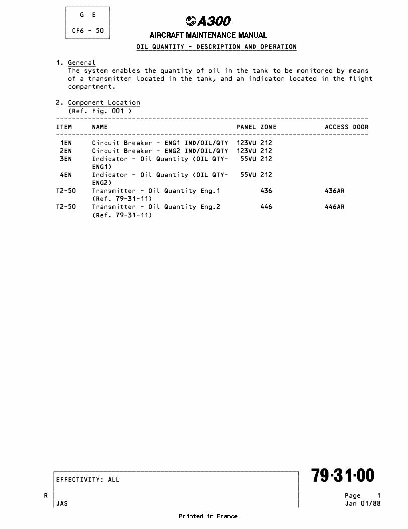
������������ � G E � � � � CF6 - 50 � ������������ OIL QUANTITY - DESCRIPTION AND OPERATION ________________________________________
1. General _______ The system enables the quantity of oil in the tank to be monitored by means of a transmitter located in the tank, and an indicator located in the flight compartment.
2. Component Location __________________ (Ref. Fig. 001 ) ------------------------------------------------------------------------------ ITEM NAME PANEL ZONE ACCESS DOOR ------------------------------------------------------------------------------ 1EN Circuit Breaker - ENG1 IND/OIL/QTY 123VU 212 2EN Circuit Breaker - ENG2 IND/OIL/QTY 123VU 212 3EN Indicator - Oil Quantity (OIL QTY- 55VU 212 ENG1) 4EN Indicator - Oil Quantity (OIL QTY- 55VU 212 ENG2) T2-50 Transmitter - Oil Quantity Eng.1 436 436AR (Ref. 79-31-11) T2-50 Transmitter - Oil Quantity Eng.2 446 446AR (Ref. 79-31-11)
�������������������������������������������������������������� �EFFECTIVITY: ALL ������������������������������������������������������������������� 79-31-00 � � � �R Page 1 � � JAS Jan 01/88

������������ � G E � � � � CF6 - 50 � ������������
Component Location - SchematicR Figure 001
�������������������������������������������������������������� �EFFECTIVITY: ALL ������������������������������������������������������������������� 79-31-00 � � � � Page 2 � � JAS Oct 30/81

������������ � G E � � � � CF6 - 50 � ������������R 3. Description (Ref. Fig. 001 ) ___________R Supplied by a 115VAC, 400 Hz power, the indicating circuits are protected by circuit breakers 1EN (2EN) located on panel 123VU. The oil tank quantity indicating circuit comprises a transmitter and an indicator.
A. Oil Quantity transmitter Situated in the oil tank, the transmitter comprises : - a potentiometer powered by 28VDC current from the indicator. - 28 reed switches. - a permanent magnet incorporated in a helium-filled hermetically sealed stainless steel float. The assembly is housed in a sealed aluminium tube.
B. Oil Quantity Indicator Located on panel 55VU in the flight compartment, the oil quantity indicator features :R - a dial graduated from 0 to 22 Quarts (0 to 22 liters) - a main pointer enabling oil consumption to be checked - an electronic assembly integral with the indicator - a BITE screw located at the rear of the indicator for testing the indi- cator. - a blue mark on the dial representing the BITE value - integral lighting
4. Operation _________ When positioned opposite one of the potentiometer reed switches, the trans- mitter permanent magnet located in the tank induces a magnetic field which is transmitted to the indicator in the form of a signal proportional to the oil level in the tank. A self-test facility (BITE) in the indicator enables the indicator to be tested for correct operation. The indicator pointer should deflect to the blue mark on the dial, interrupting the oil quantity signal from theR transmitter during the time the BITE screw is operated.
�������������������������������������������������������������� �EFFECTIVITY: ALL ������������������������������������������������������������������� 79-31-00 � � � � Page 3 � � JAS Oct 30/81

������������ � G E � � � � CF6 - 50 � ������������ OIL QUANTITY TRANSMITTER - REMOVAL/INSTALLATION _______________________________________________
NOTE : Removal/installation procedures for both LH and RH (Engine 1 or Engine 2) ____ or Engine 2) oil quantity transmitters are identical.
1. Equipment and Materials _______________________ ------------------------------------------------------------------------------- ITEM DESIGNATION ------------------------------------------------------------------------------- A. Electrical Ground Power Unit - 3-phase, 115/200V, 400Hz, 90KVA B. O-Ring C. Circuit Breaker Safety Clips D. Corrosion-Resistant Steel Lockwire 0.020 in. (0.512 mm) Dia. Referenced Procedures - 24-41-00, P. Block 301 External power - 71-13-00, P. Block 301 Cowl Doors
2. Procedure _________
A. Job Set-Up (1)Open, safety and tag the following circuit breakers : ------------------------------------------------------------------------------ PANEL SERVICE IDENT. LOCATION ------------------------------------------------------------------------------ 123VU ENGINES/START/CONTRL 2KG 301/D14 123VU ENGINES/IGNITION/SYS A 1JH 301/D16 123VU ENGINES/IGNITION/SYS B 2JH 301/D17 123VU ENG 1/REV/CONTRL 1KM 302/C 2 123VU ENG 2/REV/CONTRL 2KM 302/C15 123VU ENG 1 IND/OIL/QTY 1EN 303/B 5 123VU ENG 2 IND/OIL/QTY 2EN 303/B15
(2)Open fan cowls 436AR, Engine 1 or 446AR, Engine 2. (Ref. 71-13-00, Page Block 301). WARNING : EACH FAN COWL WEIGHS 156 POUNDS (71KG). MAKE CERTAIN SUFFICIENT _______ PERSONNEL ARE AVAILABLE TO ASSIST IN OPENING OF COWLS.
B. Removal (Ref. Fig. 401 ) WARNING : MAKE CERTAIN CIRCUIT BREAKERS ARE OPEN, SAFETIED AND TAGGED _______ BEFORE ATTEMPTING MAINTENANCE PROCEDURES. INADVERTENT ENGINE START OR THRUST REVERSER OPERATION COULD RESULT IN DEATH OR SERIOUS INJURY TO PERSONNEL. (1)Unlock and disconnect electrical connector. CAUTION : TO PREVENT DAMAGE TO ELECTRICAL CONNECTOR, DO NOT USE ANY TOOL _______ OTHER THAN PLUG PLIERS TO DISCONNECT OR CONNECT PLUG. WHEN CONNECTING PLUG, DO NOT OVERTIGHTEN. (2)Remove the four attach bolts and washers. (3)Remove oil quantity transmitter from oil tank. Discard O-ring.
�������������������������������������������������������������� �EFFECTIVITY: ALL ������������������������������������������������������������������� 79-31-11 � � � �R Page 401 � � JAS Jan 01/88

������������ � G E � � � � CF6 - 50 � ������������
Oil Quantity Transmitter Figure 401
�������������������������������������������������������������� �EFFECTIVITY: ALL ������������������������������������������������������������������� 79-31-11 � � � �R Page 402 � � JAS Jul 30/80
������������ � G E � � � � CF6 - 50 � ������������ C. Installation NOTE : Remove shipping clip prior installation of transmitter. ____ (1)Lubricate replacement O-ring with engine oil. (2)Place O-ring in position on the replacement transmitter (3)Install transmitter on oil tank with integral electrical connector facing forwards. Attach transmitter using the fourattach screws and washers. (4)Connect electrical connector and safety with 0.020 in. (0.512 mm) dia. corrosion-resistant steel lockwire.
D. Test (1)Remove safety clips and tags and close circuit breakers 1EN and 2EN. (2)Connect electrical ground power unit and ener- gize the aircraft electrical network (Ref. 24-41-00, P. Block 301). (3)Compare the tank oil level read on tank gage with reading on oil quantity indicator. (4)De-energize the aircraft electrical network and disconnect electrical ground power unit.
E. Close-Up (1)Make certain that working area is clean and clear of tools and miscellaneous items of equipment. (2)Close fan cowls (Ref. 71-13-00, P. Block 301). (3)Remove safety clips and tags and close circuit breakers 2KG, 1JH, 2JH, 1KM and 2KM.
�������������������������������������������������������������� �EFFECTIVITY: ALL ������������������������������������������������������������������� 79-31-11 � � � �R Page 403 � � JAS Jan 30/82

������������ � G E � � � � CF6 - 50 � ������������ OIL TEMPERATURE INDICATING - DESCRIPTION AND OPERATION ______________________________________________________
1. General _______ A sensor located in the scavenge oil line transmits an electrical signal to a temperature indicator located in the flight compartment.
2. Component Location __________________ (Ref. Fig. 001 ) ------------------------------------------------------------------------------ ITEM NAME PANEL ZONE ACCESS DOOR ------------------------------------------------------------------------------ 4EA Circuit Breaker - ENG2 IND/OIL/TEMP 123VU 212 9EA Circuit Breaker - ENG1 IND/OIL/TEMP 123VU 212 13EA Indicator - Oil Temperature (OIL 55VU 212 TEMP - ENG1) 14EA Indicator - Oil Temperature (OIL 55VU 212 TEMP - ENG2) B3-54 Sensor - Oil Temperature, ENG1, 435 435AL (Ref. 79-32-11) B3-54 Sensor - Oil Temperature, 445 445AL (Ref. 79-32-11) 142VD Box - Spike Suppressor 122 143VD Box - Spike Suppressor 122
�������������������������������������������������������������� �EFFECTIVITY: ALL ������������������������������������������������������������������� 79-32-00 � � � �R Page 1 � � JAS Mar 01/99

������������ � G E � � � � CF6 - 50 � ������������
Component Location - Schematic Figure 001
�������������������������������������������������������������� �EFFECTIVITY: ALL ������������������������������������������������������������������� 79-32-00 � � � �R Page 2 � � JAS Mar 01/99
������������ � G E � � � � CF6 - 50 � ������������ 3. Description ___________ (Ref. Fig. 001 ) The oil temperature indicating system is supplied with 28VDC through circuit breakers 9EA (4EA) located on panel 123VU. The oil temperature indicating system comprises: - a temperature sensor - an indicator - a spike suppressor box.
A. Oil Temperature Sensor The oil temperature sensor is located on the return line downstream of the scavenge pumps. The temperature sensor is of the resistance type composed of an insulating material, hermetically sealed and mounted in a housing with an electrical connector.
B. Oil Temperature Indicator Located on panel 55VU in the flight compartment, the oil temperature indi- cator is of the ratiometric type. The oil temperature indicator features : - a dial graduated from - 50•C to 200•C - integral lighting.
C. Spike Suppressor Box Located below 50VU in the avionics compartment, the spike suppressor box protects indicator against lightning strike effects.
4. Operation _________ When the circuit is energized, the indicator operates on the principle of a Wheatstone bridge, the sensor forming one of the arms.
�������������������������������������������������������������� �EFFECTIVITY: ALL ������������������������������������������������������������������� 79-32-00 � � � �R Page 3 � � JAS Mar 01/99
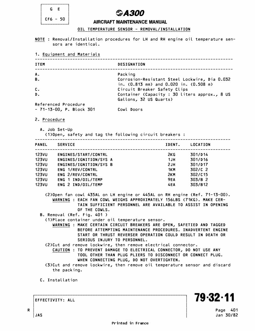
������������ � G E � � � � CF6 - 50 � ������������ OIL TEMPERATURE SENSOR - REMOVAL/INSTALLATION _____________________________________________
NOTE : Removal/Installation procedures for LH and RH engine oil temperature sen- ____ sors are identical.
1. Equipment and Materials _______________________ ------------------------------------------------------------------------------- ITEM DESIGNATION ------------------------------------------------------------------------------- A. Packing B. Corrosion-Resistant Steel Lockwire, Dia 0.032 in. (0.813 mm) and 0.020 in. (0.508 m) C. Circuit Breaker Safety Clips D. Container (Capacity : 30 liters approx., 8 US Gallons, 32 US Quarts) Referenced Procedure - 71-13-00, P. Block 301 Cowl Doors
2. Procedure _________
A. Job Set-Up (1)Open, safety and tag the following circuit breakers : ------------------------------------------------------------------------------ PANEL SERVICE IDENT. LOCATION ------------------------------------------------------------------------------ 123VU ENGINES/START/CONTRL 2KG 301/D14 123VU ENGINES/IGNITION/SYS A 1JH 301/D16 123VU ENGINES/IGNITION/SYS B 2JH 301/D17 123VU ENG 1/REV/CONTRL 1KM 302/C 2 123VU ENG 2/REV/CONTRL 2KM 302/C15 123VU ENG 1 IND/OIL/TEMP 9EA 303/B 2 123VU ENG 2 IND/OIL/TEMP 4EA 303/B12
(2)Open fan cowl 435AL on LH engine or 445AL on RH engine (Ref. 71-13-00). WARNING : EACH FAN COWL WEIGHS APPROXIMATELY 156LBS (71KG). MAKE CER- _______ TAIN SUFFICIENT PERSONNEL ARE AVAILABLE TO ASSIST IN OPENING OF THE COWLS. B. Removal (Ref. Fig. 401 ) (1)Place container under oil temperature sensor. WARNING : MAKE CERTAIN CIRCUIT BREAKERS ARE OPEN, SAFETIED AND TAGGED _______ BEFORE ATTEMPTING MAINTENANCE PROCEDURES. INADVERTENT ENGINE START OR THRUST REVERSER OPERATION COULD RESULT IN DEATH OR SERIOUS INJURY TO PERSONNEL. (2)Cut and remove lockwire, then remove electrical connector. CAUTION : TO PREVENT DAMAGE TO ELECTRICAL CONNECTOR, DO NOT USE ANY _______ TOOL OTHER THAN PLUG PLIERS TO DISCONNECT OR CONNECT PLUG. WHEN CONNECTING PLUG, DO NOT OVERTIGHTEN. (3)Cut and remove lockwire, then remove oil temperature sensor and discard the packing.
C. Installation
�������������������������������������������������������������� �EFFECTIVITY: ALL ������������������������������������������������������������������� 79-32-11 � � � �R Page 401 � � JAS Jan 30/82

������������ � G E � � � � CF6 - 50 � ������������
Oil Temperature Sensor Figure 401
�������������������������������������������������������������� �EFFECTIVITY: ALL ������������������������������������������������������������������� 79-32-11 � � � �R Page 402 � � JAS Jul 30/80

������������ � G E � � � � CF6 - 50 � ������������ (1)Lubricate new packing with engine oil. (2)Install packing, then install oil temperature sensor and safety with 0.032 in. (0.813 mm) dia. corrosion-ressitant steel lockwire. (3)Connect electrical connectorm then safety with 0.020 in. (0.508 mm) dia. corrosion-resistant steel lockwire. NOTE : Oil temperature sensor must be checked for leakage at next ____ run-up. D. Close-Up (1)Make certain taht working area is clean and clear of tools and miscel- laneous items of equipment. (2)Close fan cowls (3)Remove container (4)Remove safety clips and tags, and close circuit breakers 2KG, 1JH, 2JH, 1KM, 2KM, 9EA and 4EA.
�������������������������������������������������������������� �EFFECTIVITY: ALL ������������������������������������������������������������������� 79-32-11 � � � �R Page 403 � � JAS Jan 30/82
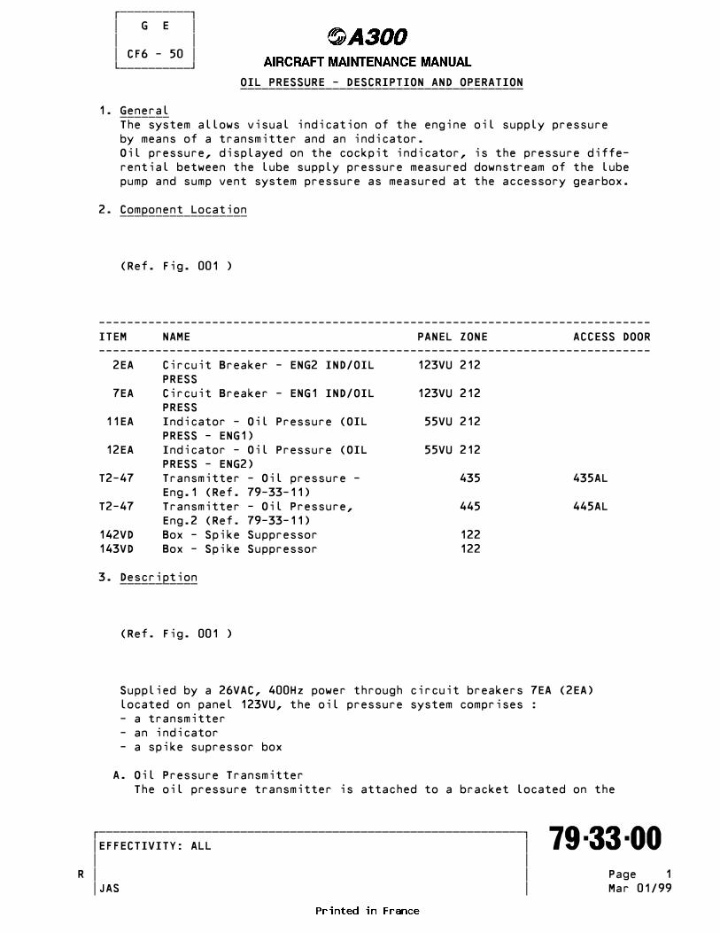
������������ � G E � � � � CF6 - 50 � ������������ OIL PRESSURE - DESCRIPTION AND OPERATION ________________________________________
1. General _______ The system allows visual indication of the engine oil supply pressure by means of a transmitter and an indicator. Oil pressure, displayed on the cockpit indicator, is the pressure diffe- rential between the lube supply pressure measured downstream of the lube pump and sump vent system pressure as measured at the accessory gearbox.
2. Component Location __________________
(Ref. Fig. 001 )
------------------------------------------------------------------------------ ITEM NAME PANEL ZONE ACCESS DOOR ------------------------------------------------------------------------------ 2EA Circuit Breaker - ENG2 IND/OIL 123VU 212 PRESS 7EA Circuit Breaker - ENG1 IND/OIL 123VU 212 PRESS 11EA Indicator - Oil Pressure (OIL 55VU 212 PRESS - ENG1) 12EA Indicator - Oil Pressure (OIL 55VU 212 PRESS - ENG2) T2-47 Transmitter - Oil pressure - 435 435AL Eng.1 (Ref. 79-33-11) T2-47 Transmitter - Oil Pressure, 445 445AL Eng.2 (Ref. 79-33-11) 142VD Box - Spike Suppressor 122 143VD Box - Spike Suppressor 122
3. Description ___________
(Ref. Fig. 001 )
Supplied by a 26VAC, 400Hz power through circuit breakers 7EA (2EA) located on panel 123VU, the oil pressure system comprises : - a transmitter - an indicator - a spike supressor box
A. Oil Pressure Transmitter The oil pressure transmitter is attached to a bracket located on the
�������������������������������������������������������������� �EFFECTIVITY: ALL ������������������������������������������������������������������� 79-33-00 � � � �R Page 1 � � JAS Mar 01/99

������������ � G E � � � � CF6 - 50 � ������������
Component Location - Schematic Figure 001
�������������������������������������������������������������� �EFFECTIVITY: ALL ������������������������������������������������������������������� 79-33-00 � � � �R Page 2 � � JAS Mar 01/99

������������ � G E � � � � CF6 - 50 � ������������ LH side of the engine beside the scavenge oil filter. The oil pressure transmitter features : - a diaphragm - a magnetic armature - two stationary coils - two moving coils - temperature stabilizing resistors. These components are enclosed in a housing provided with a pressure sensing port, a venting port and an electrical connector.
B. Oil Pressure Indicator Located in the flight compartment on panel 55VU, the oil pressure indicator features : - a dial graduated from 0 to 160 psi - an indicating pointer. - an electronic assembly integral with the indicator - a BITE screw located at the rear of the indicator for testing the indicator. - a blue mark on the dial representing the BITE value. - integral lighting
C. Spike Supressor Box Located below panel 50VU in avionics compartment, the spike suppressor box protects indicator against lightning strike effects.
R
4. Operation _________ The transmitter and the indicator form an induction bridge. Following pressure variations, the disphragm inside the transmitter moves the armature thereby resulting in inductance variation which creates a current in the moving coil of the indicator, then driving the indicator pointer. A self-test facility (BITE) in the indicator enables the indicator to be tested for correct operation. The indicator pointer must deflect to the blue mark on the dial, interrupting the oil quantity signal from the transmitter during the time the BITE screw is operated.
�������������������������������������������������������������� �EFFECTIVITY: ALL ������������������������������������������������������������������� 79-33-00 � � � � Page 3 � � JAS Mar 01/99

������������ � G E � � � � CF6 - 50 � ������������ OIL PRESSURE TRANSMITTER - REMOVAL/INSTALLATION _______________________________________________
NOTE : Removal/installation procedures for oil pressure transmitters of both ____ engine 1 and engine 2 are identical.
1. Equipment and Materials _______________________ ------------------------------------------------------------------------------- ITEM DESIGNATION ------------------------------------------------------------------------------- A. Container (Capacity : 30 Liters approx. 8 US Gallons, 32 US Quarts) B. Circuit Breaker Safety Clips C. Packings D. Corrosion-Resistant Steel Lockwire Dia 0.020 in. (0.512 mm) E. Blanking Caps Referenced Procedures - 71-13-00, P. Block 301 Cowl Doors - 71-00-00, P. Block 501 Power Plant - 12-13-79, P. Block 1 Servicing
2. Procedure _________
A. Job Set-Up (1)Open, safety and tag the following circuit breakers: ------------------------------------------------------------------------------ PANEL SERVICE IDENT. LOCATION ------------------------------------------------------------------------------ 123VU ENGINES/START/CONTRL 2KG 301/D14 123VU ENGINES/IGNITION/SYS A 1JH 301/D16 123VU ENGINES/IGNITION/SYS B 2JH 301/D17 123VU ENG 1/REV/CONTRL 1KM 302/C 2 123VU ENG 2/REV/CONTRL 2KM 302/C15 123VU ENG 2 IND/OIL/PRESS 2EA 303/B13 123VU ENG 1 IND/OIL/PRESS 7EA 303/B 3
(2)Open fan cowls 435AL on engine 1 or 445AL on engine 2. (Ref. 71-13-00, P. Block 301). WARNING : EACH FAN COWL WEIGHS 156 LBS (71KG). MAKE CERTAIN SUFFICIENT _______ PERSONNEL ARE AVAILABLE TO ASSIST IN OPENING OF THE COWLS.
B. Removal (Ref. Fig. 401 ) WARNING : MAKE CERTAIN CIRCUIT BREAKERS ARE OPEN, SAFETIED AND TAGGED _______ BEFORE ATTEMPTING MAINTENANCE PROCEDURES. INADVERTENT ENGINE START OR THRUST REVERSER OPERATION COULD RESULT IN DEATH OR SERIOUs INJURY TO PERSONNEL. (1)Place container under oil pressure transmitter. (2)Cut and remove lockwire, then disconnect electrical connector (4). CAUTION : TO PREVENT DAMAGE TO ELECTRICAL CONNECTOR DO NOT USE ANY TOOL _______ OTHER THAN PLUG PLIERS TO DISCONNECT OR CONNECT PLUG. WHEN CONNECTING PLUG, DO NOT OVERTIGHTEN.
�������������������������������������������������������������� �EFFECTIVITY: ALL ������������������������������������������������������������������� 79-33-11 � � � �R Page 401 � � JAS Jan 30/82

������������ � G E � � � � CF6 - 50 � ������������
Oil Pressure Transmitter Figure 401
�������������������������������������������������������������� �EFFECTIVITY: ALL ������������������������������������������������������������������� 79-33-11 � � � �R Page 402 � � JAS Jul 30/80

������������ � G E � � � � CF6 - 50 � ������������ (3)Disconnect and cap tubes (1) and (6) (4)Remove the four attachment bolts and washers. (5)Remove transmitter. (6)Remove and retain unions (2) and (7) mounted on transmitter. Discard packings (3) and (5).
C. Installation (1)Lubricate new packings (3) and (5) with engine oil. (2)Install packings (3) and (5); and unions (2) and (7) on replacement transmitter. Fully tighten unions. (3)Attach transmitter to bracket using the four attach bolts and washers. (4)Connect tubes (1) and (6). (5)Connect electrical connector (4) and safety with 0.020 in. (0.512 mm) dia. corrosion-resistant steel lockwire.
D. Test (1)Remove safety clips and tags, and close circuit breakers 2KG, 2EA and 7EA. (2)Dry motor engine (Ref. 71-00-00, P. Block 501). (3)Check unions (2) and (7) for leakage. (4)Check oil level in oil tank and top-up as necessary (Ref. 12-13-79, P. Block 1).
E. Close-Up (1)Make certain that working area is clean and clear of tools and miscella- neous items of equipment. (2)Close fan cowls (Ref. 71-13-00, P. Block 301). (3)Remove container. (4)Remove safety clips and tags, and close circuit breakers 1JH, 2JH, 1KM and 2KM.
�������������������������������������������������������������� �EFFECTIVITY: ALL ������������������������������������������������������������������� 79-33-11 � � � �R Page 403 � � JAS Jan 30/82
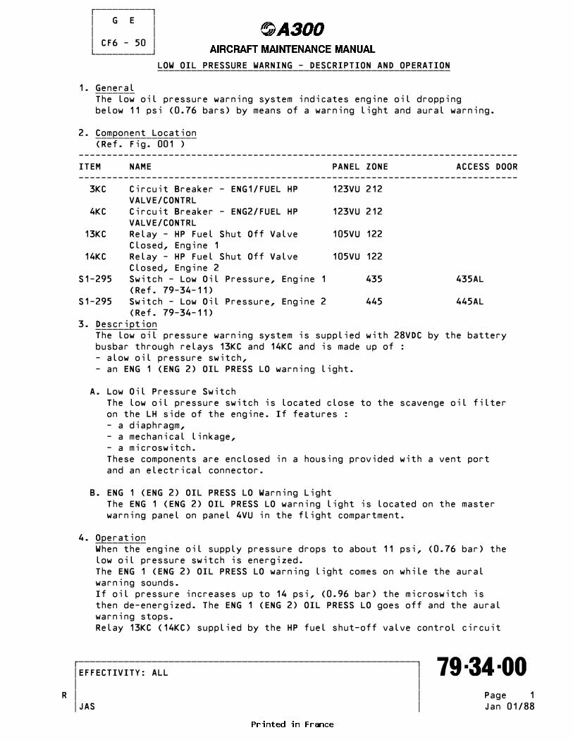
������������ � G E � � � � CF6 - 50 � ������������ LOW OIL PRESSURE WARNING - DESCRIPTION AND OPERATION ____________________________________________________
1. General _______ The low oil pressure warning system indicates engine oil dropping below 11 psi (0.76 bars) by means of a warning light and aural warning.
2. Component Location __________________ (Ref. Fig. 001 ) ------------------------------------------------------------------------------ ITEM NAME PANEL ZONE ACCESS DOOR ------------------------------------------------------------------------------ 3KC Circuit Breaker - ENG1/FUEL HP 123VU 212 VALVE/CONTRL 4KC Circuit Breaker - ENG2/FUEL HP 123VU 212 VALVE/CONTRL 13KC Relay - HP Fuel Shut Off Valve 105VU 122 Closed, Engine 1 14KC Relay - HP Fuel Shut Off Valve 105VU 122 Closed, Engine 2 S1-295 Switch - Low Oil Pressure, Engine 1 435 435AL (Ref. 79-34-11) S1-295 Switch - Low Oil Pressure, Engine 2 445 445AL (Ref. 79-34-11) 3. Description ___________ The low oil pressure warning system is supplied with 28VDC by the battery busbar through relays 13KC and 14KC and is made up of : - alow oil pressure switch, - an ENG 1 (ENG 2) OIL PRESS LO warning light.
A. Low Oil Pressure Switch The low oil pressure switch is located close to the scavenge oil filter on the LH side of the engine. If features : - a diaphragm, - a mechanical linkage, - a microswitch. These components are enclosed in a housing provided with a vent port and an electrical connector.
B. ENG 1 (ENG 2) OIL PRESS LO Warning Light The ENG 1 (ENG 2) OIL PRESS LO warning light is located on the master warning panel on panel 4VU in the flight compartment.
4. Operation _________ When the engine oil supply pressure drops to about 11 psi, (0.76 bar) the low oil pressure switch is energized. The ENG 1 (ENG 2) OIL PRESS LO warning light comes on while the aural warning sounds. If oil pressure increases up to 14 psi, (0.96 bar) the microswitch is then de-energized. The ENG 1 (ENG 2) OIL PRESS LO goes off and the aural warning stops. Relay 13KC (14KC) supplied by the HP fuel shut-off valve control circuit
�������������������������������������������������������������� �EFFECTIVITY: ALL ������������������������������������������������������������������� 79-34-00 � � � �R Page 1 � � JAS Jan 01/88

������������ � G E � � � � CF6 - 50 � ������������
Low Oil Pressure Warning - Component Location - Schematic Figure 001
�������������������������������������������������������������� �EFFECTIVITY: ALL ������������������������������������������������������������������� 79-34-00 � � � �R Page 2 � � JAS Oct 30/81

������������ � G E � � � � CF6 - 50 � ������������ makes low oil pressure warning system inoperative in order to avoid ENG 1R (ENG 2) OIL PRESS LO warning light and aural warning to be activated before engine starting.
�������������������������������������������������������������� �EFFECTIVITY: ALL ������������������������������������������������������������������� 79-34-00 � � � � Page 3 � � JAS Oct 30/81
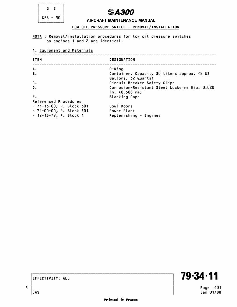
������������ � G E � � � � CF6 - 50 � ������������ LOW OIL PRESSURE SWITCH - REMOVAL/INSTALLATION ______________________________________________
NOTA : Removal/installation procedures for low oil pressure switches ____ on engines 1 and 2 are identical.
1. Equipment and Materials _______________________ ------------------------------------------------------------------------------- ITEM DESIGNATION ------------------------------------------------------------------------------- A. O-Ring B. Container. Capacity 30 liters approx. (8 US Gallons, 32 Quarts) C. Circuit Breaker Safety Clips D. Corrosion-Resistant Steel Lockwire Dia. 0.020 in. (0.508 mm) E. Blanking Caps Referenced Procedures - 71-13-00, P. Block 301 Cowl Doors - 71-00-00, P. Block 501 Power Plant - 12-13-79, P. Block 1 Replenishing - Engines
�������������������������������������������������������������� �EFFECTIVITY: ALL ������������������������������������������������������������������� 79-34-11 � � � �R Page 401 � � JAS Jan 01/88
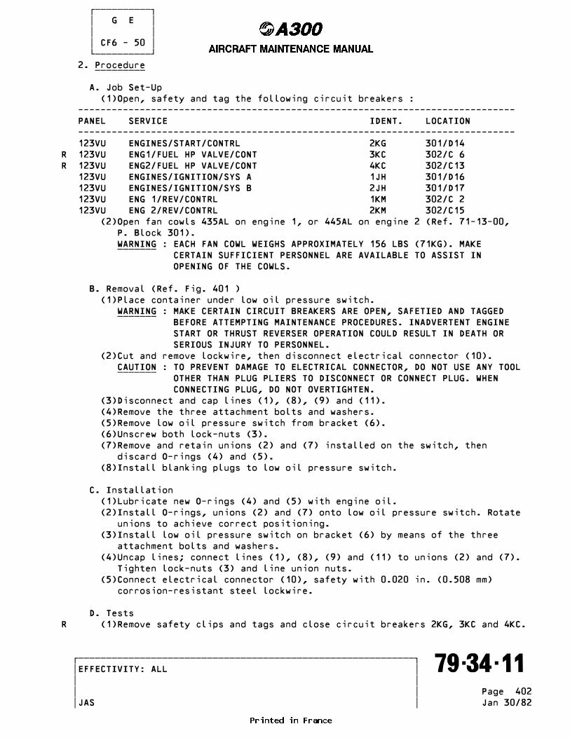
������������ � G E � � � � CF6 - 50 � ������������ 2. Procedure _________
A. Job Set-Up (1)Open, safety and tag the following circuit breakers : ------------------------------------------------------------------------------ PANEL SERVICE IDENT. LOCATION ------------------------------------------------------------------------------ 123VU ENGINES/START/CONTRL 2KG 301/D14R 123VU ENG1/FUEL HP VALVE/CONT 3KC 302/C 6R 123VU ENG2/FUEL HP VALVE/CONT 4KC 302/C13 123VU ENGINES/IGNITION/SYS A 1JH 301/D16 123VU ENGINES/IGNITION/SYS B 2JH 301/D17 123VU ENG 1/REV/CONTRL 1KM 302/C 2 123VU ENG 2/REV/CONTRL 2KM 302/C15 (2)Open fan cowls 435AL on engine 1, or 445AL on engine 2 (Ref. 71-13-00, P. Block 301). WARNING : EACH FAN COWL WEIGHS APPROXIMATELY 156 LBS (71KG). MAKE _______ CERTAIN SUFFICIENT PERSONNEL ARE AVAILABLE TO ASSIST IN OPENING OF THE COWLS.
B. Removal (Ref. Fig. 401 ) (1)Place container under low oil pressure switch. WARNING : MAKE CERTAIN CIRCUIT BREAKERS ARE OPEN, SAFETIED AND TAGGED _______ BEFORE ATTEMPTING MAINTENANCE PROCEDURES. INADVERTENT ENGINE START OR THRUST REVERSER OPERATION COULD RESULT IN DEATH OR SERIOUS INJURY TO PERSONNEL. (2)Cut and remove lockwire, then disconnect electrical connector (10). CAUTION : TO PREVENT DAMAGE TO ELECTRICAL CONNECTOR, DO NOT USE ANY TOOL _______ OTHER THAN PLUG PLIERS TO DISCONNECT OR CONNECT PLUG. WHEN CONNECTING PLUG, DO NOT OVERTIGHTEN. (3)Disconnect and cap lines (1), (8), (9) and (11). (4)Remove the three attachment bolts and washers. (5)Remove low oil pressure switch from bracket (6). (6)Unscrew both lock-nuts (3). (7)Remove and retain unions (2) and (7) installed on the switch, then discard O-rings (4) and (5). (8)Install blanking plugs to low oil pressure switch.
C. Installation (1)Lubricate new O-rings (4) and (5) with engine oil. (2)Install O-rings, unions (2) and (7) onto low oil pressure switch. Rotate unions to achieve correct positioning. (3)Install low oil pressure switch on bracket (6) by means of the three attachment bolts and washers. (4)Uncap lines; connect lines (1), (8), (9) and (11) to unions (2) and (7). Tighten lock-nuts (3) and line union nuts. (5)Connect electrical connector (10), safety with 0.020 in. (0.508 mm) corrosion-resistant steel lockwire.
D. TestsR (1)Remove safety clips and tags and close circuit breakers 2KG, 3KC and 4KC.
�������������������������������������������������������������� �EFFECTIVITY: ALL ������������������������������������������������������������������� 79-34-11 � � � � Page 402 � � JAS Jan 30/82

������������ � G E � � � � CF6 - 50 � ������������
Low Oil Pressure Switch Figure 401
�������������������������������������������������������������� �EFFECTIVITY: ALL ������������������������������������������������������������������� 79-34-11 � � � �R Page 403 � � JAS Dec 30/79

������������ � G E � � � � CF6 - 50 � ������������ (2)Dry motor engine (Ref. 71-00-00, P. Block 501). (3)Check the assembly for leakage (4)Check oil in the tank and top up if required (Ref. 12-13-79, P. Block 1).
E. Close-Up (1)Make certain that working area is clean and clear of tools and miscella- neous items of equipment. (2)Close fan cowls (Ref. 71-13-00, P. Block 301). (3)Remove container (4)Remove safety clips and tags and close circuit breakers 1JH, 2JH, 1KM and 2KM.
�������������������������������������������������������������� �EFFECTIVITY: ALL ������������������������������������������������������������������� 79-34-11 � � � �R Page 404 � � JAS Jan 30/82
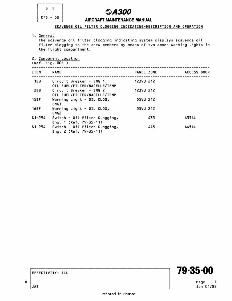
������������ � G E � � � � CF6 - 50 � ������������ SCAVENGE OIL FILTER CLOGGING INDICATING-DESCRIPTION AND OPERATION _________________________________________________________________
1. General _______ The scavenge oil filter clogging indicating system displays scavenge oil filter clogging to the crew members by means of two amber warning lights in the flight compartment.
2. Component Location __________________ (Ref. Fig. 001 ) ------------------------------------------------------------------------------ ITEM NAME PANEL ZONE ACCESS DOOR ------------------------------------------------------------------------------ 1EB Circuit Breaker - ENG 1 123VU 212 OIL FUEL/FILTER/NACELLE/TEMP 2EB Circuit Breaker - ENG 2 123VU 212 OIL FUEL/FILTER/NACELLE/TEMP 15EF Warning Light - OIL CLOG, 55VU 212 ENG1 16EF Warning Light - OIL CLOG, 55VU 212 ENG2 S1-294 Switch - Oil Filter Clogging, 435 435AL Eng. 1 (Ref. 79-35-11) S1-294 Switch - Oil Filter Clogging, 445 445AL Eng. 2 (Ref. 79-35-11)
�������������������������������������������������������������� �EFFECTIVITY: ALL ������������������������������������������������������������������� 79-35-00 � � � �R Page 1 � � JAS Jan 01/88

������������ � G E � � � � CF6 - 50 � ������������
Component Location - SchematicR Figure 001
�������������������������������������������������������������� �EFFECTIVITY: ALL ������������������������������������������������������������������� 79-35-00 � � � � Page 2 � � JAS Apr 30/80

������������ � G E � � � � CF6 - 50 � ������������ 3. Description __________ The scavenge oil filter indicating system is supplied with 28VDC through circuit breaker 1EB (2EB) located on panel 123VU. The system features : - One oil filter clogging switch S1-294 per engine - One amber ENG1 OIL CLOG (ENG2 OIL CLOG) warning light 15EF (16EF) per engine and located on panel 55VU. - One amber FILTER CLOG warning light located on master warning panel, on panel 4VU.
A. Oil Filter Clogging Switch The oil filter clogging switch is attached at the upper part of the scavenge oil filter located on the LH side of the engine. The oil filter clogging switch comprises : - A diaphragm - A mechanical linkage - A microswitch These components are enclosed in a housing which is provided with : - A pressure inlet port - A pressure outlet port - A vent port - An electrical connector
B. Warning Lights One amber ENG1 OIL CLOG (ENG2 OIL CLOG) warning light located on panel 55VU in flight compartment which can be tested manually. One amber FILTER CLOG warning light located on master warning panel, on panel 4VU.
4. Operation _________
A. Test of Warning LightsR When pressed, ENG1 OIL CLOG (ENG2 OIL CLOG) warning light comes on, toge-R ther with FILTER CLOG on masterwarning panel and the single stroke gongR gounds.When ENG1 OIL CLOG (ENG2 OIL CLOG) is released both warning lightsR go off.R B. When the differential pressure through the filter element is above 30 psid (2.1 bars), the microswitch closes, there by causing illumination of ENG1 OIL CLOG (ENG2 OIL CLOG) warning light accompanied by the single-stroke gong and also illumination of FILTER CLOG warning light.
C. If the differential pressure falls below 30 psid (2.1 bars) the micro- switch opens and the warning lights go off.
�������������������������������������������������������������� �EFFECTIVITY: ALL ������������������������������������������������������������������� 79-35-00 � � � � Page 3 � � JAS Jul 30/81

������������ � G E � � � � CF6 - 50 � ������������ OIL FILTER CLOGGING SWITCH - REMOVAL/INSTALLATION _________________________________________________
NOTE : Removal/installation procedures for oil filter clogging switches on ____ engine 1 and engine 2 are identical.
1. Equipment and Materials _______________________ ------------------------------------------------------------------------------- ITEM DESIGNATION ------------------------------------------------------------------------------- A. O-Rings B. Container - Capacity : 30 liters approx. (8 US Gallons; 32 US Quarts) C. Circuit Breaker Safety Clips D. Corrosion-Resistant Steel Lockwire, Dia. 0.020 in. (0.508 mm) E. Blanking Plugs/Caps Referenced Procedures - 71-13-00, P. Block 301 Cowl Doors - 71-00-00, P. Block 501 Power Plant - 12-13-79, P. Block 1 Replenishing - Engines
2. Procedure _________
A. Job Set-Up (1)Open, safety and tag the following circuit breakers : ------------------------------------------------------------------------------ PANEL SERVICE IDENT. LOCATION ------------------------------------------------------------------------------ 123VU ENGINES/START/CONTRL 2KG 301/D14 123VU ENGINE/IGNITION/SYS A 1JH 301/D16 123VU ENGINE/IGNITION/SYS B 2JH 301/D17 123VU ENG 1/REV/CONTRL 1KM 302/C 2 123VU ENG 2/REV/CONTRL 2KM 302/C15 123VU ENG1/OIL FUEL/FILTER/NACELLE/TEMP IND 1EB 303/B 1 123VU ENG2/OIL FUEL/FILTER/NACELLE/TEMP IND 2EB 303/B11
(2)Open fan cowls 435AL on engine 1, or 445AL on engine 2 (Ref. 71-13-00, P. Block 301). WARNING : EACH FAN COWL WEIGHS 156LBS (71KG). MAKE CERTAIN SUFFICIENT _______ PERSONNEL ARE AVAILABLE TO ASSIST IN OPENING OF THE COWLS.
B. Removal (Ref. Fig. 401 ) (1)Place container under oil filter clogging switch. WARNING : MAKE CERTAIN CIRCUIT BREAKERS ARE OPEN, SAFETIED AND TAGGED _______ BEFORE ATTEMPTING MAINTENANCE PROCEDURES. INADVERTENT ENGINE START OR THRUST REVERSER OPERATION COULD RESULT IN DEATH OR SERIOUS INJURY TO PERSONNEL. (2)Cut and remove lockwire, then disconnect electrical connector (7). CAUTION : TO PREVENT DAMAGE TO ELECTRICAL CONNECTOR, DO NOT USE ANY TOOL _______ OTHER THAN PLUG PLIERS TO DISCONNECT OR CONNECT PLUG. WHEN CONNECTING PLUG, DO NOT OVERTIGHTEN.
�������������������������������������������������������������� �EFFECTIVITY: ALL ������������������������������������������������������������������� 79-35-11 � � � �R Page 401 � � JAS Jan 30/82

������������ � G E � � � � CF6 - 50 � ������������
Scavenge Oil Filter Clogging Switch Figure 401
�������������������������������������������������������������� �EFFECTIVITY: ALL ������������������������������������������������������������������� 79-35-11 � � � �R Page 402 � � JAS Dec 30/79

������������ � G E � � � � CF6 - 50 � ������������ (3)Disconnect and cap lines (1) and (6). (4)Remove the three attachment screws and washers. (5)Remove oil filter clogging switch from bracket (8). (6)Remove and retain unions (2) and (5) from the switch, then discard O-rings (3) and (4). (7)Cap switch ports.
C. Installation (1)Lubricate new O-rings (3) and (4) with engine oil. (2)Install unions (2) and (5), with the O-rings, on the replacement switch. (3)Attach oil filter clogging switch to bracket (8) using the three attachment screws and washers. (4)Uncap and connect lines (1) and (6) to unions. (5)Connect electrical connector (7) and safety with 0.020 in. (0.508 mm) Dia. corrosion-resistant steel lockwire.
D. Test (1)Connect compressed air source to oil pressure inlet union of pressure switch. (2)Remove safety clips and tags and close circuit breaker 2KG. - 1EB, 2EB (3)Connect electrical ground power unit and energize the aircraft electrical network (Ref. 24-41-00, P. Block 301). (4)Supply compressed air at a pressure between 30 and 32.5 psig (2.06 and 2.24 bar). (5)Check that ENG 1 OIL CLOG (ENG 2 OIL CLOG) warning light on panel 55VU and FILTER CLOG warning light on master warning panel are on and accom- panied by single-stroke gong. (6)Slowly reduce air pressure to 27.5 psig (1.89 bar) and stabilize it at this pressure. (7)On panel 55VU, ENG 1 OIL CLOG (ENG 2 OIL CLOG) warning light and FILTER CLOG warning light on master warning panel should go off. (8)Disconnect compressed air source. (9)Connect line to filter. (10)Dry motor engine (Ref. 71-00-00, P. Block 501). (11)Check unions for leakage. (12)Check the oil level in the oil tank and top-up as necessary (Ref. 12-13-79, P. Block 1).
E. Close-Up (1)Make certain that working area is clean and clear of tools and miscella- neous items of equipment. (2)Close fan cowls (Ref. 71-13-00, P. Block 301). (3)Remove container (4)Remove safety clips and tags and close the circuit breakers 1JH, 2JH, 1KM and 2KM.
�������������������������������������������������������������� �EFFECTIVITY: ALL ������������������������������������������������������������������� 79-35-11 � � � �R Page 403 � � JAS Jan 30/82